Articles
Production of Titanium Films via Segregation of Ce-Ti Alloy Coexisting with LiF-based Molten Salts

2024 Volume 92 Issue 4 Pages 043025

Details
2024 Volume 92 Issue 4 Pages 043025
Titanium (Ti) is widely desired in various industries because of its excellent properties. However, use of Ti is limited owing to the high costs associated with the extraction, melting, and rolling processes. In this study, we present a novel Ti film production process that does not require melting of Ti. To improve the practicality of the process, Ti films were formed through the reaction of Li2TiF6 with Ce and subsequent segregation in a Mo crucible. A Ti film with a thickness of 10 µm was obtained when 0.7 g of Li2TiF6 was added to 1.3 g of LiF molten salt on 8 g of liquid Ce in a Mo crucible, which reacted at 1000 °C for 9 h to form a Ce-Ti alloy. The alloy was maintained at 900 °C for 9 h to promote segregation. The thickness of the Ti film increased up to 90 µm when the segregation time was increased to 18 h, whereas an increase in the reaction time did not significantly affect the thickness of the Ti film. However, a decrease in the reaction time to 4.5 h inhibited the formation of the Ti film. When the Ce-Ti alloy with excess Ti at the bottom of the Mo crucible was segregated, a Ti film did not form on the Ce/molten salt interface. Furthermore, an increase in the amount of Li2TiF6 added to the molten LiF inhibited the formation of the Ti films as the Ce surface was covered with precipitates of CeOxFy. The mechanism of the formation of the Ti film via the segregation of the Ce-Ti alloy coexisting with LiF-based molten salts was explored based on these results.
Titanium (Ti) exhibits a high melting point and specific strength, along with excellent corrosion resistance. Consequently, it is widely implemented in various fields such as engine blades in the aircraft industry and heat exchangers in chemical plants. The demand for Ti is expected to further increase because of its potential for application in various fields such as separators for fuel cells in the automotive sector and roofing materials in the civil engineering sector.1–4 Ti in the form of sheets and films is employed in these sectors. Although Ti deposits are abundant, Ti is expensive due to the high cost of extraction, melting, and rolling. Therefore, producing sufficient amounts of Ti with affordable cost to satisfy the growing demand in various fields is challenging.
In this study, we focused on Ti in the form of sheets and films, which are conventionally produced by fabricating Ti ingots or slabs using Ti sponge produced by the Kroll process. This process is described as follows.5 Ti feeds such as natural rutile, synthetic rutile, and upgraded ilmenite react with Cl2 in the presence of coke and are subsequently distilled into highly pure TiCl4, which is then reduced using Mg. Subsequently, Mg and MgCl2 are separated via vacuum distillation to obtain Ti sponge. The Ti sponge is then melted through vacuum arc melting or electron beam melting to obtain ingots or slabs that are rolled into sheets or films.6 Approximately two-thirds of the total cost of producing a Ti sheet with a thickness of 2.54 cm is attributed to the melting and rolling processes.7 Therefore, the production costs of Ti sheets and films can be effectively reduced by reducing the costs of the melting and rolling processes. Kishimoto et al. reported a method of producing Ti films by exfoliating electrodeposited Ti onto Mo or glassy carbon.8 Peter et al. reported a process of rolling sintered Ti hydrides on Ti films.9 Fujii and Okui reported a similar method, in which a Ti sponge compressed into a briquette was rolled into a sheet form.10 These processes do not require melting of Ti, thereby reducing the costs associated with melting. Recently, we demonstrated that Ti thin films were formed at the interface between LiF-TiFx molten salts and liquid Ce.11 Therefore, a novel production process for Ti films can be developed by controlling this phenomenon.
In this study, we analyzed the principle of the formation of a Ti film at the interface between liquid Ce and molten salts from a thermodynamic perspective. We then presented the experimental results of the reaction of Li2TiF6 with Ce and the subsequent segregation of Ce-Ti alloys. We also elucidated the mechanism for the formation of the Ti film at the liquid Ce/molten salt interface.
Figure 1 shows the phase diagram of the Ce-Ti binary system.12 This is a biased eutectic system that does not form intermetallic compounds between Ce and Ti. Ti dissolves in liquid Ce and its solubility increases with temperature. Consequently, Ti precipitates when a Ce-Ti liquid alloy containing a saturated amount of Ti at a given temperature is cooled. The amount of precipitated Ti can be determined from the solubility difference determined from the difference in temperature. Here, the melting points of Ce and Ti are Tm(Ce) = 798 °C and Tm(Ti) = 1668 °C, respectively. Therefore, the energy consumption associated with melting Ce should be lower than that associated with melting Ti. The densities of Ce and Ti at 900 °C are ρCe(900) = 6.66 g cm−3 and ρTi(900) = 4.48 g cm−3, respectively.13,14 When Ce-Ti alloys are cooled from high temperatures to 900 °C, Ti precipitates from Ce-Ti alloys via segregation. The Ti floats on the surface of the liquid Ce. Because the liquid Ce surface is smooth, the precipitated Ti also becomes smooth, similar to a film. James reported that a flat interface can be observed when the water solidifies.15 Glass sheets are typically produced through the floating process, which involves pouring molten glass on liquid tin.16 In the solidification of aluminum alloys, when the temperature gradient from the solid–liquid interface to the liquid phase is positive and no compositional supercooling is observed, the solid phase grows with a flat interface.17 Their reports support the formation of a smooth Ti film on the liquid Ce. Consequently, the Ti film can be obtained by segregating the Ce-Ti alloy instead of melting the Ti.
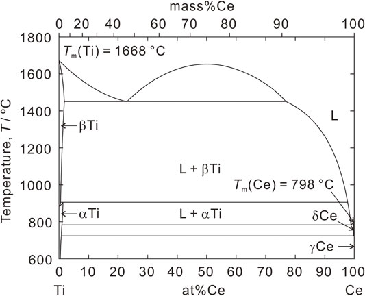
Phase diagram of the Ti-Ce binary system.12
Figure 2 depicts the variation in the standard Gibbs energy change for the fluorination of selected metals with temperature, which was evaluated using thermodynamic data from the literature.18 Ce serves as a reducing agent for Ti fluoride. When Ti fluoride is reduced with a large amount of Ce at high temperatures, the following reaction produces liquid Ce-Ti alloys (Ce1−xTix) and CeF3:
| \begin{equation} x\text{TiF}_{3} + \text{Ce} \to \text{Ce$_{1 - x}$Ti$_{x}$} + x\text{CeF}_{3}. \end{equation} | (1) |
CeF3 is the by-product that must be separated from the Ce-Ti alloys. However, it has high melting and boiling points; Tm(CeF3) = 1430 °C and Tb(CeF3) = 2327 °C. Consequently, employing vacuum distillation or melting to separate the CeF3 from the Ce-Ti alloys is challenging. However, the addition of a molten salt as a flux effectively dissolves CeF3 for separation. The flux must remain stable in the presence of Ce. Figure 2 indicates that LiF is stable in the presence of Ce. When LiF is introduced into reaction (1), a LiF-CeF3 molten salt is formed. The density of the LiF-CeF3 molten salt, which can be determined from the densities of LiF and CeF3, lies within the range of 1.79–2.74 g cm−3 at 900 °C, which is lighter than that of Ce.19 Here, the lower limit of density corresponds to the density of pure LiF at 900 °C.20 The upper limit was determined as the density of the 71.6 mol%LiF-28.4 mol%CeF3 molten salt, which is the saturated composition of CeF3 at 900 °C in the LiF-CeF3 system. Therefore, the LiF-CeF3 molten salt floats on the Ce-Ti alloy, allowing the two phases to be easily separated.

Standard Gibbs energy change of the fluorination reactions for the selected metals per mol of fluorine at each temperature.18
Based on the thermodynamic background explained above, the Ti film is formed through the reaction mechanism depicted in Fig. 3. The Ti feeds are dissolved in the molten salt and reduced to a Ce-Ti alloy by Ce. Subsequently, the Ce-Ti alloy is cooled to precipitate Ti at the interface between Ce and the molten salt into film form via segregation. Sato and Sekimoto demonstrated this principle and observed that slow cooling after the reaction of the LiF-TiF3 molten salt with Ce produced a Ti film with a thickness of 40 µm at the interface between the molten salt and Ce.11 This phenomenon can potentially be used to develop a unique process to obtain films of metals with high melting points such as Ti, without the need for melting itself and rolling. As the next steps in realizing this process, enhancing the reproducibility of Ti film formation, controlling the thickness of Ti films, developing a technique for recoverying Ti films, and evaluating the properties of Ti films are crucial. The thickness of the Ti film could be determined based on the difference between the concentration of Ti in the Ce-Ti alloy formed at the reaction temperature and the solubility of Ti in Ce at the segregation temperature. Thus, the thickness of the Ti films could be increased by controlling these parameters. Therefore, analyzing the reaction and segregation using Ce, Li2TiF6, or Ti is crucial.

Reaction flow for the formation of Ti films via segregation of Ce-Ti alloy.
Metallic Ce, LiF, Li2TiF6, and metallic Ti were used as the feed materials. Ce ingots with a diameter of 12.7 mm (99.9 %, The Nilaco Co.) were cut to a length of approximately 10 mm in the air using an oil coolant (Hyprez, OS Lubricant, Engis Japan Co.) to prepare approximately 8 g of Ce, which was polished to remove surface oxides in an Ar-filled glove box before usage. LiF pellet was prepared using a mold with a diameter of 10 mm (DT3025A-1020, NPa System Co., Ltd.). Briefly, 1.3 g of LiF (GR, Kanto Chemical Co., Inc.) was weighed and pressed onto the disk with the mold at a uniaxial load of approximately 60 MPa. The disk was then divided into small pieces. Li2TiF6 was prepared using a wet process from Li2CO3 (GR, Kanto Chemical Co., Inc.) and 60 % H2TiF6 solution (99.9 % trace metal basis, Sigma-Aldrich).11,21 Li2TiF6 was divided into small pieces in the same manner as that of LiF. A Ti wire with a diameter of 2 mm and length of 5 mm (99.9 %, KOJUNDO CHEMICAL LABORATORY Co., Ltd.) was used as the metallic Ti.
3.2 Procedure for the formation of Ce-Ti alloy and its segregationA series of experiments were conducted on the reaction of Li2TiF6 dissolved in LiF molten salt with liquid Ce and the segregation of the Ce-Ti alloy in an Ar-filled glove box. The partial pressures of water vapor and oxygen in the box were maintained below 1 ppm. A Mo crucible with a diameter of 15 mm and height of 15 mm (99.95 %, The Nilaco Co.) was coated with BN to decrease the wettability of Ce on Mo. Here, the BN coating on the Mo crucible was prepared using the following procedure. A Mo crucible was dipped in a BN slurry (C-20AL, MARUKA Co., Ltd.) and then pulled up to drain off the excess slurry. Subsequently, the Mo crucible was dried at 100 °C for more than 0.5 h. Metallic Ce was placed in the Mo crucible and then inserted into a graphite crucible within a SUS304 crucible. The SUS304 crucible was then placed in an electric furnace with a quartz reaction tube. According to preliminary experiments, the temperature distribution in the sample was limited to 3 °C, and the temperature near the interface between the molten salt and Ce was the highest. The sample was heated to 900 °C to melt Ce, and 1.3 g of LiF was then placed on its surface to form the LiF molten salt. Subsequently, a specific amount of Li2TiF6 (w(Li2TiF6)) was added to the molten LiF to form a LiF-TiF4 molten salt to simplify the film fabrication process. The sample was then heated to a reaction temperature (TR = 1000 °C) for a specified duration to promote the reaction between TiF4 in the molten salt and Ce. Following the reaction, the furnace was cooled to a segregation temperature (TS = 900 °C) and maintained for a specified duration to promote the segregation of Ti. Hereafter, the time required for the reaction and segregation are referred to as “reaction time (tR)” and “segregation time (tS),” respectively. After segregation, the samples were cooled to room temperature for recovery. Table 1 summarizes the experimental conditions. Exp. A–G were conducted to analyze the effects of the reaction and segregation time on the characteristics of the Ti films formed at the molten salt/Ce interface. Exp. H, Ha1 and Ha2 were conducted with the understanding that the Ti film thickness would increase as the amount of Li2TiF6 added to the molten LiF increased. In Exp. I, metallic Ti was placed into the Mo crucible along with Ce to form an alloy between Ce and Ti, and Li2TiF6 was not added to the molten LiF salt. This condition was examined to analyze the characteristics of the Ti films via the segregation of the Ce-Ti alloy. The molar ratio of Ce to Ti was approximately 90/10, which was larger than the solubility of Ti in Ce at 1000 °C, indicating that segregation occurred under Ti supersaturation conditions.
| Exp. No. |
Reaction time, tR/h |
Segregation time, tS/h |
Reaction temperature, TR/°C |
Segregation temperature, TS/°C |
Weight of feed, w(i)/g |
|
|---|---|---|---|---|---|---|
| Li2TiF6 | Ti | |||||
| A | 18 | 18 | 1000 | 900 | 0.7 | |
| B | 9 | 4.5 | 1000 | 900 | 0.7 | |
| C | 9 | 9 | 1000 | 900 | 0.7 | |
| D | 9 | 12 | 1000 | 900 | 0.7 | |
| E | 9 | 18 | 1000 | 900 | 0.7 | |
| F | 4.5 | 4.5 | 1000 | 900 | 0.7 | |
| G | 4.5 | 9 | 1000 | 900 | 0.7 | |
| H | 9 | 9 | 1000 | 900 | 2.1 | |
| Ha1 | 9 | 9 | 1000 | 900 | 1.4 | |
| Ha2 | 9 | 9 | 1000 | 900 | 2.8 | |
| I | 9 | 9 | 1000 | 900 | 0.2 | |
All the samples were embedded in an epoxy resin (HERZOG EPO, low-viscosity type, HERZOG JAPAN Co., Ltd.) along with the corresponding Mo crucible. The samples were cut to expose the interface between the molten salt and Ce, polished with emery paper, and buffed with diamond slurry in an oil lubricant. After washing the samples with ethanol, carbon was deposited on the samples intended for SEM-EDS observation to verify the formation of the Ti film at the interface between the LiF-based molten salt and Ce, and to evaluate the thickness of the Ti film.
Figure 4 presents a backscattered electron composition (BSE-C) image of the cross section of the sample prepared at tR = 9 h and tS = 9 h (Exp. C), along with the elemental distribution maps for Ti, Ce, O, and F corresponding to the BSE-C area. The presence of F and Ce was confirmed in the speckled eutectic structure in the upper region of the BSE-C image, indicating that the white areas are CeF3 and the black areas are LiF in the speckled structure. Thus, this region corresponds to the LiF-CeF3 molten salt. The Ti distribution map indicates that the gray area in the middle of the BSE-C image is metallic Ti. EDS analysis results indicate that Ce was not present in the metallic Ti phase. Ce, O, and a small amount of Ti can be observed in the lower region of the BSE-C image. This region corresponds to the liquid Ce phase. During the cutting or polishing of the sample, O may be introduced into the Ce phase because Ce is readily oxidized in such an atmosphere. The Ti distributed in the Ce phase was probably precipitated from the Ce-Ti alloy after the end of the segregation step. Figure 4 demonstrates that a Ti film with a thickness of approximately 10 µm exists at the interface between the LiF-CeF3 molten salt and Ce. Therefore, the Ti films were successfully obtained from Li2TiF6, whereas LiF-TiF3 molten salt was used in a previous study.11 As shown in the elemental distribution map for Ti in Fig. 4, no Ti fluorides were presented in the molten salt phase, indicating that nearly all of the TiF4 in the molten salt was reduced by Ce. The Ti remains in the Ce phase, as shown in Fig. 4, and thicker Ti films can potentially be obtained by optimizing tR and tS.
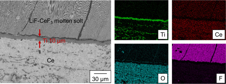
BSE-C image of the sample obtained under condition C (tR = 9 h, tS = 9 h) and the element distribution images of the corresponding areas for Ti, Ce, O, and F.
Figure 5 depicts the BSE-Cs for the interface between Ce and the molten salt for the samples prepared at various tR and tS values (Exp. A–G). Figure 5C depicts the same BSE-C as that in Fig. 4. In all the samples, the LiF-CeF3 molten salt phase was observed in the upper area, and the Ce phase was observed in the lower area. When comparing the samples at tR = 9 h (Exp. B, C, D, and E), thicker Ti films were observed at the interface between Ce and the molten salt, except for the sample with tS = 4.5 h. The thickness of the film was approximately 50 µm in the sample of tS = 12 h and approximately 90 µm in the sample of tS = 18 h, while no Ti film was observed in the sample of tS = 4.5 h. According to the EDS analysis, a significant amount of Ce was present in the Ti films. Figure 6 illustrates the variation of the thickness of Ti films (d) to tS, where tR = 9 h. The thickness of the Ti films increased with increasing tS. The maximum thickness of the Ti film was evaluated from the phase diagram shown in Fig. 1. Li2TiF6 was dissolved in the LiF molten salt to form TiF4, which was reduced by Ce to TiF3.
| \begin{equation} 3\text{TiF}_{4} + \text{Ce} \to 3\text{TiF}_{3} + \text{CeF}_{3} \end{equation} | (2) |
TiF3 is further reduced to a Ce-Ti alloy through the reaction presented in Eq. (1). Assuming that all the Li2TiF6 added is reduced, 0.74 g of Ce is consumed and 0.2 g of Ti is formed via reactions (1) and (2). This Ti (0.2 g) dissolves in the remaining Ce (7.26 g), forming a Ce-7 mol%Ti alloy (Ce0.93Ti0.07). However, the solubility of Ti in liquid Ce at 1000 °C is approximately 4 mol%. Consequently, Ce-4 mol%Ti (Ce0.96Ti0.04) formed, and the excess Ti was precipitated on the Ce-Ti alloy surface. When the Ce-Ti alloy was cooled to 900 °C at which the solubility of Ti in Ce is 2 mol%, the amount of precipitated Ti was equivalent to 2 mol%. When the diameter of the Mo crucible was 15 mm, the maximum thickness of the Ti film was 247 µm. The yield of Ti produced as a film reached up to 36 % when tS = 18 h. Ti that was not precipitated on the Ce surface in film form may either be found at the grain boundaries of Ce or evaporated as TiF4 before dissolving into the LiF molten salt. Extrapolating the plot in Fig. 6 to d = 0 mm indicates that tS = 4.5 h was insufficient for forming a Ti film. At tR = 4.5 h (Exp. F and G), no Ti film was observed, regardless of the tS value. The reasons for these results are discussed in detail in Section 5. Comparing the samples of tS = 18 h (A and E), the thickness of the Ti films formed under the condition of tR = 18 h was approximately 90 µm, which was nearly identical to that of tR = 9 h. Because Ti fluorides in the molten salt phase were depleted within tR = 9 h, Ti films did not grow in the reaction time, despite tR being prolonged. Therefore, prolonging the reaction time does not significantly affect the increase in film thickness.
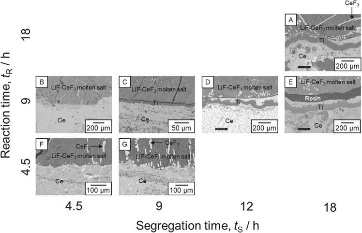
BSE-C images of the samples obtained under different tR and tS conditions. Table 1 presents the details of the conditions (Exp. A–G). The area including the Ce/molten salt interface was observed.
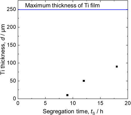
Relationship between segregation time and thickness of Ti formed at the Ce/molten salt interface, with tR = 9 h.
Ti film failed to form when the amount of Li2TiF6 added to the molten LiF was increased to obtain a thicker Ti film. Figure 7 presents a BSE-C image of the Ce/molten salt interface of the sample prepared under the condition of w(Li2TiF6) = 2.1 g (Exp. H). The upper region contains the LiF-CeF3 molten salt, and the lower region contains Ce. Under this condition, the formation of CeOxFy, which may be a solid solution of CeOF and CeF3, was observed at the interface between the molten salt and Ce. Oxide ions may have been introduced into the molten LiF from trace oxides on the Ce ingot. EDS analysis results indicate that Ti is not observed in the Ce phase. The formation of CeOxFy was also confirmed under the conditions of w(Li2TiF6) = 1.4 g and 2.8 g (Exp. Ha1 and Ha2), whereas CeOxFy was not formed under the conditions of w(Li2TiF6) = 0.7 g (Exp. C). Therefore, the addition of excess amount of Li2TiF6 promoted the precipitation of CeOxFy on the Ce surface, thereby inhibiting the formation of Ce-Ti alloys. Consequently, the formation of Ti films did not occur.
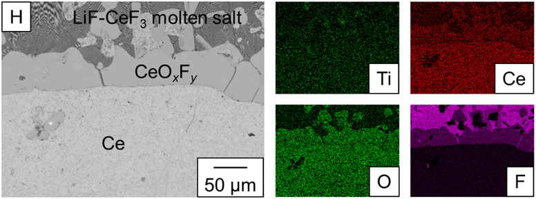
BSE-C image of the interface between molten salt and Ce in Exp. H.
The Ti films were formed through the segregation of Ti from the Ce-Ti alloy produced through the reaction between TiF4 in the molten salt and Ce, as explained in Section 4.1. However, they were not formed via the segregation of Ti from the Ce-Ti alloy prepared by alloying Ce and Ti (Exp. I). Because the soluble amount of Ti in 8 g of Ce was 0.1 g at 1000 °C according to Fig. 1, a part of the Ti did not dissolve in the Ce-Ti alloy. Excess Ti wires were observed at the bottom of the Mo crucible. Figure 8(a) shows a BSE-C image of the interface between the Mo crucible and Ce. The Ce and Mo phases are located on the left and right sides, respectively. The BN coatings on Mo crucible was not observed, indicating that BN likely exfoliated to be dispersed in the liquid phases or dissolved in Ce. Ti film with a thickness of approximately 5–10 µm can be observed between the Mo and Ce. The amount of Ti that precipitated on the Ce surface was extremely small. The formation of Ti at the Ce/Mo interface was also observed at tR = 4.5 h (Exp. B and F), as shown in Fig. 8(b). This indicates that Mo served as a Ti nucleation site when the amount of Ti on the Ce surface was negligible. Therefore, the use of the Mo crucible may have suppressed the formation and growth of the Ti films at the Ce/molten salt interface.
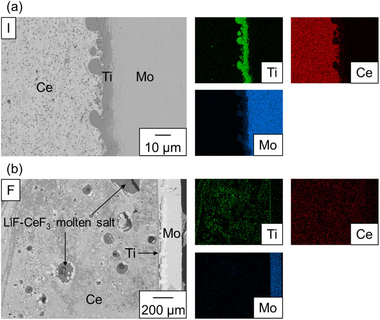
BSE-C image of the interface between Ce and the Mo crucible. (a) Exp. I. (b) Exp. F.
Based on the results described above, we discuss the mechanism of the formation of Ti films through the reaction of the LiF-TiF4 molten salt with Ce and the subsequent segregation of Ti from the Ce-Ti alloy. The Ti film was not observed on the sample where the Ce surface was covered with CeOxFy. Under the conditions where the reaction time was less than 9 h or where the Ce-Ti alloy was prepared using metallic Ce and Ti at 1000 °C, Ti films did not form, and most of the Ti precipitated at the interface between the Mo crucible and Ce. Based on the conditions under which Ti films were successfully formed, it was essential to segregate the Ce-Ti alloys saturated with Ti, which were produced through the reaction of TiF4 in the molten salt and Ce with a sufficient reaction time. Even when the reaction time was increased, the thickness of the Ti films did not change significantly when the segregation time remained unchanged. The possible reaction mechanisms were proposed based on these factors, as shown in Fig. 9.

Mechanism for the formation of Ti films under: (a) excess concentration of TiF4 in LiF-TiF4 molten salt; (b) appropriate condition; and (c) no Ti precipitates on liquid Ce surface.
Figure 9(a) illustrates a case where CeOxFy is formed to cover the surface of Ce. The dissolution of Li2TiF6 in the molten LiF forms LiF-TiF4 molten salt. TiF4 in this molten salt is reduced to Ti to form CeF3. If all of the TiF4 is reduced, the concentration of CeF3 reaches 8.4 mol%. As shown in Fig. 5, coarse CeF3 grains can be observed in the LiF-CeF3 molten salt near the Ce surface under various conditions. This microstructure is typically observed when undissolved CeF3 particles are present or the concentration of CeF3 is high relative to the eutectic composition (18 mol%). Consequently, this suggest that the rate of CeF3 formation was fast relative to its dissolution and diffusion rate in the molten salt, resulting in an increased concentration of CeF3 in the molten salt near the Ce surface. In addition, the molten LiF contained a considerable amount of oxide ions (O2−) owing to the dissolution of trace oxides on the Ce ingot. When the concentration of TiF4 in LiF-TiF4 molten salt was excessively high, the CeF3 concentration near the Ce surface surpassed the value determined by the solubility of CeOxFy, which was precipitated through the following reaction:
| \begin{equation} \text{Ce}^{3 + } + x\text{O}^{2 - } + y\text{F}^{ - } \to \text{CeO$_{x}$F$_{y}$} \end{equation} | (3) |
The CeOxFy covered the Ce surface. This prevented any contact between the Ce and TiF4; thus, a Ce-Ti alloy was not formed. Similar results were obtained when LiF-CeF3-TiF3 molten salt was reacted with Ce in our previous study. Therefore, an excess concentration of CeF3 in the molten salt near the Ce inhibits the formation of Ti films.
Figure 9(b) illustrates the reaction mechanism for obtaining highly reproducible Ti films. The TiF4 in the LiF-TiF4 molten salt is reduced by Ce to form Ce-Ti alloys. The by-product, CeF3, can dissolve in the molten salt. Because the concentration of TiF4 was appropriate, the concentration of CeF3 near the Ce did not exceed the value determined by the solubility of CeOxFy. When the amount of Ti formed through the reduction by Ce exceeded the solubility of Ti in liquid Ce at the reaction temperature, undissolved Ti precipitated in the film form as a seed at the interface between the molten salt and Ce. Under these conditions, the Ti films provide nucleation sites during segregation rather than the Mo crucible. Therefore, the Ti films grew thicker with an increase in the segregation time. This mechanism effectively explains the reason for obtaining almost the same thickness of the Ti film at the same segregation time when the reaction time was varied.
Figure 9(c) shows the challenge faced in forming Ti films when the segregation of Ce-Ti alloys proceeds without excess Ti precipitates on the liquid Ce surface. This case was observed either when the reaction time was insufficient, or when the Ce-Ti alloys were prepared from metallic Ce and Ti. When the reaction time for the reduction of TiF4 in the molten salt by Ce was insufficient, Ti films, which provide nucleation sites, were not formed on the Ce surface (Exp. B and F). When the Ce-Ti alloy was prepared by alloying metallic Ce and Ti, undissolved Ti accumulated at the bottom of the Mo Crucible, resulting the absence of Ti precipitates on the liquid Ce surface (Exp. I). Under these conditions, the amount of Ti precipitating at the interface between Ce and the molten salt was negligible, and a large portion of the Ti was precipitated at the interface between Mo and Ce via the segregation of Ce-Ti alloys. Consequently, the formation and growth of Ti films at the interface between the molten salt and liquid Ce were inhibited, while those at the Ce/Mo interface were promoted, as shown in Fig. 9(c).
This explanation suggests that to produce a thick Ti film with high reproducibility, it is essential to provide an appropriate amount of Li2TiF6 and reaction time to produce a Ce-Ti alloy with a high Ti concentration and a Ti film as a nucleation site on its surface.
This study aimed to develop a novel Ti film production process that does not require the melting of Ti. The novelty of this process is the segregation of the Ce-Ti alloy coexisting with the molten salt. To improve the practicality of the process, we analyzed the formation of Ti films through the reaction of Li2TiF6 with Ce and subsequent segregation in a Mo crucible. We also evaluated the effects of reaction and segregation times on the formation and growth of Ti films at the Ce/molten salt interface.
A thick Ti film was obtained with high reproducibility when 0.7 g of Li2TiF6 was added to 1.3 g of LiF molten salt on 8 g of liquid Ce to react at 1000 °C for 9 h to form a Ce-Ti alloy, which was then maintained at 900 °C for 9 h. The thickness of the Ti film increased up to 90 µm when the segregation time was increased to 18 h, whereas increasing the reaction time did not significantly affect the thickness of the Ti film. However, decreasing the reaction time to 4.5 h inhibited the formation of the Ti film. When the Ce-Ti alloy with a low Ti concentration was segregated, a Ti film did not form on the Ce surface. These results can be explained by the reaction model, where the Mo crucible becomes a nucleation site for Ti. Furthermore, an increase in the amount of Li2TiF6 added to the molten LiF inhibited the formation of Ti films by covering the Ce surface with CeOxFy precipitates.
In the future, the experimental apparatus must be scaled up to increase the amount of the Ce phase to obtain thicker Ti films. Developing refractory materials suitable for the proposed process is also crucial. Their materials must be stable to Ce and molten salts and less likely to serve as nucleation sites for Ti. Developing a technique for recoverying Ti films, and evaluating the properties of Ti films are also crucial.
This study was partially supported by JSPS KAKENHI (grant number: JP19K05105). JOGMEC supported this study in 2021–2023. Yamato Furukawa helped with the segregation experiments.
Takanori Osanai: Investigation (Lead), Methodology (Lead), Writing – original draft (Lead)
Hidehiro Sekimoto: Conceptualization (Lead), Investigation (Equal), Methodology (Lead), Project administration (Lead), Supervision (Lead), Writing – review & editing (Lead)
The authors declare no conflict of interest in the manuscript.
Japan Society for the Promotion of Science: JP19K05105
Japan Organization for Metals and Energy Security
Part of this paper was presented at the 2023 Joint Symposium on Molten Salts (MS12) (Presentation #P23).
H. Sekimoto: ECSJ Active Member