Abstract
Based on the descriptions of the thermal and mechanical behaviors of one peritectic steel solidifying in slab continuous casting mold, including shell shrinkage and deformation, air gap formation and mold flux film distribution in shell/mold gap, and shell temperature profile under the conventional mold taper by a two dimensional transient thermo-mechanical coupled finite element model, a new slab mold taper with non-linear slope narrow face and wedge-shape structures both for the wide and narrow faces corners was presented. The thermo-mechanical behaviors of solidifying shell and the applied effectiveness of improving shell subsurface cracks and reducing the wear of mold copper plate with the new mold taper were discussed. The results show that the mold walls of both wide and narrow faces match the shell shrinkage well under the new mold taper, and both the thicknesses and the distributions of air gap and mold flux film in the gap around shell corner and off-corners are greatly reduced. The shell grows uniformly in the mold. Moreover, the subsurface cracks both in the off-corners of slab wide and narrow faces, as well as the wear of the mold copper plate are also reduced significantly. The working life of the mold is greatly prolonged.
1. Introduction
Heat contraction of shell solidifying in mold is the inherent phenomenon during steel continuous casting. It leads to the solidifying shell shrink away from mold wall and thus causes great distortion and nonuniform heat transfer of the shell in mold, which are considered as the main reasons for occurring surface and subsurface crack defects. In the practical continuous casting, in order to compensate for the shell shrinkage and maintain a good contact with mold wall, the way of tapering the mold walls is adopted by changing the slope of mold wall according to the shrinkage profile of shell solidification in mold.
Proper mold taper is vital to continuous casting since insufficient mold taper may slow down the heat transfer with more nonuniform and result in the severe deformation of solidifying shell in mold, while excessive mold taper would exert extra load on solidifying shell and increase the friction between shell and mold that causes the transverse cracks of shell and severe wear of mold copper plate. During practical continuous casting, because the shrinkage of the solidifying shell greatly varies with the steel compositions and casting conditions, such as casting speed, mold cooling structure and cooling rate, and so on, it is very difficult to design an ideal mold taper to match the shell shrinkage exactly. Nevertheless, many efforts1,2,3,4,5,6,7,8,9,10,11,12,13,14,15,16,17,18,19,20,21,22) have been conducted by developing mathematical models to calculate the shrinkage of solidifying shell in mold with/without the consideration of the mold wall distortion in past decades, and several types of square billet and round billet mold tapers have been proposed and applied in practical continuous casting.1,6,7,12,13,14,15,16,17,18,22) However, less attention2,3,4,5,8,9,10,11,19,20,21) has been paid to the optimization of slab continuous casting mold taper despite numerous studies23,24,25,26,27,28,29,30) of shell thermo-mechanical behavior in slab mold have been conducted. Currently, most of the practical slab continuous casting molds adopt the conventional mold taper of linear constant narrow face with ignoring the wide face structures since slab continuous casting is characterized the large ratio of width/thickness. Thomas and his co-workers2,3,5,8,9,10) predicted the curvilinear slab mold tapers of narrow face at different casting conditions according to the shrinkage profiles of shell along mold height. Similarly, Matoba et al.11) also proposed a multi-tapered narrow face mold that the upper part was set as parabola while the linear taper was given at lower part according to the deformation behavior of solidifying shell in slab continuous casting mold. Recently, Berdnikov et al.19,20) proposed a taper with three-part mold wall of narrow face on the basis of shell shrinkage characteristics in slab continuous casting mold and applied to the industrial production. Fedosov et al.21) also optimized the slab continuous casting mold taper by varying narrow face slope by statistical analysis and simulation methods to improve the slab surface quality. These previous works have a common point that the investigation was only focused on the optimization of mold narrow face structure without considering the influence of mold wide face structure on shell solidification. However, many results23,25,30,31,32) showed that the lack of mold wide face taper also affects the shell solidification greatly and cause the slab suffer surface and subsurface cracks during slab continuous casting.
Severe shrinkage of solidifying shell occurring in mold is the most important feature of continuously casting peritectic steel since the peritectic transformation takes place with the shell solidification in its solidification front. Thus, the thermal and mechanical behaviors of shell solidifying in mold, especially for the shrinkage characteristics, are greatly different from casting other steel grades. Nevertheless, in practical industrial slab continuous casting, the mold structure for casting peritectic steel does not make any change to match the shell shrinkage correspondingly except increasing mold narrow face taper. Therefore, the peritectic steel slabs are more easily suffered surface and subsurface cracks during continuous casting.
In order to reveal the solidification charicteristics of peritectic steel solidifying in slab continuous casting mold, the thermal and mechanical behaviors of the solidifying shell in conventional slab continuous casting mold of 1.0% narrow face mold taper, including the shrinkage and deformation of solidifying shell, the characteristics of air gap formation and mold flux film distribution in shell/mold gap, and the evolution of shell temperature were described by a two dimensional transient thermo-mechanical coupled finite element model. Based on these, a new slab mold taper with non-linear slope narrow face and wedge-shape structures both for the wide and narrow face corners for peritectic steel slab continuous casting was presented according to the characteristics of the shell shrinkage and heat transfer with the criterions of matching the mold wall to the shell exactly and uniformizing the heat transfer in mold. The thermal and mechanical behaviors and the applied effectiveness of improving shell subsurface cracks and reducing the wear of mold copper plate under the new mold taper were discussed by comparing with the usage of conventional mold taper.
2. Model Descriptions
The detailed information of shell solidifying in mold, such as the shrinkage profile, deformation behavior, and heat transfer characteristics, and so on, are the basis for designing a reasonable mold taper. In the present work, the evolutions of the thermal and mechanical behaviors of peritectic steel solidification in mold were predicted by a two dimensional slice-travel transient coupled thermo-mechanical finite element model developed by the present authors recently,30) as shown in Fig. 1. In this model, a quarter of strand-mold system was chosen as the calculation domain. The heat transfer and stress analysis were carried out by using the sequential coupling method. The temperature filed of the system was calculated based on an interfacial heat transfer model, which can detail the air gap formation and mold flux film dynamic distribution between shell and mold. The strain/stress of the solidifying shell was predicted by the visco-elastic-plasticity model of Anand constructive model.33,34) Moreover, in order to simulate the thermo-mechanical behaviors more closely to the practical process and reflect the solidifying characteristics of specific steel grade under given casting conditions at high temperature, the physical properties such as thermal conductivity, enthalpy, density and linear thermal expansion coefficient of the shell in the model were obtained from a microsegregation model35) of solute elements in mushy zone with δ/γ transformation based on the regular hexagon transverse cross section of dendrite shape proposed by Ueshima et al.36)

The casting parameters and the geometry of the conventional slab mold in a plant for casting peritectic steel are listed in Table 1. The mold taper of 1.0% is the linear constant narrow face defined as percent per mold. The main chemical compositions of the simulated peritectic steel (high strength ship plate steel) are shown in Table 2, and the corresponding physical properties at high temperature were shown in our previous work.30) The physical properties of mold flux are listed in Table 3.
Table 1. Casting conditions and mold geometry.
| Operation condition | | Operation condition |
|---|
| Slab width, mm | 1288.76 | Taper, % | 1.0 |
| Slab thickness, mm | 226 | Cooling water temperature, °C | |
| Total mold length, mm | 900 | Input: | 35 |
| Working mold length, mm | 800 | Output: | 45 |
| Mold flux consumption, kg/ (ton steel) | 0.57 | Water flow, L/min | |
| Pour temperature, °C | 1539 | Wide face: | 2675 |
| Casting speed, m/min | 1.4 | Narrow face: | 490 |
Table 2. The main chemical compositions of the peritectic steel (high strength ship plate steel).
| Element | C | Si | Mn | P | S |
|---|
| Mass fraction,% | 0.15 | 0.25 | 1.5 | 0.015 | 0.008 |
Table 3. The physical properties of mold flux.
37,38,39)| Description | Item | Unit | Value |
|---|
| Shell | Emissivity | – | 0.8 |
| Liquid flux layer | Thermal conductivity | W/(m·°C) | 0.6 |
| Absorption coefficient | 1/m | 51 |
| Refractive index | – | 1.58 |
| Solidification temperature | °C | 1136 |
| Solid flux layer | Thermal conductivity | W/(m·°C) | 1.14 |
| Extinction coefficient | 1/m | 1356 |
| Emissivity | – | 0.9 |
| Refractive index | – | 1.59 |
| Mold flux density | kg/m3 | 2710 |
| Air gap layer | Thermal conductivity | W/(m·°C) | 0.06 |
| Mold | Emissivity | – | 0.4 |
3. Shell Thermo-mechanical Behaviors under Conventional Mold Taper
3.1. Shrinkage and Deformation
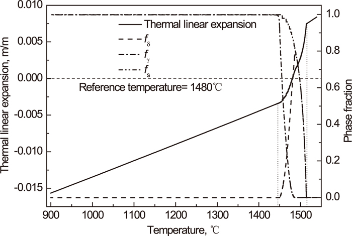
Taking place peritectic transformation is the striking feature of peritectic steel solidification and the direct cause of the shell giving rise to larger shrinkage than casting other steel in mold. Figure 2 shows the variations of phase fractions of δ, γ and solid with temperature during the peritectic steel solidification calculated from the solute microsegregation model under the mold cooling rate and the thermal linear expansion curve of the peritectic steel based on the reference temperature of 1480°C (which is the LIT* of the peritectic steel). The steel starts to solidify at the temperature of 1514°C, and begins the δ→γ transformation at 1487°C. Because of the change of lattice structure between δ and γ phases during the steel solidification, the thermal linear expansion in the temperature region of 1446°C–1514°C shows a significant decrease with the temperature decrease, which means that the shell in this temperature range will shrink severely. However, when the temperature decreases below 1446°C (solidus of the steel), the descent rate of the thermal linear expansion slows down.
As a result of the above solidification characteristics of the peritectic steel, the shrinkage profile of the solidifying shell at the position of 30 mm off the narrow face corner in the conventional slab mold to the direction of wide face midst along mold height is shown in Fig. 3(a). At the upper part of the mold (0–90 mm below meniscus), the shrinkage is small since the shell at this stage is rather thin and hot. Therefore, the shell maintains a good contact with the mold wall. However, when the shell moves down to the distances of 90 mm–300 mm below meniscus, the shell shrinkage is enhanced that the amount exceeds the compensation of the mold taper because the temperature of large proportion shell is in the range of 1446°C–1514°C, as seen from Figs. 8(a) and 8(b). Thus, the shell separates from the mold wall, and the large size gap between shell and mold forms. With the shell continuously moving down, the shrinkage becomes weak since the temperature of the most of solidifying shell is lower than 1446°C, seen from Figs. 8(c) and 8(d). The gap size between the shell and mold reduces gradually with the compensation of mold taper. When the shell moves down to the distance of 110 mm above mold exit, the compensation of the mold taper exceeds the shell shrinkage that the shell is forced to contact the mold wall tightly.

Figures 3(b) and 3(c) show the wear topography of mold narrow face copper plate of practical industrial production after casting 34690 tons of AH32 and AH36 (both of them are the high strength ship plate steel, and the compositions are approximate). The wearing area of the mold copper plate starts from the distance of 682 mm below the meniscus to mold exit. It is in a good agreement with the calculated results that the shell is forced to contact the mold wall tightly from the distance of 690 mm below meniscus to mold exit.
Figure 4 shows the deformations of shell transverse section at the distances of 100 mm, 300 mm, 500 mm and mold exit below meniscus. The deformed geometries of the shell were magnified by 5 times in the figures. As the result of above shrinkage characteristics of shell to the wide face midst in the mold, the shell deformation at mold upper part is quite small, as shown in Fig. 4(a), but it is rather severe at the middle part of the mold because the insufficient mold taper could not support the shell that leads to it be pushed to the mold wall by the molten static pressure, as shown in Figs. 4(b) and 4(c). Thus, the large size gap between shell and mold around the narrow face off-corner forms, and meanwhile the tensile stress in shell solidification front both around the corner and off-corner generates, which is the important factor giving rise to the slab around the corner and off-corners suffer corner and subsurface cracks during continuous casting. When the shell moves down to the distance below 500 mm from meniscus, the deformation becomes weak since the mold wall contacts the shell well, as shown in Fig. 4(d).
In addition, since the shell shrinks continuously to the direction of narrow face midst but lacks the mold taper compensation for shell wide face, the large size gap also forms around the shell wide face off-corner. As the effect of such deformation characteristics of solidifying shell, it easily leads to the thick air gap and mold flux film fill in the gap between the shell and mold both around the wide and narrow face off-corners, and causes the shell nonuniform heat transfer along shell circumference.
* Liquid Impenetrable Temperature, which was defined by Clyne
et al.40) to divide the mushy zone of shell solidification front into mass/liquid feeding zone and cracking zone. Usually, the temperature range consisted of ZDT and LIT is defined as brittle temperature range to estimate the cracking tendency of casting steel.
3.2. Heat Transfer and Temperature Distribution
During practical continuous casting, the shell heat transfer in mold is mainly determined by the interfacical heat transfer between shell and mold. The nonuniform distributions of air gap and mold flux film in the gap along shell circumference are the main factors leading to the shell nonuniform heat transfer. Therefore, revealing the laws of air gap formation and mold flux film distribution in the gap is an important part of describing the thermal behavior of shell solidifying in mold.
Figure 5 shows the formation characteristics of air gap around shell corner along the directions of mold height and circumference as the results of shell shrinkage and deformation behaviors in mold. The air gap foremost forms in shell corner at the distance of 160 mm below meniscus, and mainly concentrates in the regions of 0–20 mm and 0–10 mm nearby the wide and narrow face corners in the slab mold, respectively. On the wide face, as shown in Fig. 5(a), the air gap grows continuously at the upper part of the mold with the shell moving down, and grows acceleratively when it moves down to the distance of 550 mm below the meniscus because the gap size around shell wide face corner is broadened due to the strengthened squeezing between shell narrow face and mold, which causes the shell corner twist to the direction of shell narrow face midst. When the shell moves down to mold exit, the maximum thickness of the air gap reaches 0.80 mm at the corner.
As for the narrow face, the air gap just mainly forms at the distances of 160 mm–450 mm below meniscus and is much thinner than the wide face. At the upper part of mold, the air gap forms rather quickly and even exceeds the wide face. It reaches the maximum thickness about 0.17 mm at the distance of 300 mm below meniscus, and then decreases sharply since the shell shrinkage slows down and the mold taper compensates continuously. When shell moves down below the distance of 450 mm from meniscus, the air gap becomes stabile.
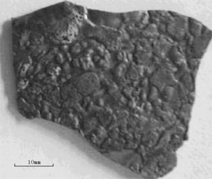
Figure 6 shows the distribution characteristics of mold flux film in the gap between shell and mold around shell off-corners at the distances of 100 mm, 300 mm, 500 mm below meniscus and mold exit. The measured data of the thickness of mold flux film around mold wide face corner was gotten from the practical industrial continuous casting that scraped the solid mold flux film from mold wide face that sticks on the copper plate hot face around the corner at mold exit after casting 4945 tons of high strength ship plate steel of AH36 (the simulated peritectic steel) under the casting conditions in Table 1, shown the topography in the following Fig. 7. At the upper part of mold, the mold flux films both around shell wide and narrow faces decrease gradually from the corners to the midst. Nevertheless, the distributions are relatively uniform that the differences of the thicknesses between the corners and the corresponding midst are just 0.20 mm and 0.32 mm, respectively, when shell moves down to the distances of 100 mm below meniscus. However, with the shell moving down continuously, the mold flux films completely solidify gradually from the corners to the midst, and thus the distributions show a trend that increase firstly and decrease then in the regions of 0–120 mm and 0–70 mm off the shell wide and narrow face corners as a result of the evolution of the solidifying shell deformation. The maximum differences of the thicknesses between the regions and the corresponding midst reach 0.81 mm at mold exit and 1.07 mm at 300 mm below meniscus, respectively. It greatly slows down the heat transfer of shell off-corners and arouses hot spots in these regions.
Figure 8 shows the transverse section temperature fields of strand and mold copper plate at the distances of 100 mm, 300 mm, 500 mm below meniscus and mold exit under the above heat transfer conditions of shell/mold gap. The temperatures of 1456°C and 1480°C correspond to the ZDT and LIT of the peritectic steel. The temperature of the strand at initial solidification stage is quite uniform across the section except for the corner, where the temperature decreases rapidly due to the two dimensional heat transfer, as seen in Fig. 8(a). However, with the shell moving down, the heat transfer both around shell corner and off-corner slows down gradually since the air gap formation and more mold flux film fill in the gap of these regions, as shown in Figs. 5 and 6. With the shell moving down to 300 mm below meniscus, the hot spots start to form in the regions of 10 mm–20 mm both off shell wide and narrow face corners, and expand to the regions of 10 mm–80 mm and 15 mm–60 mm off the wide and narrow face corners when the shell moves down to mold exit. The maximum temperature differences between the off-corners and the corresponding midst reach 120°C and 61°C, respectively.

Because of the obvious hot spots forming on both of shell wide and narrow face off-corners, the shell grows much thinner at these regions, especially for wide face off-corner, as seen from Fig. 9. Compared to the midst, the thicknesses of shell wide and narrow face off-corners are reduced 2.17 mm and 1.13 mm correspondingly at mold exit, respectively. It is should be noted that the thickness of the solidified shell is just about 15 mm at mold exit under the typical casting conditions of peritectic steel. Thus, the growth of the solidifying shell in the mold under the conventional mold taper is rather nonuniform. The weak shell at these regions becomes the vulnerable spots of cracking.26,32,41)

As the effects of above thermal and mechanical behaviors of shell solidifying in mold, the subsurface cracks that appear at the regions of 0–100 mm and 0–55 mm off shell wide and narrow face corners are often suffered during the practical continuous casting of the peritectic steel in the plant, as shown in Fig. 10, which the average occurrence rate of such defects during the time from January to July of 2012 reaches 16.948% by the statistics.
4. New Mold Taper Design and Application
In view of the main reasons of the slabs suffered the subsurface cracks are the large tensile stress in shell solidification front caused by the excessive deformation and the formation of hot spots on shell wide and narrow face off-corners resulted from the nonuniform distributions of air gap and mold flux film around the regions in the mold. Both of the two reasons are inflicted by the usage of improper mold taper of conventional linear constant narrow face with ignoring the wide face structure. In order to match the mold wall to shell shrinkage and uniformize the shell heat transfer along circumference, as well as reduce the wear of mold copper plate, a new slab mold taper for peritectic steel slab continuous casting is designed according to the characteristics of the shrinkage and heat transfer of shell in the mold in the present work.
4.1. Designing Scheme
By fitting the shrinkage profile of shell narrow face to the direction of shell wide face midst along the distance below meniscus, as shown in Fig. 3(a), the relationship between the profile and the distance can be written as
|
T
slope
={
0.00805h h≤90 mm
-12.856×exp(-h/1 339.07)-1.9815×exp(-h/63.4912)+13.2226 h>90 mm
| (1) |
Where,
Tslope is the shrinkage of shell narrow face, mm,
h is the distance below meniscus, mm. Intending to ensure the mold wall match the shell shrinkage just right without exerting excessive contact forces on shell, the non-linear slope of
Eq. (1) is adopted for mold narrow face.
Moreover, since the thick gaps with about 1.0 mm sizes between shell and mold around the off-corners of shell wide and narrow faces mainly concentrate on the regions of 0–120 mm and 0–70 mm off the corresponding corners under the conventional mold taper, the wedge-shape structures for mold wide and narrow face corners that apportion 1.0 mm to the corners slopes with linear increase from meniscus to mold exit and meanwhile reduce the slopes to 0 mm linearly from the corners to the baselines of 120 mm and 70 mm apart the corners of mold wide and narrow faces are introduced to restraint the thick air gap formation and mold flux film distribution in the gap around the regions, as shown in Fig. 11.
4.2. Shell Thermal and Mechanical Behaviors under New Mold Taper
4.2.1. Shell Shrinkage
Figure 12 shows the shell shrinkage profiles and the corresponding mold taper slopes at the narrow face corner and midst and the wide face corner along the distance below meniscus in the new mold. To the shell narrow face, the mold wall matches the shell shrinkage well since the non-linear slope of mold narrow face with wedge-shape structure on the corner is introduced. The maximum sizes of the gaps at shell narrow face corner and midst are just about 0.11 mm and 0.07 mm respectively at the distances of 150 mm–450 mm below meniscus. Thus, the mold wall supports the shell narrow face well. Similarly, because of the compensation of wedge-shape structure taper on shell wide face corner, the gap size around the corner is also greatly reduced that the maximum size decreases from 1.11 mm of using conventional mold to 0.37 mm, although the shrinkage is enhanced slightly since the heat transfer condition of shell narrow face is improved. Therefore, both the deformation of the solidifying shell and the sizes of shell/mold gap around the wide and narrow faces are greatly minimized in the new mold. It means that the tensile stress in shell solidification front and the thick air gap and mold flux film distribution around shell wide and narrow face off-corners are greatly reduced.

Figure 13 shows the comparisons of the distributions of air gap on shell wide and narrow face corners along casting direction in the conventional mold and new mold. In the new mold, the air gaps both on shell wide and narrow face corners are greatly reduced that the maximum thickness in shell wide face corner decreases from 0.80 mm of using conventional mold taper to 0.28 mm and the air gap on shell narrow face almost disappears. Furthermore, the distribution trend of the air gap on shell wide face corner is also changed greatly that it does not grow continuously along casting direction and accelerates at mold lower part again but just grows at middle part of the mold and then decreases with shell moving down.

Figure 14 shows the distribution characteristics of mold flux film around shell wide and narrow face off-corners at the distances of 100 mm, 300 mm, 500 mm below meniscus and mold exit in the new mold. The general distribution trends of the mold flux films both in shell wide and narrow faces are similar to that of using conventional mold taper that the mold flux films in the gap also increase firstly and decrease then along shell circumference directions from the corners to midst. However, both the thickness and the distribution of the thick mold flux film around shell wide and narrow face off-corners are greatly reduced. To the shell wide face, the maximum thickness of the mold flux film under new mold taper is 0.47 mm which 0.54 mm is reduced from 1.01 mm of using conventional mold taper, and the region of the thick mold flux film distribution is constringed from 0–120 mm to 0–40 mm from shell corner. As for shell narrow face, the mold flux film in the gap is reduced more greatly that the maximum thickness on the off-corner is just about 0.31 mm that 0.96 mm is reduced compared to using the conventional mold taper. It is beneficial for the shell uniform heat transfer.

The distributions of shell surface temperatures along the circumference at the distances of 300 mm, 500 mm below meniscus and mold exit in the new mold are shown in Fig. 15. With the reduction of air gap formation and uniform distribution of mold flux film in shell-mold gap, the temperatures of both shell wide and narrow faces are quite uniform although a slightly hot spot forms on the wide face off-corner with 18°C increase. However, it dose not exert any influence on the shell growth, as seen in Fig. 16. Thus, the susceptibility of shell cracking decreases because of the disappearance of hot spots along shell circumference.
Moreover, because the temperatures of shell corner and narrow face are greatly decreased by using the new mold taper, the strength of the solidified shell enhances accordingly, which is beneficial to withstand the ferro-static pressure and prevent the bulging of shell narrow face when the shell moves out the mold exit.
4.3. Applied Effectiveness of New Mold Taper
4.3.1. Improvement of Slab Subsurface Cracks
Figure 17 shows the occurrence rates of slab subsurface cracks in wide and narrow faces by using the new mold taper and conventional mold taper casting the peritectic steel in the plant under the same other casting conditions shown in Table 1. The cracking rate was counted in terms of the number of slabs appearing subsurface cracks over the total number of the casting slabs. During the experiment, the occurrence rates of the subsurface cracks around shell wide and narrow face off-corners are 17.338% and 10.916% under the conventional mold taper. However, by using the new mold taper casting the peritectic steel, the occurrence rates were greatly reduced both on shell wide and narrow face off-corners that the rates reduced to about 0.103% and 0.068% respectively because the tensile stress in shell solidification front is greatly reduced as the mold wall supports the shell narrow face well and the hot spots both around shell wide and narrow face off-corners are eliminated in the new mold.

The working life of the mold copper plate is another important factor need to be considered for designing the mold taper. Figures 18(a), 18(b) and 18(c), 18(d) are the wear topographies of mold copper plates under conventional mold taper and new mold taper after casting 34690 tons and 57450 tons peritectic steel, respectively. The wearing areas both under the conventional mold taper and new taper concentrate on the lower part of mold narrow face, and start from the midst firstly then expend to the corner gradually. Nevertheless, both the wearing sizes and thickness are different from each other. Under the conventional mold taper, the wearing area of the mold narrow face copper plate starts from the distance of 119 mm above the mold exit and the maximum wearing thickness is 3.61 mm at mold exit, while the wearing area just appears at the distances of 0–54 mm above mold exit and the maximum wearing thickness is 1.44 mm under the new mold taper. The average wearing thickness of mold narrow face copper plate decreases from 1.041×10⁻⁴ mm/ton steel to 2.507×10⁻⁵ mm/ton steel under the new mold taper.

In addition, it can be seen clearly from Fig. 18(c) that the copper plate of mold wide face almost has no wear during the experiment even though the wedge-shape structure was plated on the wide face corner. Therefore, the working life of mold can be greatly prolonged by using the new mold taper.
5. Conclusions
Based on the thermal and mechanical behaviors of solidifying shell in the peritectic steel slab continuous casting mold of using conventional mold taper, a new mold taper with non-linear slope narrow face and wedge-shape structures on both of wide and narrow face corners was designed. The thermal and mechanical behaviors and the applied effectiveness of using new mold tapers were analyzed. The results show that:
(1) Continuously casting peritectic steel slab under conventional mold taper, the compensation of mold taper at the distances of 90 mm–690 mm below meniscus is insufficient for matching the shell narrow face shrinkage, the shell deforms severely at these distances and gives rise to the solidification front generate large tensile stress. Air gap mainly forms in the regions of 0–20 mm and 0–10 mm nearby the wide and narrow face corners, and the thick mold flux film concentrates on 0–120 mm and 0–70 mm off the corners respectively in the mold. Both of them lead to the shell off-corners form hot spots. The tensile stress of shell solidification front and the hot spots result in the slab suffer great subsurface cracks during practical continuous casting.
(2) In the new mold, the mold walls match the shell shrinkages well. The air gap in shell wide face corner decreases from 0.80 mm of using conventional mold taper to 0.28 mm and almost disappears in shell narrow face. The maximum thickness of mold flux film around shell wide and narrow face off-corners are reduced 0.54 mm and 0.96 mm from using conventional mold taper, respectively, and the distribution are also greatly constringed. The shell grows uniformly in the new mold.
(3) Under the new mold taper, both the slab subsurface cracks and the wear of mold copper plate are greatly improved. The occurrence rates of slab subsurface cracks in the wide and narrow faces decrease from 17.338% and 10.916% of using conventional mold taper to 0.103% and 0.068%, and the size of the wearing area of mold narrow face copper plate is constringed from 0–119 mm to 0–54 mm above mold exit and the average wearing thickness decreases from 1.041×10⁻⁴ mm/ton steel to 2.507×10⁻⁵ mm/ton steel. The working life of the mold is greatly prolonged.
Acknowledgement
The National Outstanding Young Scientist Foundation of China (50925415), Fundamental Research Funds for the Central University of China (N100102001) and Postdoctoral Science Foundation of China (2012M510822) are acknowledged for supporting this work.
References
- 1) R. J. Dippenaar, I. V. Samarasekera and J. K. Brimacombe: ISS Trans., 7 (1986), 31.
- 2) B. G. Thomas and W. R. Storkman: Modeling and Control of Casting and Welding Processes, TMS, Warrendale, PA, (1988), 287.
- 3) B. G. Thomas, W. R. Storkman and A. Moitra: Proc. 6th Int. Iron and Steel Cong., ISIJ, Tokyo, (1990), 348.
- 4) Y. M. Won, T. J. Yeo, K. H. Oh, J. K. Park, J. Choi and C. H. Yim: ISIJ Int., 38 (1998), 53.
- 5) B. G. Thomas and C. Ojeda: ISSTech Steelmaking Conf., ISS, Warrendale, PA, (2003), 295.
- 6) C. S. Li and B. G. Thomas: ISSTech Steelmaking Conf., ISS, Warrendale, PA, (2003), 685.
- 7) A. Marcandalli, C. Mapelli and W. Nicodemi: Ironmaking Steelmaking, 30 (2003), 265.
- 8) B. G. Thomas, M. Dziuba and G. D. Gresia: 14th IAS Steelmaking Conf., IAS, Buenos Aires, (2003), 87.
- 9) Y. Meng and B. G. Thomas: Metall. Mater. Trans., 34B (2003), 685.
- 10) Y. Meng, C. S. Li, J. Parkman and B. G. Thomas: Solidification Processes and Microstructures: A Symp. in Honor of Wilfried Kurz, TMS, Warrendale, PA, (2004), 33.
- 11) Y. Matoba, K. Okamura, T. Murakami and K. Yamamoto: JSME Int. J., 48 (2005), 163.
- 12) Y. C. Wang, L. G. Zhu, S. R. Liu and Y. H. Peng: Steelmaking, 22 (2006), 48.
- 13) Y. P. Sheng, X. D. Kong, J. Y. Liu and Y. L. Yang: Chinese J. Mech. Eng., 42 (2006), 110.
- 14) F. D. Li, B. F. Wang, J. C. Li and J. G. Wang: Contin. Cast., 17, (2009), 1.
- 15) J. G. Wang, B. F. Wang, F. Dong, J. C. Li and F. D. Li: Contin. Cast., 17, (2009), 10.
- 16) S. W. Cai, T. M. Wang, J. Li, J. J. Xu, Y. Y. Du, Z. Q. Cao and T. J. Li: Special Cast. Nonferrous Alloy., 29 (2009), 709.
- 17) T. M. Wang, S. W. Cai, J. Li, J. J. Xu, Z. N. Chen, J. Zhu, Z. Q. Cao and T. J. Li: China Foundry, 7 (2010), 61.
- 18) S. W. Cai, T. M. Wang, J. J. Xu, J. Li, Z. Q. Cao and T. J. Li: Mat. Res. Innovat., 15 (2011), 29.
- 19) S. N. Berdnikov, A. E. Pozin, A. A. Podosyan and K. N. Vdovin: Steel Transl., 41 (2011), 410.
- 20) S. N. Berdnikov, A. E. Pozin, A. A. Podosyan, A. S. Berdnikov, V. A. Mokhov and K. N. Vdovin: Steel Transl., 42 (2012), 180.
- 21) A. V. Fedosova, E. A. Kazachkov, E. A. Chichkarev, V. V. Kislitsa and O. B. Isaev: Steel Transl., 40 (2010), 833.
- 22) T. Wang, J. Li, Z. Chen, L. Wu, Z. Cao and T. Li: Ironmaking Steelmaking, 40 (2013), 25.
- 23) B. G. Thomas: ISS Trans., 16 (1989), 1.
- 24) B. G. Thomas: ISIJ Int., 35 (1995), 737.
- 25) B. G. Thomas, A. Moitra and R. McDavid: ISS Trans., 23 (1996), 57.
- 26) H. N. Han, J.-E. Lee, T.-J. Yeo, Y. M. Won, K.-h. Kim, K. H. Oh and J.-K. Yoon: ISIJ Int., 39 (1999), 445.
- 27) C. H. Moon and S. M. Hwang: Int. J. Numer. Meth. Eng., 57 (2003), 315.
- 28) J. M. Risso, A. E. Huespe and A. Cardona: Int. J. Numer. Meth. Eng., 65 (2006), 1355.
- 29) S. Koric and B. G. Thomas: J. Mater. Process. Technol., 197 (2008), 408.
- 30) Z. Z. Cai and M. Y. Zhu: Acta Metall. Sin., 47 (2011), 671, 678.
- 31) Z. Z. Cai, M. Y. Zhu and Q. K. Liang: 4th Int. Conf. on Modelling and Simulation of Metallurgucal Processes in Steelmaking, Steel Institute VDEh, Düsseldorf, (2011), 1.
- 32) Z. Z. Cai, W. L. Wang and M. Y. Zhu: Mater. Sci. Tech. Int. Conf., MS&T, Pittsburgh, (2012), 61.
- 33) L. Anand: Trans. ASME, 104 (1982), 12.
- 34) S. B. Brown, K. H. Kim and L. Anand: Int. J. Plast., 5 (1989), 95.
- 35) Z. Z. Cai and M. Y. Zhu: Acta Metall. Sin., 45 (2009), 949.
- 36) Y. Ueshima, S. Mizoguchi, T. Matsumiya and H. Kajioka: Metall. Mater. Trans., 17B (1986), 945.
- 37) R. Saraswat, D. M. Maijer, P. D. Lee and K. C. Mills: ISIJ Int., 47 (2007), 95.
- 38) A. Yamauchi, T. Emi and S. Seetharaman: ISIJ Int., 42 (2002), 1084.
- 39) H. Nakada, M. Susa, Y. Seko, M. Hayashi and K. Nagata: ISIJ Int., 48 (2008), 446.
- 40) T. W. Clyne, M. Wolf and W. Kurz: Metall. Mater. Trans., 13B (1982), 259.
- 41) J. K. Brimacombe and K. Sorimachi: Metall. Mater. Trans., 8B (1977), 489.