Regular Article
Experimental and Numerical Investigations on Non-metallic Inclusions Distribution in Billets Casted at a Multi-strand Continuous Casting Tundish
2013 年 53 巻 11 号 p. 1983-1992
詳細
2013 年 53 巻 11 号 p. 1983-1992
Modern tundishes plays an important role of refining treatments to improve the quality and purity of casted steel. Purity of steel is defined by the non-metallic inclusions in the steel product, including their size, quantity, distribution, chemical composition and mineralogy. The aim of presented studies was to investigate the number and distribution of non-metallic inclusion in individual billets casted in a six-strand tundish. The industrial measurements, performed during stable production conditions at the continuous steel casting (CSC) plant, were performed for different tundish working space configurations. Analysis of the size and number of non-metallic inclusions has been done on the metallographic samples using light microscope. Experimental studies were supported with numerical simulations using large eddy simulations (LES) method. A modified boundary condition describing inclusion separation at the liquid steel surface was implemented in commercial code AnsysFluent.
Experimental results concern size distribution of inclusions in billets for current tundish configuration showed big differences between casted ingots. Numerical results shown the domination in the number of inclusions occurring in the nozzles number 3 and 4 (for basic tundish configuration) and in the nozzles number 2 and 5 (for tundish with turbulence inhibitor). The reason for that is the change in configuration tundish working space, that has an impact on the flow field inside the tundish. Experimental measurements performed for proposed modified tundish configuration (with turbulence inhibitor) shown that those differences are much smaller, which in consequence has an influence in higher quality of continuously casted ingots for individual strand of CSC.
Besides the basic functions of the tundish for continuous casting of steel, modern tundishes plays also an important role of refining treatments to improve the quality and purity of cast steel.1) Purity of steel is defined by the non-metallic inclusions in the steel product, including their size, quantity, distribution, chemical composition and mineralogy. Since the inclusions are lifted by the liquid steel, therefore it is necessary to analyze the structure of liquid steel flow, which is responsible for the transport and separation of non-metallic inclusions. Investigation of the steel flow field in the tundish or removing of non-metallic inclusions in an industrial environment is - due to the high temperatures of the process and the opacity of the liquid steel - difficult, and in some case even impossible to do. Due to those limitations experimental studies are supported by the research done on the water models and numerical studies with the use of computational fluid dynamics tools.
The flow field inside the tundish and accompanying inclusions separation process is strongly investigated with numerical modeling. Numerous studies can be found in literature. The present state of the Computational Fluid Dynamics (CFD) techniques allows calculating the fluid flow in tundish with the satisfying accuracy. This is confirmed by a good agreement in flow fields predicted mathematically and measured with laser-optical method done on the water models.2) For turbulence modeling (for RANS method), the standard or realizable k-ε models are mostly used.3,4)
On pre-calculated turbulent flow field, transport of disperse phase (non-metallic inclusions) is performed. In Euler-Lagrange approach5,6) the movement of each inclusion is treated separately and its trajectory is calculated by integrating local velocity. The differential equations, describing the motion of inclusions in liquid steel, considers the different forces acting on particle in fluid, such as drag force, buoyancy force, added mass force and additional forces. In order to simulate the effect of random movement of particles due to turbulence a Discrete Random Walk (DRW) model is very often used7,8,9,10,11) that is known as a stochastic model.12)
In the available literature the attention is drawn to the proper selection of boundary conditions for the non-metallic inclusions. In most studies, the limitation for the Lagrangian model are the inclusions (their number and size) injected to tundish with the steel through the inlet boundary condition. In turn, on the interface between metal and slag it is assumed that the inclusions are captured by the slag, so the perfect absorption is assumed. However, impact of non-metallic inclusions on the interface of liquid steel and refractory lining is assumed to be an elastic reflection, excluding adhesion and sintering. Non-metallic inclusion can only leave the tundish through the outflow surface with liquid steel to the mold.7,8,13,14,15,16)
Those conditions are quite far from reality, as the impact of the inclusions with distinct phases of the interface is not being realized by a perfect scenario. The effectiveness of such a collisions are resolved dynamically and they strongly depend on the phenomena that occurs on interface.
Non-metallic inclusions are modeled as an ideal spheres with different size and densities. With the assumptions, the solution of the flow equations with the boundary conditions allows to find the path and the distribution of non-metallic inclusions in liquid steel in the tundish during continuous casting. Confirmation can be found in results of numerous authors,8,17,18,19,20,21) where the motion of different non-metallic inclusions have been investigated in the steel flowing in the tundish.
These studies have shown that critical velocity for rising nonmetallic inclusions affect the removal of non-metallic inclusions in the tundish. Calculations performed by Sinha and Sahai21) confirm better capture by the slag inclusions of size greater than 120 μm rather than small inclusions (smaller than 40 μm). The reason for that is the density of inclusions. Kaufmann et al.19) have shown that, only 10% of inclusions with diameter 20 μm flows out from the liquid steel as a result of buoyancy force. Sinha and Sahai21) postulate that major role for mechanism of collision growth have non-metallic inclusions of small size. Turbulent flow favors such a kinetic growth, which justifies the influence of turbulence on the flow structure in steel in tundishes.
The influence of the devices that modify the flow of liquid steel - Flow Control Device (FCD) - have been investigated by numerous of researchers and published in journals.8,9,10,13,14,22) The result of the observation is that the use of dams, wires with or without filters, turbulence inhibitors or gas curtines – reduces the dead zones in the tundishes and increases the average residence time of liquid steel staying in the tundish. In the literature9,10,13,14,16) a significant improvement in the evolution of inclusions has been shown that is influenced by a combination of FCD – different combination of dams, wires, turbulence inhibitors and gas curtines. The combination of FCD directs the flow of liquid steel to the surface of metal-slag interface, increasing the permanent release of non-metallic inclusions in the metal phase.
The studies9,14) proved that large non-metallic inclusions are influenced by different mechanism - but tundish working space configuration has no significant effect on the removal of inclusions of small size. One can also consider if the capacity of the tundish can affect the growth and separation of inclusions.
In the present work, experimental and numerical studies to investigate the distribution and separation of non-metallic inclusion in steel produced in one of a steel plant (in Poland) were performed. For investigated steel grade, a typical type of tundish is a multi-strand tundish. The industrial measurements, performed during normal working conditions at the Continuous Steel Casting (CSC) plant, were performed to obtain a number and size distribution of inclusions in individual strands, for different tundish working space configurations. Analysis of the size and number of non-metallic inclusion has been done on the metallographic samples using light microscope Nikon Eclipse Ma 200.
The literature review and own experience (gained over the last 10 years) reveals the various levels of sizes of non-metallic inclusions in the investigated steels. The changes depends on the type of steel, and over the years along with the technological progress that leads to higher purity of steel (reducing the number of inclusions of large size). For these reasons, it is necessary to identify the critical size of inclusions for the modeled process conditions, including steels, which are the subject of research. Numerical simulations are carried out with the finite-volume commercial code AnsysFluent, using numerical method based on the Navier-Stokes equations. It is currently wide used in comprehensive analysis of a commercial plants. In numerical modeling, a choice of a proper turbulence model is crucial as it has a great impact on the flow structure of the fluid in the analyzed test facility and trajectories of non-metallic inclusions carried by the liquid steel. In the analysis of the turbulent flow using RANS method (Reynolds-averaged Navier-Stokes equations) one get the averaged values. In case of LES method (Large Eddy Simulation), which was used to carry out present numerical simulations, all the large turbulent scales are solved directly and only the small scales, that are smaller than the filter size are modeled. From those simulations one get also the information about the instantaneous velocity field inside the tundish. Additionally, authors introduced to the existing commercial software parts of their own code through the users defined functions, that describe the inclusion separation at the liquid steel surface. Separation of the inclusions due to flotation is considered here since it is the dominating mechanism of particle removal in the tundishes. Configurations of inside buildings (flow control unit) for the tundish working space analyzed during the research has been developed as a result of previous modeling studies and industrial research.23)
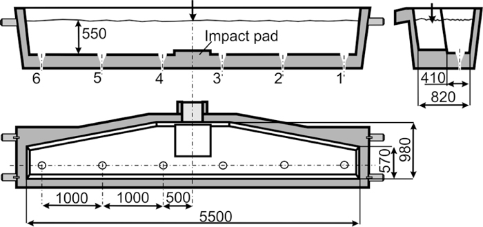
The subject of this study is a CSC tundish operating in a Polish steel plant. This is a trough-type tundish with six nozzles and nominal capacity of 15-tons. It is used for casting ingots intended for production of small cross-section rolled products. It is symmetrical with respect to its central cross-section. The basic refractory lining is made up of andalusite tiles, and the working layer is made up of a high-magnesite gunite mix. In its base configuration the tundish is equipped with an impact pad. During normal working conditions the tundish is used for sequence casting with more than ten heats. The technological operating conditions of tundish, as used in numerical simulations, are given in Table 1. Figure 1 shows the scheme of analyzed tundish with its major dimensions.
| Parameters | Value | Unit |
|---|---|---|
| nominal capacity | 15 | ton |
| molten steel level | 550 | mm |
| shroud diameter | 50 | mm |
| nozzle diameter | 17 | mm |
| number of tundish nozzles | 6 | – |
| casting speed | 1.7 | m/min |
| slab section | 160 × 160 | mm |
| inlet temperature | 1823 | K |
Tundish configurations before the optimization.
The first step has been taken to diagnose the state of the existing tundish operation (Fig. 1). In the next step, diagnose of other two variants of tundish working space modifications (Fig. 2) was performed.
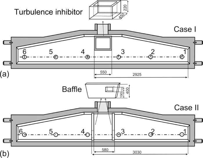
Schematics of the proposed tundish working space configurations: (a) turbulence inhibitor, (b) notched baffles.
The reason for undertaking those research were the adverse hydrodynamic conditions in the tundish in basic configuration without any buildings in the tundish working space. Thus the quality of the continuously cast billets did not meet the requirements. As a result of the research23) a buildings in the tundish working space has been proposed (turbulence inhibitor and notched baffles).
Due to this modification a zone has been separated in the tundish (with increased turbulence) whose task is to reorient the flow of the liquid steel stream. Research show23) that proposed configuration resulted in a clear separation of the inlet zone from the outlet zone, therefore a reduction in the transition zone has been obtained, increasing the share of plug flow. To conclude, the buildings in the tundish working space improved hydrodynamic conditions prevailing in the investigated tundish, which was confirmed by industrial research.23)
Those studies are continuation of the performed research and present the impact of modifications in the tundish working space for quality of continuously casted ingots.
The study of the size of non-metallic inclusion has been done on the metallographic samples using light microscope Nikon Eclipse Ma 200 that has a possibility of observation of the reflected light in the techniques of bright and dark field observation, the full scale of polarized light, as well as using Nomarski contrast. The range of possible use of magnification is 50 to 3000 times. The microscope is connected to the computer with the software for data acquisition and NIS-Elements analysis. The device used for analysis is presented in Fig. 3.
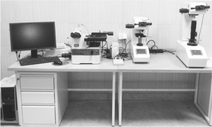
Apparatus used for research: Optical microscope Nikon Eclipse MA-200 – with the software for data acquisition and NIS-Elements analysis.
From continuously casted ingots (billets 160 × 160) casted on the individual strands (number 1, 2 and 3) slices were prepared for the same length of ingot. Then a samples has been taken with the dimensions 53 × 28 mm. Research has been done on the metallographic specimen samples. Figure 4 shows the view of the sample and place at the billet where the sample has been taken.
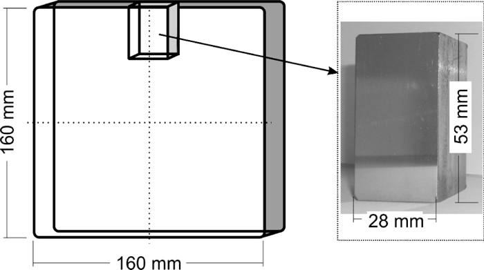
View of the sample and the place for taking the sample.
NIS-Elements D software has been use for analysis of number of inclusions, that allows to perform investigations and archive data from the large area. Due to the large size of the samples, each of it has been divided into six measuring zones across the measurement lines with the dimensions 1.54 × 1.22 mm2 (Fig. 5). In order to obtain satisfactory amount of data, from a statistical point of view, each measuring area has been analyzed with the magnification of 200 times and consisted of 16 images. Merged images gave the measurements areas of 1.54 × 1.22 mm2 (11-32).
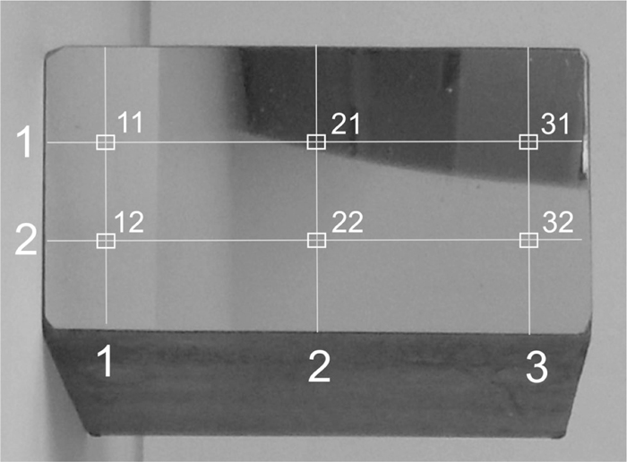
View of the sample prepared to analysis.
Analysis of each of six areas using NIS-ElementsD software was based on the principle of separation based on the color difference between inclusions and metal. This type of analysis could not be performed on the rough samples.
In LES method (Large Eddy Simulation) a spatial filtering is used to filter out all the scales smaller than the filter size. Using the density-weighted averaging, filtered variables can be written in the form:
| (1) |
| (2) |
| (3) |
| (4) |
| (5) |
| (6) |
| (7) |
| (8) |
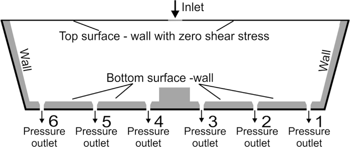
Boundary conditions set for numerical simulations of the fluid flow.
Detailed boundary and operating conditions which correspond to the conditions of the industrial process can be found in Table 2.
| Parameters | Value | Unit |
|---|---|---|
| liquid steel density | 7010 | kg/m3 |
| liquid steel dynamic viscosity | 0.007 | kg/m·s |
| inlet velocity | 2.2 | m/s |
| inlet temperature | 1823 | K |
| specific heat | 821 | J/kg·K |
| thermal conductivity | 30.5 | W/m·K |
| heat flux through side walls/bottom | –2.6 | kW/m2 |
| heat flux through slag cover | –16 | kW/m2 |
| inclusion density/Al2O3/ | 3960 | kg/m3 |
The computational domain discretization has been made by means of the computational mesh consisting of over one million control volumes for all tested cases, with the node distances of about 15 mm. Computational grid set at walls of the tundish working space for considered cases are shown in Fig. 7. The mesh is finer in the inlet and outlets regions.
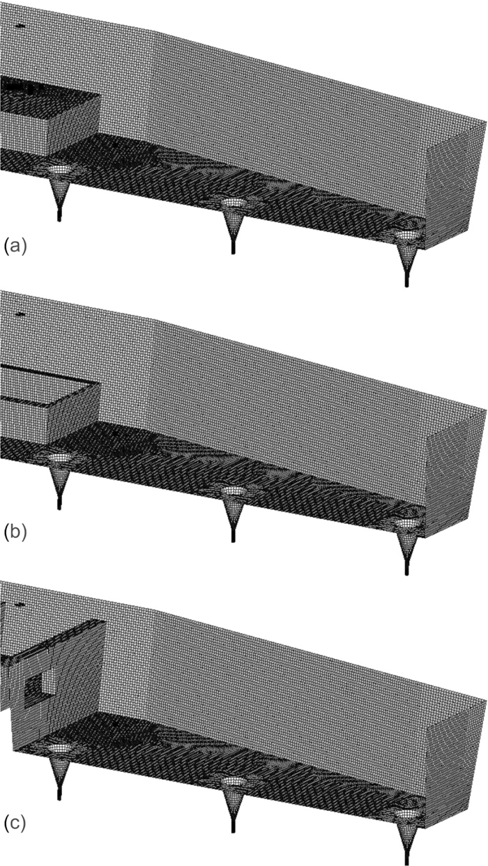
Computational grid set at walls of the tundish working space (a) tundish basic configuration, (b) Case I, (c) Case II.
Computations were carried out for steady state (stable production) casting conditions. For the computation of the liquid steel flow through the tundish, boundary condition of “no-slip” type was adapted for all walls, using the so called “wall function”. In the computations, the steel free surface was assumed as a flat surface – a wall with zero shear stresses. Numerical simulations have been performed on the computational clusters in Academic Computer Centre. Each configuration has been calculated on four processors for about three months (such a long computational time was needed to obtained final solution). First RANS simulations have been done to obtaine converged solution for velocity field. After that unsteady LES simulations have been performed for 400 seconds with unsteady statistics taken for the last 300 seconds.
4.2. Non-metallic Inclusion Removal ModelInclusions travel through flow field calculated with LES method. In industrial process non-metallic inclusions come to the tundish as deoxidization products together with steel from the ladle or/and are the product of tundish lining erosion or/and slag re-entering the melt. In this work only inclusions that originate as deoxidization products are considered. In performed numerical simulations inclusions come to the tundish with liquid steel, with the same initial velocity as steel. Inclusions are assumed to be spherical and their density ratio to liquid steel equals about 0.56. Presented investigations concentrate on inclusion separation due to flotation. The results do not include other mechanisms of inclusion removal. Therefore inclusions are reflected from all solid surfaces and can leave tundish only through one of the outlets or can be separated at the steel-slag interface (see Fig. 8). Coalescence of inclusions is not considered here.

Boundary conditions set for disperse phase - modified boundary condition (UDF).
The results presented here are the part of a big project concentrated on optimization of the tundish geometry and technology for casting billets with high purity and very similar quality/parameters at each strands. The differences in ingot quality casted at different strands for the former industrial six-strand tundish configuration, has been the basis for undertaking such investigations. The aim of the performed studies was to improve the casting conditions by proposing optimal equipment of the tundish working space. The results from previous work indicate that FCD which allocate from tundish working space a separate region (with higher turbulence) results in increasing share of dispersed plug flow and a decreasing share of the dead volume flow, with a practically unchanging share of well-mixed volume flow in the modified tundish. This should, in turn, enhance inclusions removal to covering slag. Such a flow control device is i.e. turbulence inhibitor or baffles.
5.1. Plant InvestigationsBaumann probe done on the square probes 160 × 160 (ingot imprint) shows the number of inclusions and sulphide pollutions. Analyzed samples has been determined as: A1–A3 (basic tundish configuration), B1–B3 (configuration Case I - turbulence inhibitor). The study has shown large differences in the amount and distribution of impurities in the analyzed material. Probe A2 (Fig. 9) is the most polluted one throughout the volume and therefore is taken as a reference probe. Analysis of the reference probe shows the highest impurities above and below the central part. The second area with high number of impurities is the near wall zone of the crystallizer at the entire length of the wall under the frozen crystals zone. Based on the above analysis, a cut samples has been chosen for quantitative analysis.
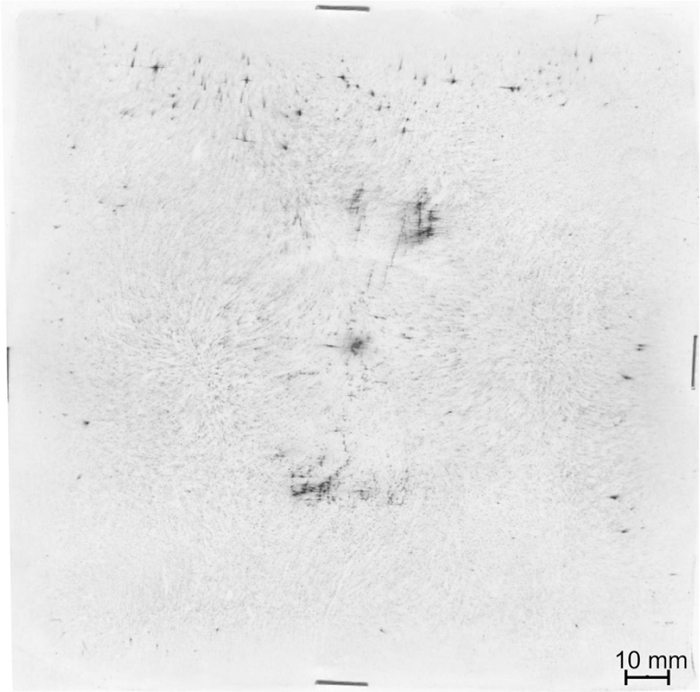
Ingot imprint (160 × 160) – Baumann probe; A2.
Figure 10(a) shows an example of metallographic ingot sample designated as 289 from area 11 from strand 1. Photomicrograph covers an area of 1.54 × 1.22 mm2 that corresponds to 16 photos (4 × 4). The following figure shows the same sample after applying the mask measurement. Attention is drawn to very clearly outlined inclusions and very good representation of the real areas of precipitates.
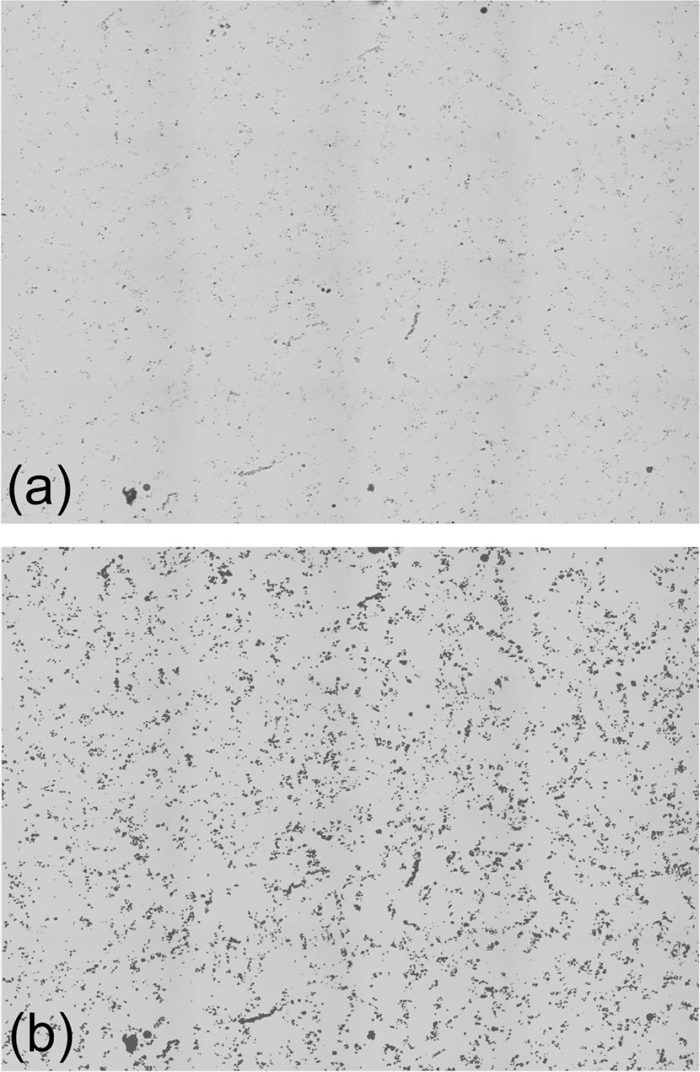
View of ingot sample designated as 289 from area 11 from strand 1 (magnification 200×): a) ingot with inclusions, b) the same area with mask measurement.
Obtained statistical data of the analyzed samples are shown in Figs. 11 and 12.
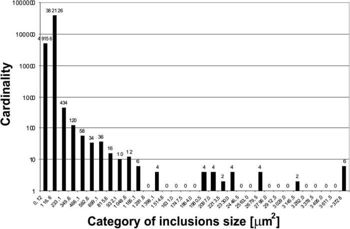
Size distribution of inclusions for the whole range, example probe; basic tundish configuration.
Figure 11 shows the distribution of inclusions obtained from one of the analyzed samples. This distribution is representative for the rest of the analyzed samples. Results show that inclusions with high impact for the analysis have an area up to 1000 μm2, therefore further charts show a narrow size range of non-metallic inclusions.
Figure 12 show distribution of sizes of inclusions taking into account the shares for different strands. Data were counted for each measurement area (see Fig. 5) and the sum over the classes has been taken.
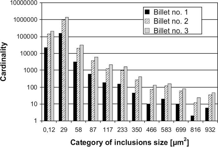
Size distribution of inclusions for current tundish configuration.
From Fig. 12 it can be seen that the highest amount of inclusions was measured in a probe taken from billet casted at nozzle no. 3. The reason for that can be a short circuit exist between inlet and nozzle no. 3, which is the nearest to the inlet (see Fig. 1). The highest distance between inlet and nozzle the lowest number of inclusions in a billet. The direct flow of the melt to mold (like in case of nozzle no. 3) do not insures enough time for separation of small inclusions and is probably the main reason for differences in quality of the billet casted at individual strands.
5.2. Numerical InvestigationsIn this section, the flow field in the tundish obtained using LES method is used to calculate inclusions trajectories in liquid steel. First, the results of the flow field obtained with numerical simulations are shown. Mean velocity vectors distributions and instantaneous temperature fields for three considered tundish configuration were obtained and are presented in Figs. 13 and 14. The results are presented for the cross section passing through the tundish nozzles.
Liquid steel velocity vectors: (a) tundish basic configuration, (b) Case I, (c) Case II.
As it can be easily seen form Figs. 13 and 14, installation of a flow control device in the tundish working space has strong influence on the liquid steel flow structure and in turn on temperature distribution in tundish. Those changes should also influence non-metallic inclusion transport in the tundish and separation from liquid steel.
Currently working tundish is characterized by relatively high velocities of the fluid. In the tundish working space not much rising streams can be found; they are essential for growing non-metallic inclusions and removing them to the covering slag, due to flotation. With installation of FCD more rising streams can be observed which should improve the liquid steel inclusion refining conditions. Figure 14 shows the liquid steel temperature distribution for investigated cases. The liquid steel temperature differences are very low, however, it can be noticed that in case of basic tundish configuration and those with turbulence inhibitor, liquid steel temperature is more homogenous.

Liquid steel instantaneous temperature, in K: (a) tundish basic configuration, (b) Case I, (c) Case II.
Based on the experimental results of the non-metallic inclusions distribution in testing samples of steel, the numerical simulations have been performed for selected sizes: 1, 2, 5, 10, 20 and 30 μm. Inclusions are released from the inlet surface and their trajectories are calculated with discrete random walk model. Injection of inclusions with one group size is repeated and the total separation rate is an average value form about 1000 particles.
Analysis of probes taken from billets shows that prevalent sizes of inclusions do not cross 30 μm, which can be a suggestion that biggest inclusions are separated in tundish or mould. Also the results of experiments performed with water models25,26,27) concerning removal of particles (used to simulate the inclusions) from liquid in tundishes shows that separation of such a small (less than about 30 μm) inclusions, is very low. Those facts were the main reason for searching some boundary condition (other than standard) describing the inclusion separation at the steel-slag interface. In its presented form velocities of fluid and inclusion in the vicinity of this border are considered. The critical velocity of fluid, above which the particle can be re-entrained to fluid, are derived from a force balance according to Engh:28)
| (9) |
The velocity ub has been included in the boundary condition at the surface via an User Defined Function (UDF). Boundary condition described above has been previously validated with water model results obtained with one-strand tundish water model.29)
Figure 15 shows numerically predicted results of inclusion flowing out through all tundish nozzles, for currently working tundish configuration, calculated with standard boundary condition (trap) set at the steel surface and with modified boundary condition. In the first simulation a standard (trap) boundary condition is used for inclusion separation which assumed that all inclusions which reach the covering slag surface are separated.
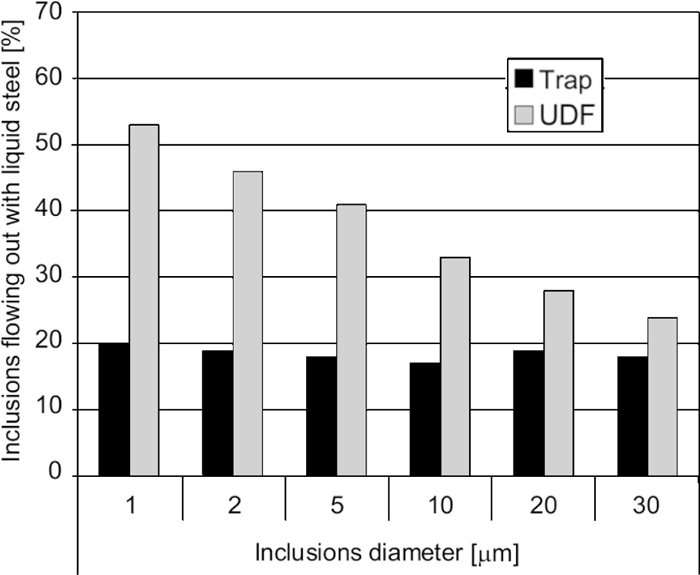
Numerical predictions of inclusions flowing out with liquid steel from the tundish, modeled with standard (trap) and modified (UDF) boundary condition; tundish basic configuration.
It can be seen, that the number of inclusions leaving tundish obtained with standard boundary condition is very low for all inclusion diameters. These results do not correspond to the values of inclusion numbers found in the billets. It is expected that the number of the inclusions with considered diameters is much higher than predicted numerically. In case of simulations with modified boundary condition, the number of the smallest inclusions (1–10 μm) flowing out with liquid steel are much higher, which means that they flow with the fluid and are nearly not separated at the steel surface.
Although this condition still needs future work, i.e. to include additional forces, the results obtained with the UDF function gave a better agreement with the experimental results. On this basis the modified boundary condition is used to predict the inclusions separation phenomena in the investigated tundish and to calculate the influence of considered flow control devices on particle separation due to flotation.
The results of inclusion flowing out through the nozzles predicted numerically (with modified boundary condition for inclusion separation at the liquid metal surface) for former tundish configuration are shown in Fig. 16.
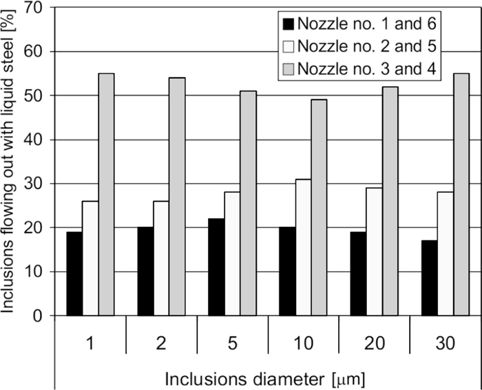
Numerical predictions of inclusions flowing out with liquid steel through individual nozzles - tundish basic configuration.
Figures 17, 18, 19 shows the influence of proposed flow control devices on inclusions changes in steel leaving the tundish depending on individual strands and in general. Numerical simulations results performed for basic tundish configuration shows the highest differences in casted ingots quality (characterized by the number of inclusions) and that internal nozzles (no. 3 and 4) introduces the highest amount of inclusions to the molds. After application any of the proposed FCD, this differences are not as big as for pure configuration and by installing an turbulence inhibitor, the differences are the lowest, which as a consequence has a strong impact on more uniform quality of the continuously casted billets.
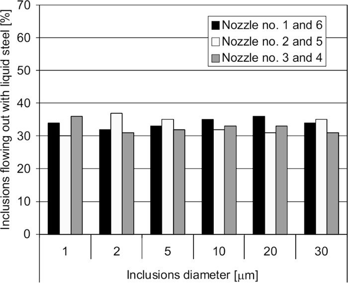
Numerical predictions of inclusions flowing out with liquid steel through the individual nozzles - tundish equipped with an turbulence inhibitor.
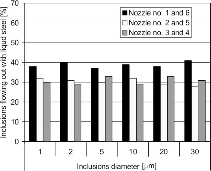
Numerical predictions of inclusions flowing out with liquid steel through individual nozzles - tundish equipped with baffles.
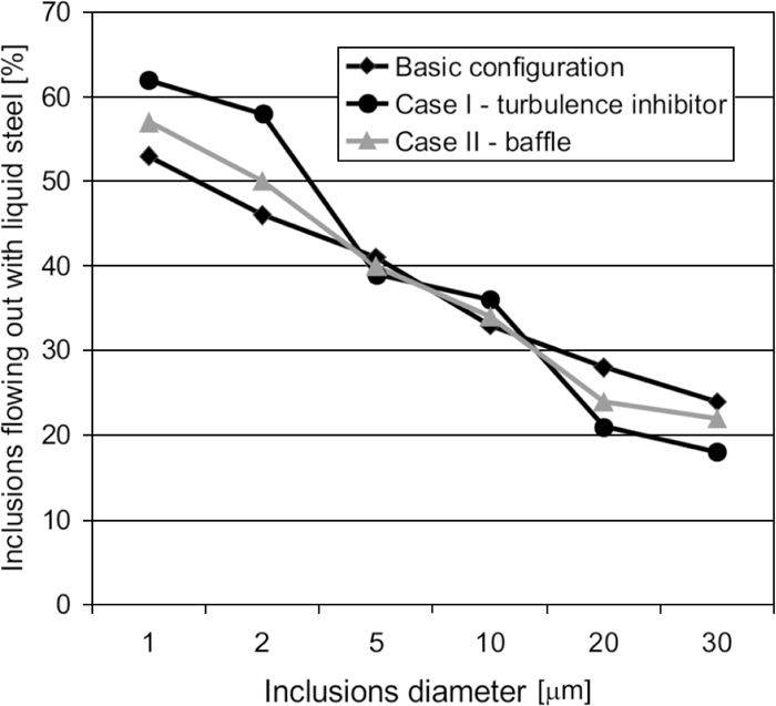
Numerical predictions of inclusions flowing out with liquid steel through individual nozzles – different tundish configurations.
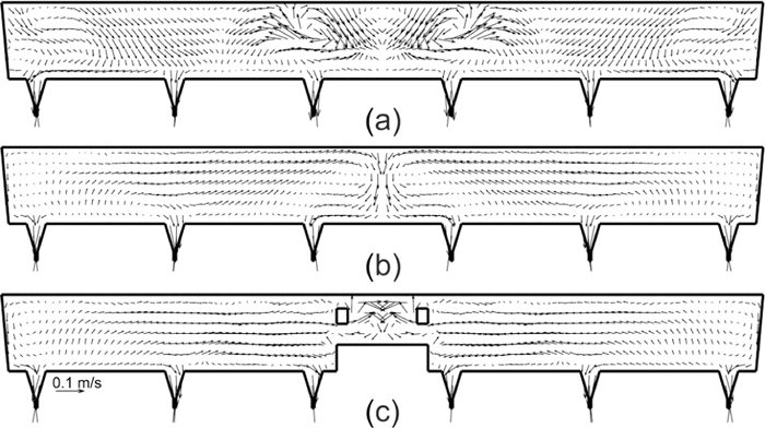
For analyzing the simulation results of inclusion removal, additionally fluid flow topology in the tundish working space for test cases are shown in Fig. 20. Figure 20(a) shows that in the basic tundish configuration an impact pad installed at the tundish bottom directs liquid steel stream to the nearest outlets (no. 3 and 4). It creates a short circuit between inlet and those nozzles. A direct flow of the part of the liquid steel can be the reason of decreasing the quality of billet casted at this strands since small inclusions are transported with steel.
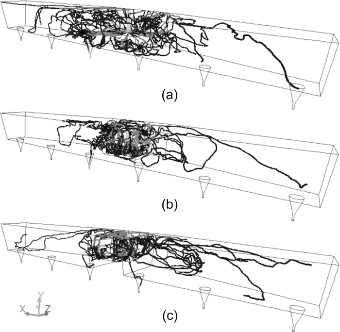
Liquid steel flow topology in the investigated tundish: (a) tundish basic configuration, (b) Case I, (c) Case II.
The situation is changing if the incoming steel meets a flow control device. In both considered cases (Case I and II), FCD directs the fluid to the steel-slag interface which should help to remove inclusions due to their flotation to the covering slag. It is expected that FCD’s help to improve steel quality and decrease the differences between individual strands. The difference between turbulence inhibitor (Case I) and notched baffles (Case II) is that in case of notched baffles - Fig. 20(c) the fluid is directed to the farther outlets (no. 1 and 6). This is the reason why one observe more inclusions leaving the tundish through this outlets (Fig. 18). In case of turbulence inhibitor - Fig. 20(b), there is no such evident tendency and inclusions leave the tundish through all outlets more uniformly (Fig. 17).
One should noticed that inclusions diameters found in probes taken from billets are between less than 1 μm up to about 30 μm. Non-metallic inclusions with such a size are very difficult to remove from liquid steel in the tundish.
Similar like in studies9,14) it can be noticed that tundish working space configuration has no significant effect on the removal of inclusions of small size, like considered here (less than 30 μm).
The results show that tundish configuration with turbulence inhibitor installed in the tundish working space can bring the better distribution of inclusions number for individual strands.
5.3. Additional Plant InvestigationsDue to the facts confirmed numerically the investigated industrial tundish was equipped with an turbulence inhibitor proposed and implemented in numerical model. Additional industrial measurements were carried out, to verify the simulation study results. The tests were performed with the same procedure as previous (for tundish with former configuration), for the three billets casted from three different strands. The results of this tests are shown in Fig. 21.

Size distribution of inclusions, tundish equipped with turbulence inhibitor.
Comparing the experimental results shown in Fig. 21 with experimental results obtained for former tundish configuration (Fig. 12) one can notice a small rise of inclusions number for each category of inclusion size. In numerical simulations, presented in Fig. 19, one can observe that the number of inclusions flowing out from the tundish with liquid steel, in case of turbulence inhibitor, is higher or almost the same as for basic tundish configuration, for inclusions with diameters 1 to 10 μm. For bigger inclusions, 20 and 30 μm, numerical predictions show that the number of inclusions leaving tundish is lower for the tundish equipped with turbulence inhibitor. The reason for that can be that small inclusions are characterized by the lower buoyancy force and they follow the fluid. In consequence any changes of the flow structure cause the different conditions for inclusions removal. The reason for differences observed between numerical predictions and experimental results can be also the fact that numerical model considers only one mechanism of inclusion removal in the tundish. The results may indicate, that tundish with turbulence inhibitor (this particular construction and geometry type) is not an optimal solution for investigated tundish. In general, the use of turbulence inhibitor in the tundish should help to improve the purity of steel (removal of non-metallic inclusions). However, according to the study presented in the worldwide literature, plate of this type should be individually adapted to the geometry of the investigated object.
One should also keep in mind that inclusions with diameters considered here present in steel product are not very harmful. More important is the fact that the distribution of inclusions present in individual billets casted at different strands are very similar for tundish configuration with turbulence inhibitor.
Experimental results concern size distribution of inclusions in billets for current tundish configuration. Analysis showed big differences between casted ingots, while for modified tundish configuration (with turbulence inhibitor) those differences are much smaller, which in consequence has an influence in more uniform quality of continuously casted ingots for individual strand of CSC.
One can also notice the domination in the number of inclusions occurring in the nozzles number 3 and 4 (for basic tundish configuration) and in the nozzles number 2 and 5 (for tundish with turbulence inhibitor). The reason for that is the change in configuration tundish working space, that has an impact on the flow field inside the tundish.
Numerical simulations obtained with LES method with modified boundary condition shows good agreement with experimental results for non-metallic inclusions size distributions flowing out with the liquid steel for all analyzed test cases (configurations of the tundish working space).
Tundish equipped with investigated turbulence inhibitor will provide for modernized tundish good metallurgical quality of casted steel and will stabilize the continuous casting process.
Deff effective diffusion coefficient
Dm molecular diffusion coefficient
Dt turbulent diffusion coefficient
gi gravitational acceleration
k turbulence kinetic energy
keff effective thermal conductivity
mt mass of the tracer
p pressure
rinc inclusion radius
Sij strain rate tensor
t time
t theoretical (mean) residence time
tav mean residence time
u velocity
ub
ui,j, velocity components
V volume of liquid in the tundish
θ dimensionless time
μ dynamic viscosity
μeff effective viscosity
μt turbulent viscosity
ν kinematic viscosity
ρ specific density
ρst liquid steel density
ρinc inclusion density
This research was supported in part by PL-Grid Infrastructure.