Abstract
High temperature experiments were carried out to investigate the effect of aluminum and BN addition on the performance of Al2O3–SiO2–SiC–C ramming refractory against slag attack. The slag utilized was a typical ironmaking one composed of 45.4% SiO2, 36.6%CaO, 15.9% Al2O3 and balanced by MgO, P2O5 and S. The temperature was set at 1823 K. Infrared (IR), Scanning Electron Microscopy-Energy Dispersive Spectrometer (SEM-EDS) and X-ray Diffraction (XRD) results show that Al is very effective in inhibiting CO and CO2 gas formation resulting from the main in-situ reaction between silica and carbon in the mix and consequently improving the slag corrosion resistance of the material. On the other hand, the sample with BN addition becomes more porous and hence exhibits a deteriorated resistance against slag attack compared to the standard refractory sample due to the fact that the decomposition of BN releases gases. The post-mortem analysis of refractory samples from the Siphon Box of a Cupola Furnace after intense industry service was conducted using an X-ray and SEM-EDS to compare physical properties and the degradation mechanism between the samples after industry service and those used in high temperature laboratory experiments. The resonance of the results for both types evidences the validity of applying knowledge obtained in the current research to actual industrial processes.
1. Introduction
Carbon containing Al2O3–SiO2–SiC–C refractories are widely applied in iron and steel making industries. Its superior properties such as outstanding thermal shock resistance, low thermal expansion and inexpensive price etc., make it an extremely cost-effective material.1,2,3,4) However, the obvious disadvantage of such materials are the strong oxidation tendency of carbon in the refractory mix, either by oxygen from the atmosphere or by oxides present in the mix, especially the unavoidable silica, during high temperature iron and steel making processes, and is believed to be the main cause of the recession of the material.
Antioxidants are often incorporated to improve the oxidation resistance of carbon containing refractories against oxidants at elevated temperatures. Research has shown the effect of additives, including metals or alloys (Si, Al, Mg, etc.), Si-based compounds (SiC, Si3N4, SiB6, etc.) and boron-based compounds (B4C, BN, CaB6, ZrB2, MgB2O6, etc.) on MgO–C and Al2O3–C bricks.5,6,7,8,9,10) These studies aimed to retard carbon oxidation by adding additives that are more favorable to react with oxygen, due to their high oxygen affinity, or by blocking open pores using liquid phases that originated from the additives to seal the internal environment and hence produce anerobic conditions.
However, limited in-depth studies on Al2O3–SiO2–SiC–C refractories have been reported despite the fact that it is widely used as a furnace trough material and nozzle material.4) J. A. Wu et al.11) investigated the change in the Al2O3–SiC–C material after it was used as a BF trough lining, and found severe erosion at the air-slag-refractory and slag-metal-refractory interfaces. They concluded that mechanical erosion was accelerated by the oxidation process of the material. C. F. Chan et al. conducted both thermodynamic calculation and laboratory experiments to clarify the influence of additives on the slag resistance of the Al2O3–SiC–SiO2–C refractory lower atmospheric pressured12) and under normal seal level atmospheric pressures.13) They selected aluminum, silicon, Si3N4, BN, B2O3 and B4C as the additives. They indicated that the carbon content of the refractory provided the resistance against CaO–MgO–Al2O3–SiO2 slag attack and good refractory wear resistance was associated with the predicted content of SiC in the refractory. In their published paper,14) A. P. Luz et al. intended to sacrificially protect carbon using Al4SiC4 in Al2O3–SiC–SiO2–C refractory castables. However, in their experiments carbon was oxidized prior to Al4SiC4, and hence Al4SiC4 addition hindered the material performance.
In a previous paper,15) the present authors studied the in-situ chemical reactions of Al2O3–SiC–SiO2–C refractory in Ar atmosphere and concluded that the reaction between carbon and silica proceeded dominantly in the system. The main in-situ reaction products included CO, SiO and SiC, and the formation of CO and SiO degraded the material significantly. Slag showed very good wetting properties with the refractory and therefore penetrated into the base material through pores easily. Low melting point compounds, anothite (CaAl2Si2O8) and gehlenite (Ca2Al2SiO7) were detected after heating refractory samples to high temperatures whilst it remained in contact with the slag.
In this study, a systematic investigation on the improvement in high temperature performance of a ramming Al2O3–SiC–SiO2–C refractory applied in a cupola iron making furnace is carried out. Aluminum is chosen as the additive to minimize the gas formation and BN is selected to help sintering the mix to a denser refractory structure since BN decomposes into B2O3 in the presence of silica at elevated temperatures according to thermodynamic calculations. A refractory sample after intense service in a cupola furnace is examined using SEM-EDS to show the status of refractory degradation after industrial service. Additives aluminium and BN are added 5% respectively to the virgin standard refractory mix before service to evaluate the influence of aluminum and BN on the in-situ reaction, the interaction with slag, and consequently the high temperature performance of the refractory.
2. Experimental
2.1. Experimental Materials
A ramming refractory material that serves a cupola iron making furnace was selected as the standard sample. This is the same as in the previous research.15) The composition of the refractory is 69.4% Al2O3, 7.3% SiO2, 10.6% SiC and 12.7% C. Aluminum and BN with a purity of over 99% were mixed 5%wt into the original refractory as additives, respectively. Modified samples in which one of the components (SiO2, SiC and C) was removed from the standard mix were also investigated to evaluate the significance of each component to the in-situ reaction. The compositions of all refractory samples tested in this research are listed in Table 1. The slag composition used is 45.4% SiO2, 36.6%CaO, 15.9% Al2O3 and the balance being MgO, P2O5 and S. The experimental atmosphere was high purity argon gas.
Table 1. Compositions of refractory.
| Refractory | Al2O3 | SiO2 | SiC | C | Al | BN |
|---|
| A | 63.5 | 6.7 | 9.7 | 11.6 | — | — |
| B | 68.1 | — | 10.4 | 12.4 | — | — |
| C | 70.3 | 7.4 | — | 12.8 | — | — |
| D | 71.8 | 7.6 | 11.0 | — | — | — |
| E | 60.3 | 6.4 | 9.2 | 11.0 | 5.0 | — |
| F | 60.3 | 6.4 | 9.2 | 11.0 | — | 5.0 |
After the refractory samples with compositions listed in Table 1 were homogeneously mixed, around 15 g of each sample was hydraulically pressed into a substrate with size of 23 × 23 × 10 mm under a pressure of 1.7 × 10⁸ Pa. A cylindrical hole of 10 mm in diameter and 5 mm in depth was created in the middle to hold the slag.
A sample of the original refractory after industrial service was taken from the most degraded spot in the Siphon Box of the cupola furnace for SEM-EDS analysis to compare with the samples from the laboratory experiments. The cupola furnace process was used to make cast iron mainly composed of 3.4% carbon and 2.4% silicon in addition to iron.
The sample holder in laboratory experiments was a square of 30 × 30 mm made of high purity fused alumina.
2.2. Experimental Apparatus
A horizontal Super-Kanthal resistance tube furnace was employed to heat up the samples to the high temperature as described elsewhere.15) The outer and inner diameters of the furnace tube are 50 mm and 40 mm, respectively. This type of furnace allows the sample to be sealed in a cold zone whilst the temperature of the furnace increases independently, as well as to observe and record (using a CCD camera) the samples when necessary from the back window.
2.3. Experimental Procedure
Around 1 g of slag was put in the hole of the refractory substrate. After setting the sample on the alumina sample holder located in the cold zone, the furnace was sealed. The furnace was purged by Ar gas for 1800 s to remove any atmospheric gases before it was heated up. Ar gas was allowed to flow continuously during the experiments at a flow rate of 1.67 × 10⁻⁵ Nm3/s. When the temperature was 1823 K, the sample was pushed into the hot zone of the furnace to start the experiment. The off-gas from the furnace was monitored using an IR analyzer for CO and CO2 content while the reaction was proceeding.
Both the refractory samples from a Cupola Furnace after industrial service and the samples after high temperature experiments in laboratory were cut across the contacting interface with the slag and then polished for SEM-EDS analysis. Some samples were analyzed using XRD to identify the mineralogy.
3. Results
3.1. Analysis of the Refractory after Industrial Service in the Siphon Box of a Cupola Furnace
Post-mortem analyses of the used refractory after industry service were conducted to investigate the situation of the refractory sample degraded most significantly in the Siphon Box of a Cupola Furnace, using XRD and SEM-EDS. The XRD result provided in Fig. 1 shows that the main constituents of this refractory sample are alumina and SiC, co-existing with a small amount of anorthite and mullite. The starting materials of the refractory mix are alumina, silica, silicon carbide and carbon, hence mullite must be the product of the reaction occurred between silica and alumina. The carbon could be oxidized by both the oxygen from the atmosphere and the oxides in the mix. In a Siphon Box the oxygen partial pressure is very low, which means the amount of carbon oxidized by the oxygen from the atmosphere is insignificant. Therefore it is reasonable to conclude that the carbon was consumed mostly by its in-situ reaction with silica to generate CO and SiO gases or solid SiC. The presence of the low melting point compound anorthite suggests an interaction between the refractory and the slag, and this reveals that slag corrosion plays a key role in the refractory degradation process.

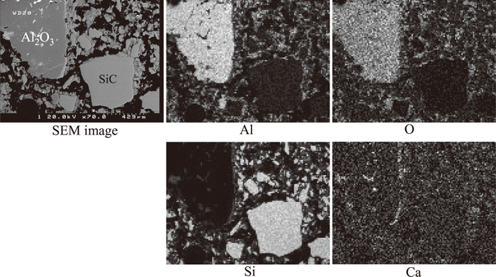
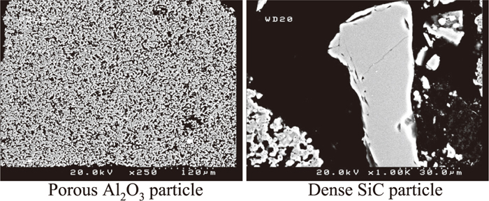
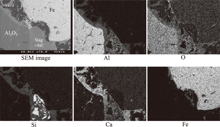
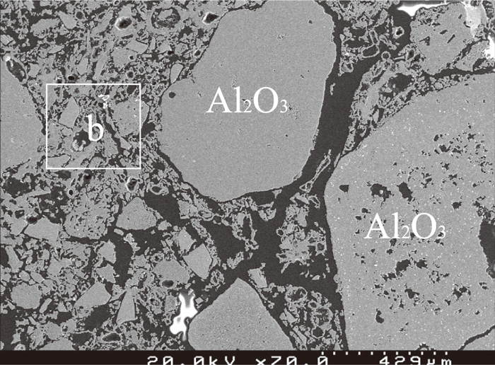
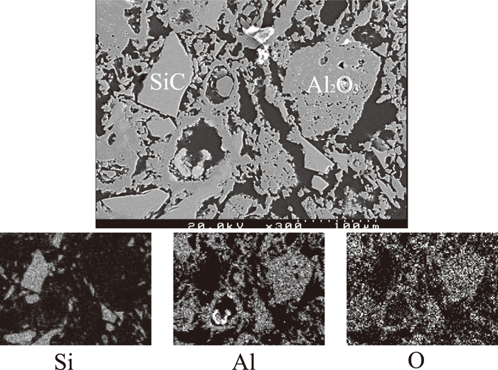
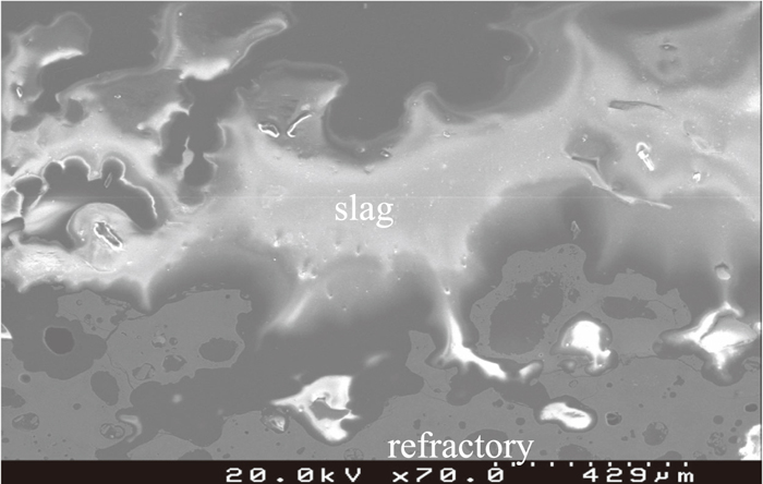
The element distribution of the sample was mapped using SEM-EDS. As shown in Fig. 2 calcium originally present in the slag was detected in the bulk of the used refractory samples especially along the surface and cracks of large porous alumina aggregates, and the pores between small dense particles. The SEM images of porous alumina aggregates and dense SiC particles are illustrated in Fig. 3. This is a good indication that the slag but not the metal penetrated deeply into the refractory lining during service. This is supported by the observation near the interface of the refractory, slag and metal as shown in Fig. 4. The slag wets the refractory well with some distributed in the bulk refractory. Slag component calcium is found only outside but not inside the dense fine SiC particles. Metal iron is present on the top of the slag layer implying that the refractory degradation is caused mostly by the molten slag rather than by the metal.
3.2. High Temperature Experimental Results
A sample of each mix listed in Table 1 was heated up to 1823 K and soaked for 7200 s to conduct the high temperature experiment. The main in-situ reactions in the standard refractory mix A proceed according to Eqs.(1) and (2).
|
Si
O
2
(
s
)
+C(
s
)
→SiO(
g
)
or SiC(
s
)
+CO(
g
)
or C
O
2
(
g
)
| (1) |
|
Si
O
2
(
s
)
+A
l
2
O
3
(
s
)
→3A
l
2
O
3
⋅2Si
O
2
(
s
)
| (2) |
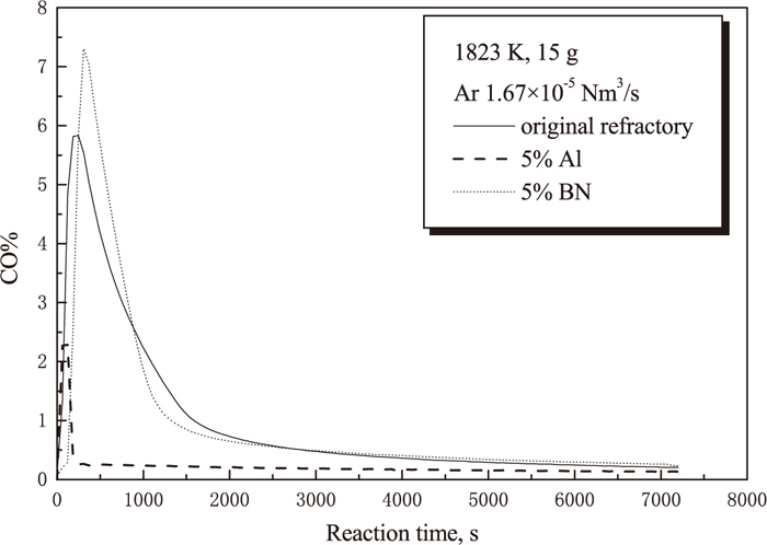
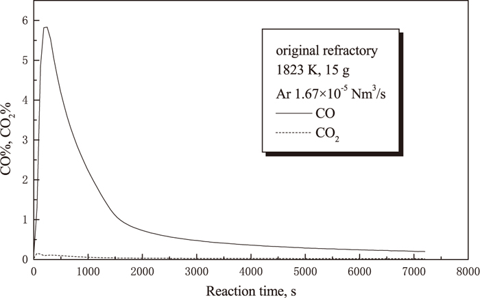
The amount of CO and CO2 released represents the carbon loss of the sample. The CO and CO2 contents in off-gas were monitored using an IR analyzer. Figure 5 shows the experimental results for the standard refractory mix A. CO gas content is much higher than that of CO2, therefore only CO gas content is illustrated in the following graphs. CO gas content increases very sharply to the maximum level of around 5.8% in no more than 600 s, and then decreases quickly to a very low value of about 1% followed by a much more gradual decay, which suggests that the in-situ reaction proceeded dominantly in the first 1500 s. Figure 6 shows the comparison of the CO gas content between the standard refractory mix A, the standard refractory mix A with 5% BN addition and the standard refractory mix A with 5% Al addition. It is clear from this graph that the amount of CO originated from the in-situ reaction is significantly suppressed by the addition of aluminium, whereas the addition of BN slightly encourages CO gas production compared to the standard refractory mix A.
The carbon removal ratio, α, is expressed by the fraction of removed carbon from a refractory sample into the gas phase (CO and CO2) to the initial carbon content in the sample as expressed by Eq. (3).
|
α=(
n
co
+
n
c
o
2
)
/
N
c
| (3) |
where, α is the fraction of carbon removed at time t, nco and nco2 are moles of CO and CO2 removed from gas phase until time t, respectively. Nc is the initial mole of carbon in the sample.
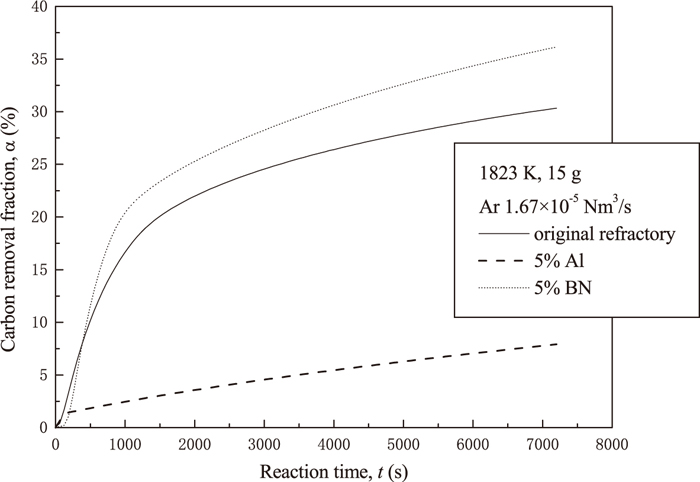
The changes of α value with reaction time for various samples are graphed in Fig. 7. The sample with 5% BN addition lost more carbon than the standard sample. However, in the case of 5% Al addition, only a small amount of CO and CO2 gas could be detected in the initial 200 s, and then almost no gas came out from the sample. This indicates that Al addition suppresses gas generation and consequently reduces the carbon removal from the refractory sample efficiently.
After experimentation, the sample with 5% BN addition fragmented into very small pieces mixing with the slag thoroughly. The standard refractory sample and the sample with 5% Al addition maintained the block shape as per before experiment. The sample with 5% Al addition after experiment was analyzed further using SEM-EDS to obtain data on slag penetration. The three-phase (refractory, slag and metal) interface image is shown in Fig. 8. Most of the slag was on the refractory surface and only a small amount of slag was distributed in the pores near the refractory surface. Figure 9 is the image of the bulk refractory. Similar to that of the used refractory from the Siphon Box, the sample is composed of large, porous alumina aggregates and clusters of small particles made up of tiny porous alumina and dense SiC particles. Figure 10 is the enlarged image of the “b” zone in Fig. 9 to show the details of the clusters of small particles. No slag component, such as calcium, was detected in this sample, which implies that slag penetration has been inhibited by Al addition.
4. Discussions
As concluded in the previous paper,15) in an inert argon atmosphere the carbon oxidation by the atmosphere is negligible and that there are two main in-situ reactions in this Al2O3–SiO2–SiC–C refractory mix as expressed in Eqs. (1) and (2).
BN addition does not have much effect on the in-situ reactions of the refractory mix according to the thermodynamic calculation. The melting point of BN is very high and it is a solid at the present experimental temperature. However, BN decomposes into N2 and B2O3 in the presence of oxides (SiO2 in the current case) from relatively low temperatures. The evolved gas makes the sample more porous fragmenting it into small pieces.
In the case of Al addition, Al is favored to reduce silica according to Eq. (4) as Al has a very strong oxygen affinity when compared to carbon.
|
4Al(
l
)
+3Si
O
2
(
s
)
=2A
l
2
O
3
(
s
)
+3Si(
l
)
Δ
G
0
=-653.21+0.126T kJ/mol
| (4) 16) |
The product, Si, of reaction (4) becomes SiC further due to its reaction with carbon in the sample as indicated by Eq. (5).
|
Si(
l
)
+C(
s
)
=SiC(
s
)
Δ
G
0
= -122.59+0.037T kJ/mol
| (5) 16) |
The overall reaction proceeded in the sample can be expressed as Eq. (6) by combining Reactions (4) and (5).
|
4Al(
l
)
+3Si
O
2
(
s
)
+3C(
s
)
=2A
l
2
O
3
(
s
)
+3SiC(
s
)
Δ
G
0
=-1 020.98+0.237T J/mol
| (6) 16) |
Clearly there are no CO and CO2 gas generated and hence no carbon loss from the sample in the case that enough aluminium is added.
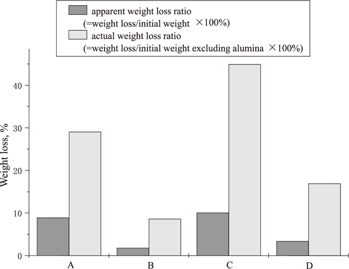
Figure 11 represents the mass loss of mixes B, C and D in which one of the standard refractory components, SiO2, SiC or C, was removed to show the influence of each component on gas formation. The mass loss of the sample without silica is the least while that of the sample without SiC is the most. There is only an insignificant reaction between silica and SiC and therefore the weight loss of the sample without carbon is minute.
|
2Si
O
2
(
l
)
+SiC(
s
)
=3SiO(
g
)
+CO(
g
)
Δ
G
0
=1 718.2-0.722T kJ/mol
| (7) 16) |
All of these results strongly support that the weight loss of the current standard refractory mix is mainly due to the reduction of silica by carbon. When 5% Al was added to the sample, Reaction (4) proceeded. Since Al was in slight excess compared to silica (7.3%), all of the silica was consumed by aluminium. Hence only alumina, SiC and carbon could be detected in the sample after high temperature experiments and almost no carbon loss was measured.
Slag does not wet carbon so the presence of free carbon reinforces the resistance of refractory against slag penetration. SiC is believed by some researchers to confer superior slag resistance. In this study, as indicated by the results of the carbon removal ratio (Fig. 7), aluminium addition hindered the carbon removal from the refractory mix whereas BN slightly enhanced the carbon releasing process so that the carbon content in the refractory mix with aluminium addition is much higher whereas the carbon content of the mix with BN addition is lower than that of the standard mix. Moreover, aluminium helped generating more SiC. As a result, the mix with 5% aluminium addition shows the strongest resistance against slag penetration among all the mixes investigated in the present study. This is consistent with the results obtained by C. F. Chan et al.12) that the carbon content of Al2O3–SiO2–SiC–C refractory powers the resistance to CaO–MgO–Al2O3–SiO2 slag penetration.
5. Conclusions
Used refractory samples after intense industrial service in the Siphon Box of a cupola furnace and laboratory samples after interaction with slag at high temperature (1823 K) in Ar atmosphere were analyzed using X-ray and SEM-EDS. 5% Aluminum and 5% BN were each added to the standard refractory mix to improve its slag penetration resistance. During high temperature experiments, CO and CO2 contents in off-gas were monitored to evaluate the influence of gas evolution from the samples on the slag corrosion resistance of the refractory materials. The following results were obtained.
(1) In Siphon Box of a cupola furnace, the refractory was directly covered by slag phase and iron metal was found on the slag. This implies that the slag corrosion plays a more significant role in the refractory deterioration process compared to molten iron.
(2) Corrosion resistance of the refractory materials against slag was largely dependent on the amount of released CO and CO2 gases originated from the in-situ reactions of the refractory samples. More gas evolution, equivalent to more carbon loss of the sample leads to poor refractory performance against slag attack since carbon is the most effective component stopping slag penetration.
(3) BN addition deteriorated refractory performance against slag penetration because more gas was evolved. Consequently more pores were generated and less carbon was left in the sample. As a result, the refractory fragmented and the slag could penetrate into the bulk of the refractory with ease.
(4) In the case of 5% Al addition, only very limited amount of CO and CO2 gases were released compared to the standard sample because silica favorably reacted with Al, rather than carbon, due to the strong oxygen affinity of aluminum to form Al2O3 and SiC at a price of a minute loss of free carbon in the sample. Both SiC and C are strongly resistant against slag penetration. Therefore the slag phase was only on the surface of this refractory sample and no slag component could be found in the bulk of the materials.
References
- 1) K. Sasai and Y. Mizukami: ISIJ Int., 35 (1995), 26.
- 2) A. J. Brown and J. White: Met. Mater. (Inst. Met.), 2 (1986), 632.
- 3) Y. Sakano and H. Takahashi: Bull. Am. Ceram. Soc., 67 (1988), 1164.
- 4) C. F. Cooper: Refract. J., 55 (1980), 11.
- 5) C. Taffin and J. Poirier: Interceram., 43 (1994), 354.
- 6) P. Brant, W. A. Lima and C. A. Groenner: Proc. of ’93 Unitecr, ALAFAR, Sao Paulo, Brazil, (1993), 462.
- 7) N. G. Lubaba, B. Rand and N. H. Brett: Br. Ceram. Trans. J., 88 (1989), 54.
- 8) S. Hayashi, S. Takanaga, H. Takahashi and A. Watanabe: Taikabutsu Overseas, 11 (1991), 12.
- 9) S. Hanagiri, T. Harada and S. Fujihara: Taikabutsu Overseas, 13 (1993), 20.
- 10) T. Kawakami, K. Aratani and S. Hasegawa: Taikabutsu Overseas, 8 (1988), 18.
- 11) J. A. Wu and H. Y. Yang: Bull. Am. Ceram. Soc., 62 (1983), 793.
- 12) C. F. Chan, B. B. Argent and W. E. Lee: J. Am. Ceram. Soc., 81 (1998), 3177.
- 13) C. F. Chan, B. B. Argent and W. E. Lee: Calphad, 27 (2003), 115.
- 14) A. P. Luz, M. M. Miglioli, T. M. Souza, S. Hashimoto, S. Zhang and V. C. Pandolfelli: Ceram. Int., 38 (2012), 3791.
- 15) L. Hong and V. Sahajwalla: ISIJ Int., 44 (2004), 785.
- 16) E. T. Turkdogan: Physical Chemistry of High Temperature Technology, Academic Press, New York, (1980), 5.