Abstract
The effect of austenite grain size on martensitic transformation, particularly with regard to martensite structure, Ms/Mf temperatures, and mechanical properties was investigated in 0.1C–5Mn martensitic steel. Utilizing a newly developed experimental technique that makes it possible to examine phase transformation behavior and conduct tensile testing with the same specimen, we examined these relationships and obtained the following results. Ms temperature decreases as much as 40 K with a decrease in austenite grain size from 254 to 30 μm. Regarding martensite structure, the packet size and the block length decrease, while the lath width does not change, with the refinement of austenite grain size by about one tenth. Grain boundary density, especially high-angle grain boundary density, increases with decreasing austenite grain size. Tensile strength slightly increases though austenite grain size decreases about one tenth. However, reduction in area significantly improves particularly at refined grain sizes of 30 μm. True stress - true strain curves obtained up to fracture elucidates that the austenite refinement substantially improves true fracture strength and greatly increases true fracture strain of martensite, potentially invalidating the conventional concept of a trade-off between strength and ductility. Low C–5Mn martensitic steel produced from fine austenite shows a great possibility having an excellent total balance of strength, ductility and toughness.
1. Introduction
It is interesting and important to understand how austenite grain size refinement affects martensitic transformation, particularly with regard to Ms (start of martensitic transformation) temperature, microstructural morphology (packet, block, lath), and overall mechanical properties. Sastri et al.1) and Maki et al.2) have pointed out that such refinement acts to lower the Ms temperature. In their study, Sastri et al. investigated Fe–0.33C–3.26Ni–0.85Cr–0.09Mo–0.23Si–0.57Mn–0.007S–0.005P steel and found that Ms temperature decreases from 304°C to 277°C when the austenitizing temperature changes from 1200°C to 800°C.
With regard to microstructures, Takaki et al.3) and Tomimura et al.4) have shown that in a 16Cr–10Ni steel, martensitic transformation is hindered at austenite grain sizes finer than some critical size. Indeed, these researchers show that such steel does not undergo martensitic transformation when its austenite grain size is less than 1 μm.
As for mechanical properties, we have yet to see a definitive report on the relationship between austenite grain size and martensitic transformation. This said, fine martensite is obtained under ausforming (that is, obtaining martensite through transformation from work-hardened austenite), and it is generally believed that fine martensite improves Charpy impact properties but does not have much effect on tensile strength.
In the case of low carbon steels, austenite grain refinement promotes the formation of polygonal ferrite at austenite grain boundaries. In other words, the propensity to form martensite can be decreased by grain refinement. As a consequence, because grain refinement makes it more difficult to obtain a purely martensite structure, researchers cannot easily examine relationships among austenite grain size, Ms temperature, microstructural morphology (packet, block, lath), and mechanical properties.
Most studies to date concern steels with large Ni additions to increase hardenability. Often, the Mf (finish of martensitic transformation) temperature of such steels is lower than room temperature, thereby necessitating a subzero heat treatment (i.e., cooling to well below room temperature) to obtain a purely martensite structure. Note too that large additions of Ni greatly change the mechanical properties of low C steels.
A determination of Ms temperature requires a simultaneous measurement of both temperature and volumetric expansion. This is not easy to do under either (1) water quenching or (2) subzero heat treatment. Largely because of such experimental difficulties, it is still not well understood how austenite grain refinement affects martensitic transformation, Ms temperature, microstructural morphology, and mechanical properties.
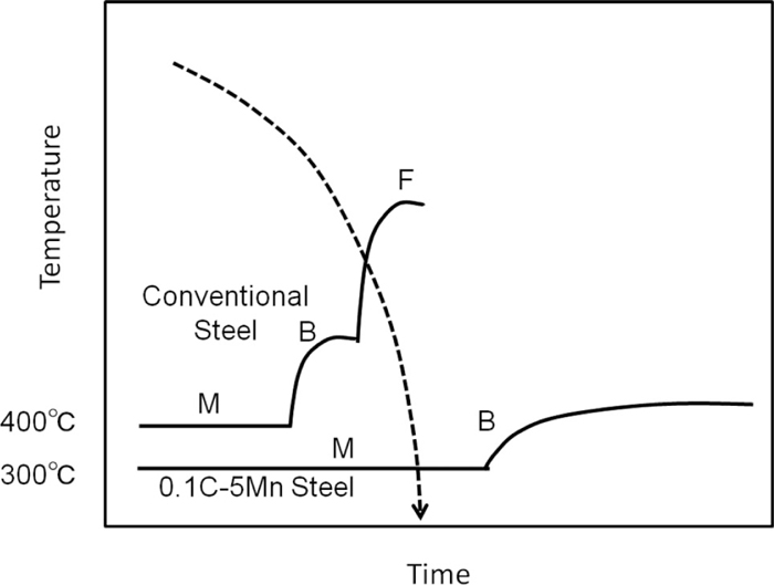
We have recently been examining 0.1C–5Mn steel, reporting5,6) that this material offers excellent mechanical properties in comparison to common martensitic steels (Fe–0.1C–1.5Mn–0.3Si steel and Fe–0.25C–1.5Mn–0.3Si steel; Fig. 1).7,8) The most notable feature of this steel is its 5% Mn content, which increases hardenability and enables 100% martensitic transformation even under air cooling.7,8) In contrast, with most conventional steels, water quenching is required to produce a fully martensitic structure (slow cooling generally produces bainitic structures). This concept is schematically illustrated in Fig. 2. Also, as the Ms and Mf temperature range of 0.1C–5Mn steels is 350 to 250°C, subzero heat treatment is not needed to bring about a full transformation. This facilitates the dilatometric measurement of Ms and Mf temperatures.

Thus, with 0.1C–5Mn steel, it is possible to obtain a fully (100%) martensitic structure even from fine austenitic structures. This allows us to easily examine the mechanical properties of martensitic structures transformed from prior austenite with a wide range of grain sizes. Here, we note that austenite grain size refinement potentially offers much control over the morphology of resulting martensitic structures; e.g., four packets per austenite grain, one packet per austenite grain, or one block per one austenite grain (single variant transformation), as shown schematically in Fig. 3.

As-quenched martensite is known to be generally low in ductility and toughness. As has been pointed out elsewhere,9,10) if the austenite grain size is sufficiently fine, the Ms temperature should be lower than it would be otherwise, leading to a refinement in the resulting martensite structures. Here we take a structural point of view, examining the effect of austenite grain size on Ms temperatures, martensite structure, and mechanical properties (tensile strength, elongation, and toughness).
In this study, we mainly focus on precision heat treatment in conjunction with dilatometric measurement to obtain austenite with various grain sizes and to determine cooling rates accurately. This allows us to precisely examine relationships among various austenite grain sizes, Ms and Mf temperatures, and resulting martensite structures. We also attempt to obtain mechanical properties directly from dilatometric specimens and, for this purpose, have developed a dilatometric measurement system that is capable of using large tensile testing specimens. Furthermore, to elucidate the true underlying mechanical properties, such as the true strain up to the fracture, it is preferable to use true stress-true strain curves, and here we applied our newly-developed image analysis tensile test methods.11)
Through experimental trials, this study attempts to clarify the effect of austenite grain size on the strength, ductility, and toughness of 0.1C–5Mn martensitic steel.
2. Experimental
Ingots were produced from steel refined in a vacuum induction furnace to a composition shown in Table 1. They were then hot-forged at 1200°C to rectangular sections followed by air cooling. Specimens of 30 mm in length and 3 mm in diameter were machined from these sections and subsequently soaked at different austenitizing temperatures, where they were held for 10 min followed by cooling at a cooling rate of 1 K/s. A temperature-thermal expansion curve was obtained for each specimen by means of a dilatometer (Fuji Electric Formastor FII).
Table 1. Chemical composition of the steel used in this study (wt.%).
| C | Si | Mn | P | Total Al | O ppm | N ppm |
|---|
| 0.1 | 1.96 | 5.02 | 0.000 | 0.001 | 18 | 5 |
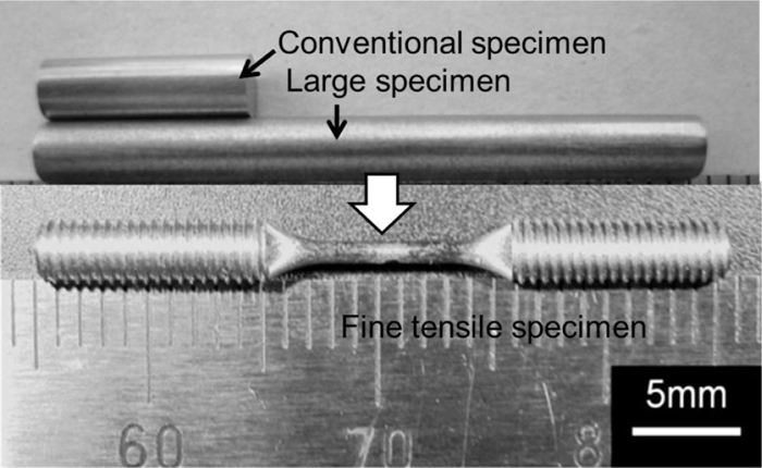
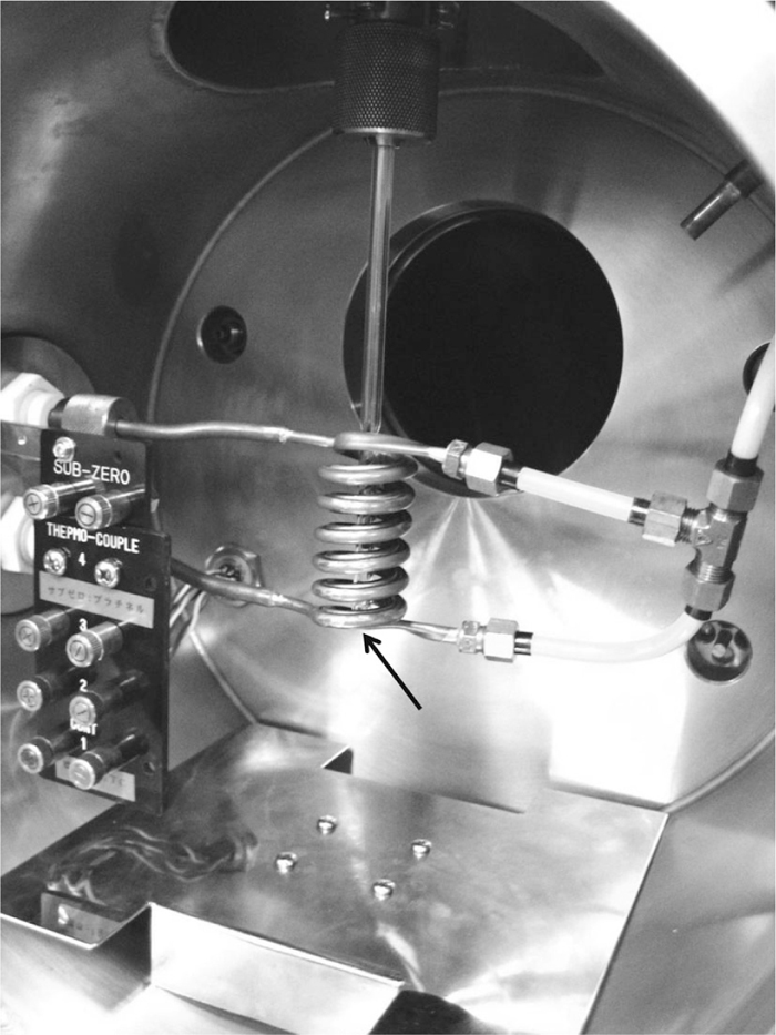
Utilized to heat the specimens was a newly developed induction coil (Fig. 4) that is three times longer than a conventional induction coil. This allowed us to use longer specimens from which we could subsequently prepare fine tensile specimens. To check the temperature distribution along such specimens, three thermocouples were spot-welded to each to facilitate temperature measurement during heat treatment. Change in temperature at three different points on a typical long specimen is shown in Fig. 5, where the indications Top, Center and Bottom correspond to locations on the specimen to which the thermocouples were attached.
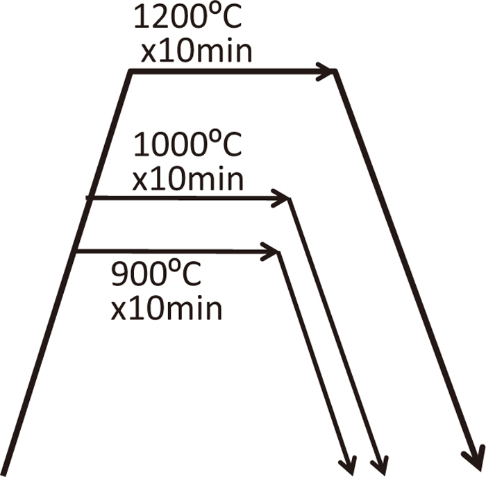
The heat treatment regime utilized in this study is shown schematically in Fig. 6. Specimens were soaked at 900, 1000, or 1200°C for 10 min, respectively, followed by cooling at a rate of 1K/s. They were machined to round-shaped, fine tensile test specimens of ϕ1 × 5 mm gauge length (Fig. 7). Tensile tests were conducted on those specimens at room temperature under a strain rate of 0.5 mm/min.
Also prepared were Charpy impact specimens, which were also soaked at 900, 1000, or 1200°C for 30 min followed by air-cooling.
The microstructures of the specimens were examined by scanning electron microscopy and electron backscatter diffraction (EBSD). The EBSD examination consisted of grain boundary mapping at an acceleration voltage of 15 kV and step size of 0.6 μm over a 280 × 500 μm area.
3. Results and Discussions
3.1. Relationship between Austenite Grain Size and Ms Temperature
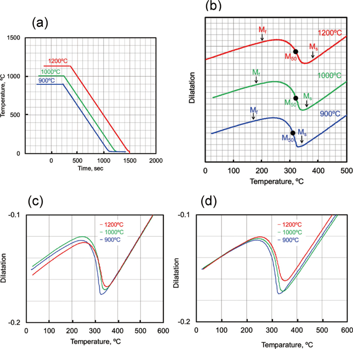
Figure 8(a) shows change in temperature with time during cooling under dilatometric testing. We note that cooling rate (1 K/s) is stable down to room temperature, even with a martensitic transformation starting around 340°C (the transformation is exothermic, making it somewhat difficult to maintain a constant cooling rate through it12)). Figures 8(b), 8(c), and 8(d) show dilatation curves as a function of temperature under three different conditions (holding at 1200°C, 1000°C, and 900°C, respectively), where (b) shows curves indicating Ms, M50%, and Mf, (c) shows curves set together at Ms, and (d) shows curves set together at Mf. We discuss the relationship between austenite grain size and Ms, M50%, and Mf temperatures later. Apparent among these three curves is some difference in absolute dilatation value. This is attributed to two sources of error: (1) hysteresis in the operation transducer, and (2) slight non-vertical alignments (i.e., tilting) of the specimens.
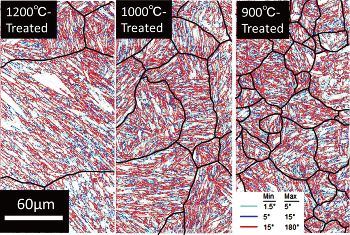
In the case of the transformation from austenite to martensite, the crystallographic structure of austenite and that of martensite satisfy the K-S relationship, under which 24 variants can be produced from one austenite grain. In this study, by focusing on adjacent blocks, prior austenite grains were determined by identifying identical variants among the 24 variants. The martensite microstructures of austenitized specimens at 1200°C, 1000°C, and 900°C are presented in reference to EBSD orientation maps, as shown in Fig. 9. Prior austenite grain boundaries were represented here by black lines. All blocks inside each grain boundary have a K-S relationship with each other. Average austenite grain sizes are determined by the linear intercept method to be 245 μm, 84 μm, and 30 μm, respectively.

Grain boundary maps of the three different martensitic structures are shown in Fig. 10. In this figure, colored lines are used to represent three groups of different misorientations: pale blue for 1.5° < θ < 5°, blue for 5° < θ < 15°, and red for 15° < θ, where θ is the misorientation angle. From Figs. 9 and 10, when austenite grain size is reduced to 30 μm, the observed martensite is found to be conventional in morphology, consisting of packets and blocks. Bright field images from transmission electron micrography are shown in Fig. 11 for the three different martensite structures. Packet sizes are schematically shown in Figs. 11(a), 11(b) and 11(c). Packet size clearly becomes smaller with decreasing austenite grain size.
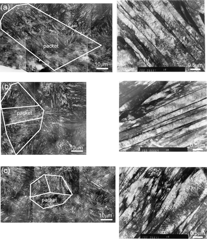
From this figure it can be seen that as the austenite grain size decreases, the packet size and the block length decrease, while the lath width changes only slightly, suggesting that the HV value for each specimen is almost the same. This result is in good agreement with the EBSD observation in Fig. 10. This almost agrees with the result by Morito et al.9) Since block length generally corresponds to the width of packet, block length becomes smaller. Block corresponds to the same color region in austenite grain in Fig. 9. The width of block, thus, seems not change so much among the three kinds of microstructures from both data of Figs. 9 and 10. Lath does not seem to change in its width among the three kinds of microstructures as shown in Fig. 11. As for block width, further detailed variant analysis needs to be conducted.
Figure 12 shows the relationship between austenite grain size and Ms, Mf, and M50% temperatures. In the figure, HV values are indicated together with change in Ms, Mf, and M50% temperatures. We note that as austenite grain size decreases, Ms and Mf temperatures decrease gradually (or, in the case of a 30 μm austenite grain size, they decrease significantly).The M50% temperature, on the other hand, stays fairly constant. The reason that the HV does not change much with decreasing austenite grain size seems to be related to the observation that the M50% temperature does not change much either (an assumption here is that M50% is proportional to dislocation density). Bhadeshia et al. have also pointed out that Ms temperature changes with austenite grain size and it is difficult to obtain accurate Ms temperature.12) They explained that the volume fraction of martensite formed in an early stage of transformation is proportional to the cube of austenite grain size. Thus, when the austenite grain size is large, the fraction of transformation needed to detect Ms is reached at a smaller degree of undercooling.12) The reason why Ms and Mf points decrease as the austenite grain size is decreased can be explained as follows based on the reference3): When the austenite grain size is large, multivariant blocks form to minimize the total volume expansion accompanied with the martensitic transformation. As a result, the elastic strain energy generated with the transformation becomes small. However, the variant selection is restricted with decreasing the austenite grain size, and therefore, the relaxation of volume expansion becomes insufficient and the elastic strain energy becomes large. The compensation of this elastic strain energy by chemical free energy change is necessary for the nucleation of martensite, and therefore, super-cooling is needed. Thus, with decreasing the austenite grain size, more super-cooling is required.

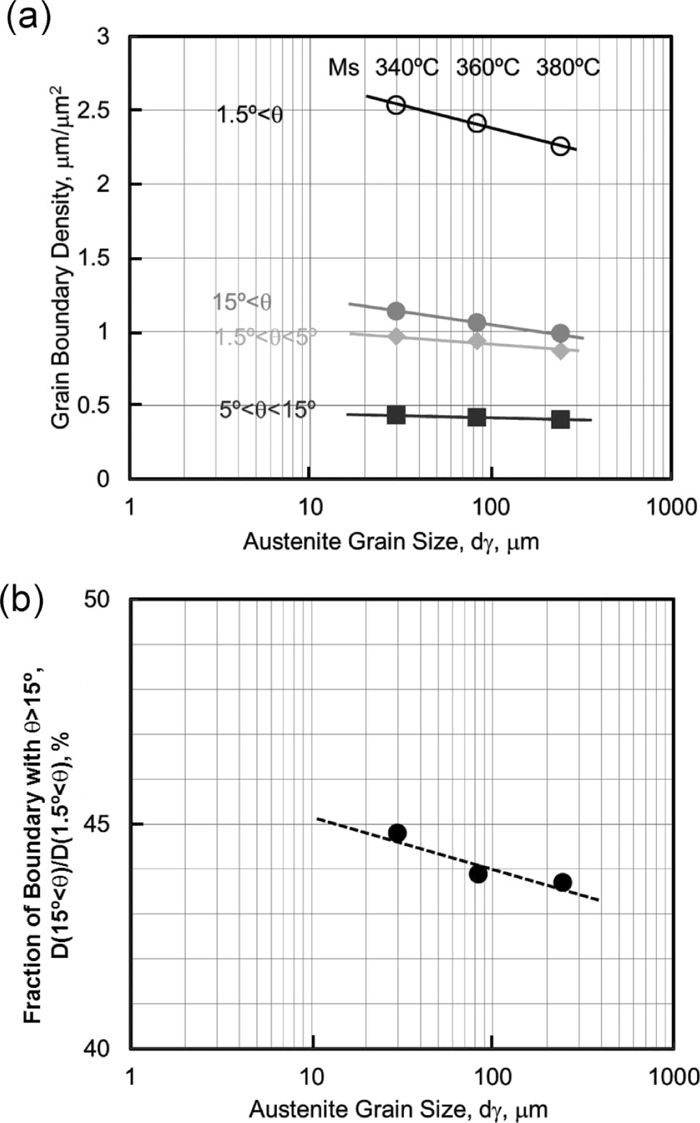
Next, we examined the change in boundary density with austenite grain size. Boundary density is defined as total boundary length divided by measured area. In Fig. 13(a), three classifications of grain boundary densities are represented as a function of austenite grain size: 1.5° < θ < 5°; 5° < θ < 15°; and 15° < θ. It is interesting to note that as austenite grain sizes decrease, densities increase for all three classifications. The fraction of high-angle (15° < θ) grain boundaries is also found to increase with decreasing austenite grain size, as shown in Fig. 13(b). The graph of 1.5° < θ corresponds to the denomination of the graph of D (15° < θ)/D(1.5° < θ) in Fig. 13(b). It is interesting that smaller austenite grains assist in the generation of high angle boundaries.
3.2. Mechanical Properties
3.2.1. Tensile Properties
Nominal stress-nominal strain curves for three martensite structures produced with different austenite size are shown in Fig. 14. These three martensite structures have 1400 MPa-class high strength. In detail, the microstructure with smaller austenite grain size has slightly higher tensile strength. However, total elongation is somewhat different. Total elongation increases with decreasing austenite grain size. A difference in reduction in area among the three kinds of specimens is also apparent upon comparing the edge of fractured specimens (Fig. 15). When the austenite size is 84 μm or larger, the reduction in area is almost the same. However, when the austenite grain size is 30 μm, the reduction in area drastically increases as shown in Fig. 15.
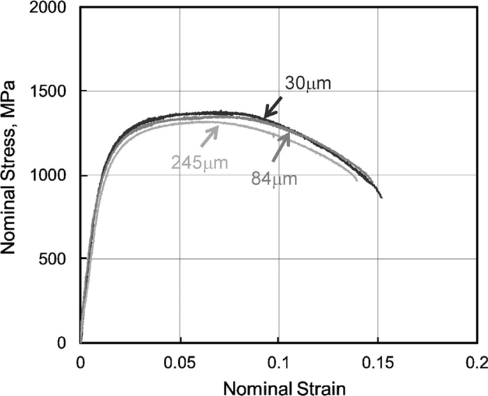

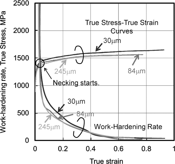
Figure 16 shows true stress-true strain and work-hardening rate curves for the three different microstructures observed by image analysis tensile testing,11) which can reveal true stress-true strain behavior up to fracture (conventionally, this curve is limited up to the start of necking, as has been reported by Wang et al.10)). Our results show that the cross point between the true stress and the work-hardening rate (true tensile strength) increases with decreasing austenite grain size. The end of each true stress-true strain curve means true fracture stress and true fracture strain. Also, austenite grain size refinement substantially improves true fracture stress and greatly increases true fracture strain, potentially invalidating the conventional concept of a trade-off between strength and ductility. The fact that the tensile strength does not change so much among the three microstructures is in good agreement with the TEM data of Fig. 11, where lath width stays essentially constant with decreasing austenite grain size while packet size and block length decrease with decreasing austenite grain size. In this case, however, this difference in ductility (fracture strain) cannot be explained in terms of grain boundary density because ductility generally decreases with an increase in grain boundary density. Instead, the difference here is believed to be related to a refinement of packet and block sizes.
Well-known nucleation sites for void formation are inclusions, second phases, and boundaries. Since there are few inclusions or second phases (cementite, etc.) in the steels used in this study, only grain boundaries are thought to offer a significant number of nucleation sites for void formation. Grain boundaries can be attributed to prior austenite boundaries, packet boundaries, and block boundaries.
Dislocations introduced by deformation accumulate at packet boundaries. One possible explanation for the increase in local ductility (reduction in area) with decreasing austenite grain size is as follows. Accumulated dislocations at packet boundaries lead to void formation. According to the Hall-Petch theory, at an equal quantity of dislocations, dislocations accumulate less at the boundaries of smaller grains. Therefore, a refinement of packet size increases the amount of deformation necessary for void formation. This would help to explain why a decrease in packet size led to an increase in a reduction in area and local elongation in this study.
Regarding void growth, McClintock13) has indicated that in the case of ductile fracture, a ductile crack propagates due to an increase in tri-axial stress, which enlarges a void at the propagating crack tip where it coalesces, leading to further crack propagation. However, when the size of the grain containing the void is small enough, the stress required for the void growth increases, thereby retarding crack propagation, which fact expresses itself as an enhancement of a reduction in area and local elongation.
3.2.2. Charpy Impact Properties
Specimens machined to dimensions of 17 × 17 × 100 mm were heat-treated in a manner similar to the Formastor treatment but with a different annealing time (30 min instead of 10 min) and air cooling instead of controlled cooling at a rate of 1 K/s. This is because the large volume of the specimens necessitates a longer soaking period. The austenite grain size of each Charpy impact specimen was examined and confirmed to be of the same level as that of corresponding smaller specimens.
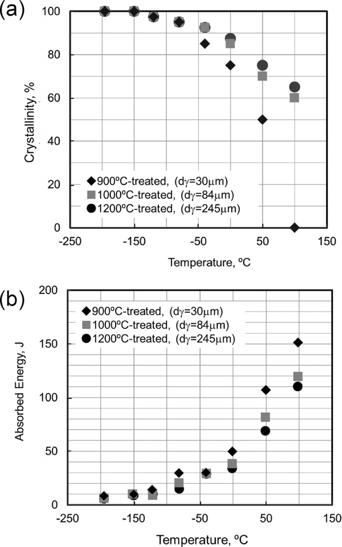
Crystallinity and absorption energy in Charpy impact testing are plotted as a function of test temperature in Figs. 17(a) and 17(b), respectively.
The change in crystallinity does not differ much among austenite grain sizes down to roughly 80 μm. When the austenite grain size is 30 μm, however, crystallinity decreases drastically, as shown in Fig. 17(a). Absorption energy increases when the austenite grain size is 30 μm, in comparison with the austenite grain sizes of 80 μm or larger, as shown in Fig. 17(b).
According to Yaffee as described in Morris’s paper,14) when the cleavage fracture stress is higher than the flow stress, the material fractures in a ductile manner. Conversely, when the cleavage fracture stress is lower than the flow stress, the material fractures in a brittle manner.
According to the Griffith theory,15) cleavage fracture stress depends on crack size and fracture surface energy, as shown in the following equation.
Here,
σF is cleavage fracture stress,
γ is cleavage fracture surface energy, E is Young’s modulus, and r is crack size.
In a previous study, we demonstrated that effective grain size, corresponding to crack size in the Griffith theory, has a dramatic effect on fracture stress in terms of dEFF–1/2, as shown in Fig. 18 from references.16,17) These fracture stress values in Fig. 18 are determined as follows. When we assume that fracture stress is independent of temperature and becomes equal to the flow stress at the ductile-brittle transition temperature (DBTT), we can estimate the fracture stress by taking yield stress to be the flow stress at the DBTT.

The surface energy of cleavage fracture in the martensite structure is the highest in comparison to ferrite and pearlite structures, as shown in Fig. 18. In the figure, two dotted lines are shown as a reference; plastic fracture surface energy20) and fracture surface energy of ferrite.21) It has earlier been confirmed that grain refinement of prior austenite increases upper shelf energy and decreases DBTT. Similar experimental results (in which it is shown that grain refinement of tempered martensite decreases DBTT) have been demonstrated for quenched and tempered specimens, as can be seen in Refs. 18) and 19). However, they do not clearly elucidate any mechanism under which effective grain size would exert some control over impact properties. Our results indicate the potential of grain refinement of prior austenite for the simultaneous and total balancing of properties relating to martensite structure, including strength, ductility, and toughness.
From an examination of Charpy fracture surfaces, the effective grain size for specimens with an austenite grain size of 84 μm and 30 μm has been estimated to be about 30 μm and 10 μm, respectively. Those two data sets are superimposed on Fig. 18, from which we note that the specimen with a 30 μm austenite grain size has a cleavage fracture stress of about 1600 MPa, while that with an 84 μm austenite grain size has a fracture stress of about 920 MPa.
When the austenite grain size is 30 μm, the flow stress is lower than the cleavage fracture stress (1600 MPa). On the other hand, in the case of the 84 μm specimen, the flow stress is higher than the cleavage fracture stress (920 MPa). The crystallinity of the 30 μm specimen at room temperature is much lower than that of the 84 μm specimen. As a result, the absorption energy of the 30 μm specimen is higher than that of the 84 μm specimen.
If the steel has a low carbon content, interaction between carbon atoms and dislocations in the martensite matrix is slight, and so flow stress, or yield stress, does not become particularly high. On the other hand, when austenite grain size is reduced, fracture stress becomes higher. Because of these factors, martensite formed from small austenite grains tends to have a higher fracture stress and a higher true fracture strain, resulting in no early fracture. In addition, since the matrix contains carbon in solution, it has a high strength. In other words, to obtain steel with high strength, high ductility, and high toughness, it is beneficial for the matrix to consist of low-carbon, martensite produced from austenite of the smallest possible grain size. We believe this to be one principle for innovative steel creation and consider 0.1C–5Mn to be a good composition with which to manifest this principle.
4. Conclusions
In this study, 0.1C–5Mn steel is used to examine the relationship between prior austenite grain size, microstructure, transformation behavior and the mechanical properties of resulting martensite structures with a precise dilatation method and newly developed tensile test method. The following conclusions are obtained.
(1) In the 0.1C–5Mn steel, Ms and Mf are found to decrease with decreasing the austenite grain size; with austenite grain size from 245 μm to 30 μm, Ms from 380°C to 340°C, and Mf from 200°C to 170°C.
(2) With the refinement of austenite grain size, to about one tenth, the packet size and the block length decrease, while the lath width does not change.
(3) Grain boundary density, especially high-angle grain boundary density, increases with decreasing austenite grain size.
(4) In spite of austenite refinement by about one tenth, the tensile strength increases very slightly, but the reduction in area increases significantly.
(5) True stress - true strain curves obtained up to fracture elucidates that the austenite refinement substantially improves true fracture strength and greatly increases true fracture strain of martensite, potentially invalidating the conventional concept of a trade-off between strength and ductility.
(6) The crystallinity decreases drastically when the austenite grain size becomes smaller down to 30 μm.
(7) Low C–5Mn martensitic steel produced from fine austenite has an excellent total balance of strength, ductility and toughness.
Acknowledgements
This study was supported by the Japan Science and Technology Agency under “Heterogeneous Structure Control,” a collaborative research initiative based on industrial demand.
The authors gratefully acknowledge experimental support from Yasuji Masuda, Masayuki Komatsu, and Eijiro Muramatsu for fabricating a special gliding machine and machining fine tensile specimens. We also would like to thank Satoshi Iwasaki, Koji Nakazato, Takaaki Hibaru, Syuji Kuroda, Yasushi Taniuchi, Sadao Hiraide, Noboru Sakurai, and Goro Arakane for their help with material preparation, and Elena Bulgarevich and Aiko Takanabe for their assistance with structural analysis.
References
- 1) A. S. Sastri and D. R. F. West: J. Iron Steel Inst., 203 (1965), 138.
- 2) T. Maki and I. Tamura: Tetsu-to-Hagané, 67 (1981), 852.
- 3) S. Takaki, K. Furunaga, J. Syarif and T. Tshuchiyama: Mater. Trans., 45 (2004), 2245.
- 4) K. Tomimura, S. Takaki, S. Tanimoto and Y. Tokunaga: ISIJ Int., 31 (1991), 721.
- 5) T. Furukawa and O. Matsumura: Netsu Shori, 37 (1997), 204.
- 6) H. Takechi: JOM, December (2008), 22.
- 7) T. Hanamura, S. Torizuka, A. Sunahara, M. Imagumbai and H. Takechi: ISIJ Int., 51 (2011), 685.
- 8) S. Torizuka and T. Hanamura: Ferrum, 17 (2012), 852.
- 9) S. Morito, H. Saito, T. Ogata, T. Furuhara and T. Maki: ISIJ Int., 45 (2005), 91.
- 10) C. Wang, M. Wang, J. Shi, W. Hui and H. Dong: J. Mater. Sci. Technol., 23 (2007), 659.
- 11) N. Murayama, S. Torizuka, T. Hanamura and M. Imagumbai: Tetsu-to-Hagané, 98 (2012), 415.
- 12) H. S. Yang and H. K. D. Bhadeshia: Scr. Mater., 60 (2009), 493.
- 13) F. A. McClintock: Fracture, An Advanced Treatise, Vol. III, ed. by H. Liebowitz, Academic Press, New York, (1971).
- 14) J. W. Morris, Jr., C. S. Lee and Z. Guo: ISIJ Int., 43 (2003), 410.
- 15) A. A. Griffith: Philos. Trans. R. Soc., A221 (1920), 163.
- 16) T. Hanamura, F. Yin and K. Nagai: ISIJ Int., 44 (2004), 610.
- 17) T. Hanamura, M. Zhao, Y. Fuxing, H. Qui and K. Nagai: Tetsu-to-Hagané, 95 (2009), 71.
- 18) T. Inoue, S. Matsuda, Y. Okamura and K. Aoki: Trans. Iron Steel Inst. Jpn., 11 (1970), 36.
- 19) H. Ohtani, K. Terasaki and T. Kunitake: Tetsu-to-Hagané, 58 (1972), 434.
- 20) T. Yokobori: Tech. Rep. Tohoku Univ., 29 (1964), 167.
- 21) A. Kelly, W. R. Tyson and A. H. Cottrell: Philos. Mag., 15 (1967), 567.