Study
Friction welding processes can replace traditional arc welding to join and repair structures.1,2) The Friction Hydro Pillar Processing (FHPP) was patented in 1992 by TWI and it is used to join and repair metallic structures.3) FHPP involves drilling a hole in the structure containing a previous discontinuity and rotating a consumable rod co-axially against it under an applied load to generate frictional heat and a continuously plasticised layer, filling the hole completely3) (Fig. 1(a)). The hole and the rod may be parallel or tapered. When using this last possibility the process may be called Friction Taper Stud Welding (FTSW).4)

FHPP is an innovative solid state technique capable of joining dissimilar materials with applications in the transportation, energy and offshore industries. It can be automated and distance operated ensuring greater reproducibility and reliability for in-situ repairs. It is also a safe, portable and fast processing alternative to traditional arc welding processes, avoiding high thermal cycles, consumables, fumes generation and able to produce a joint with superior mechanical properties.5,6,7,8) A few disadvantages that may occur in FHPP include lack of bond, incompletely filled groove, inclusions modification and microcracks due to inadequate joint geometry, material flow and welding parameters, leading to complex representative mechanical and metallurgical characterization.5,6,7) Within welding parameters, the axial force has a strong relationship with the final quality of the joint. It controls processing time and heat input,9) influencing mechanical and metallurgical properties, material deformation and the morphology of inclusions present in the steel after processing.10,11,12) Nevertheless, a subsequent inspection able to cover the repair totality is needed. Among non-destructive techniques, ultrasonic testing may be used to evaluate discontinuities like lack of metallurgical bond, inclusions and microcracks in friction welded interfaces.13,14,15,16,17,18)
The present study aim was to evaluate the influence of different axial forces in discontinuities within ASTM A36 steel repairs with FHPP. Ultrasonic inspection and micrographic techniques were applied and correlated to check this non-destructive method capacity and potential application.
For each weld, 100 × 100 × 63,5 mm plates and 3,81 mm diameter rod of ASTM A36 low carbon steel, widely used in the industry,19) having a nominal composition of Fe–0.2C–0.11Si–0.55Mn–0.0183P–0.023S (wt pct) and Fe–0.19C–0.10Si–0.54Mn–0.0199P–0.031S (wt pct) respectively in this investigation. The plates used were drilled from hot-rolled 63,5 mm slabs and the rods used in the repairs were machined from hot rolled round bars with a diameter of 38.1 mm (Fig. 1(b)). Inside the rod raw material eventually large and elongated inclusions may be present. The inclusion of MnS, originally equiaxed as cast condition, it is flattened after the hot rolling process. In round bars they appear as elongated strips around the central axis.20,21)
The process parameters used where 1000 rpm for rotation speed and axial forces of 200, 250, 300 and 350 kN. Three welds per axial force were produced totalizing 12 repairs.
The investigation was carried out with an ultrasonic transducer at the remaining upper face of the rod using an unfocused piezoelectric element with 6.35 mm crystal diameter and frequency of 10 MHz from Olympus (Panametrics Transducers UT), in pulse-echo mode (illustrated in Fig. 1(c)) and a calculated minimum discontinuity resolution of 0.29 mm. The transverse plane with the highest incidence of ultrasonic beam reflections was used for micrographic analysis. For the micrographs, the samples were etched with 3% Nital. Unities in the obtained echograms are Volts (y) and microseconds (x).
After the evaluation of all samples, three significant regions within the repairs were observed and distinguished. The nomenclature adopted for the study was: central lower region, lower curvature radius region and lateral region. Each region showed different ultrasonic signal features related to different discontinuities.
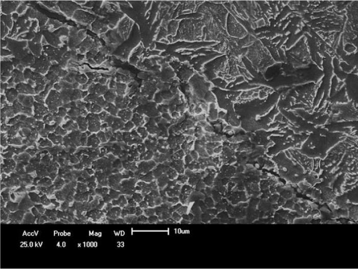
In the central lower region (arrow in Fig. 2(a)) close discontinuities may appear showing ultrasonic beam reflections characterized by successive signals (e.g. Fig. 2(c)). In these cases micrographs showed flattened clustered inclusions (e.g. Figs. 2(b) and 2(d)). Due to rotational deformation former inclusions strips acquire a helicoidal form. Inclusions morphology observed in this work and formerly studied material flow in FHPP22) shows that inner material, due to rod rotation and friction against the base material, suffers rotational deformation rather than series of shear interfaces. Inclusions flattens due to processing and post processing axial force and their orientation follows flow of material orientation, as shown in the micrographs. Intrinsic to the material they may appear independent of the axial force used.

The amount, shape, size, and distribution of these inclusions are subject to process restrictions because the sulfides can act detrimentally on the mechanical properties of the material.20)
In the lower curvature radius region (arrow in Fig. 3(a)) large discontinuities may occur showing ultrasonic beam reflections characterized by dispersed signals (e.g. Fig. 3(c)). In these cases micrographs showed discontinuities in the interface of the materials, varying from punctual to about 1 mm large interface lines contouring the flowed plasticized material characterizing lack of bond13) or incomplete diffusion (e.g. Figs. 3(b) and 3(d)). Total volume of these discontinuities generates prolonged ultrasonic signals.
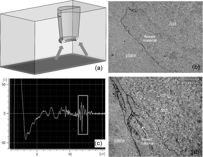
It was possible to note the effect of time and temperature in the bonding process. Repairs made with higher forces (e.g. Fig. 3(d), 350 kN axial force) incomplete bonding and larger variation in grain size between the rod and the flowed material was seen. In this condition process duration and heat input are lower,9) approximately 10,98 s and 32,75 kJ/mm respectively in Fig. 3(d)’s sample, providing higher temperature gradient. Microcracks that could be originated during the cooling process are also notable in the flowed material. Repairs made with lower forces (e.g. Fig. 3(b), 200 kN axial force) almost complete bonding and similar grain size between the rod and the flowed material was seen. In this condition process duration and heat input are higher,9) approximately 26,95 s and 83,11 kJ/mm respectively in Fig. 3(b)’s sample, providing lower temperature gradient. Interfaces between the plate and flowed material in this condition may also present lack of bond after thermal contraction of the flowed material in this region.
Lack of bond does not affect all the circumferential interface area of the lower curvature radius region, it’s a punctual discontinuity that may be originated by dragged inclusions. Located in a critical location (i.e. the bonding line) they could break under load and cause a greater defect in the repair.11) A partially bonded interface can be better observed in Fig. 4.
In the lateral region (arrow in Fig. 5(a)) discontinuities closer to the surface may appear resulting in an earlier ultrasonic beam reflection (e.g. Fig. 5(b)). In these cases micrographs show flattened inclusions oriented in the angular direction of material flow in this region (e.g. Figs. 5(c) and 5(d)).
As in any manufacturing welding method, there is an optimization of process parameters to assure the best result (defect free and optimal mechanical properties) for each material grade application. Inclusions and lack of bond found in this work could render a part or product unable to meet minimum applicable acceptance standards or specifications. A reasonable approach to evaluate the safety of the component with discontinuities under stress is fracture mechanics, providing quantitative values of material toughness and making possible projects that combine safety and economic viability.23,24)
The analysis of echograms features and micrographs allowed to locate and differentiate inner inclusions and lack of bond in the interface between the rod and plate materials in FHPP repairs. Inclusions can appear flattened, clustered or isolated, deformed and oriented in the direction of the material flow.
Lack of bond in bonding line of the rod lower curvature radius region, contouring the flowed material, may appear due to inclusions and thermal contraction. Higher processing forces increases probability to generate microcracks in theses discontinuities and produces larger variation in grain size while repairs made with lower axial force promotes bonding between the materials and reduces the difference in grain size. Lack of bond occurs randomly and punctually within the repair.
Ultrasonic testing showed potential application in Friction Hydro Pillar Processing repairs inspection covering critical regions of the repair.
Since that discontinuities were found, and that currently there are no codes and specification for FHPP repairs, more investigation with different materials, geometries and process parameters are needed to provide more data for analysis, in combination with fracture mechanics tests to evaluate the allowance of the discontinuities.
The authors would like to acknowledge the financial support from CNPq and CAPES.