Note
Heat Transfer in a Bed of Dry Iron Ore Pellets
2013 年 53 巻 4 号 p. 723-725
詳細
2013 年 53 巻 4 号 p. 723-725
Iron ore pellets are used as an intermediate product in the production of steel. Their size of approximately 10 mm diameter combines ease of handling with the ability to control air flow and heat distribution in a blast furnace. Previous studies have investigated the thermal properties of iron ore pellets over from 30 to 800°C, i.e. over a temperature range relevant for blast furnaces.1) It was found that the thermal conductivity and diffusivity decreases with increasing temperature, and that the specific heat peaks at around 680°C due to a phase transition. Heat and mass transfer of individual pellets exposed to a stream of air has been subject to computational fluid dynamics simulations.2) In earlier energy transfer measurements, the diffusivity of individual iron ore pellets was found to range between 2.9 and 3.6×10⁻⁷ m2 s–1 over a temperature range from room temperature to 680°C.3)
This study focuses on heat transfer over a temperature range commonly observed during transport of iron ore pellets. Specifically, KPBO pellets of Luossavaara Kiirunavaara Aktiebolag (LKAB) are commonly shipped shortly after production, i.e. while warm (30°C). However, some batches may have been stored outside at sub-freezing temperatures commonly observed to be as low as –30°C. Here, heat transfer between a cold layer of pellets underlying a warm layer is measured and compared with heat transfer simulations. Such layering may be observed in storage silos.
Previous measurements of thermal properties of individual pellets are not directly applicable to heat transport though a bed of pellets. At atmospheric pressure, effective thermal conduction through granular media combines the effects of conduction through solid particles, conduction through gas, advective heat transfer through the gas, and radiative heat transfer between solid particles.4,5) The significance of individual contributions depends on pore size, absolute temperature and material properties, and varies with air pressure and temperature.5)
This work focuses on the question whether vertical heat transfer through a bed of KPBO pellets can be described as a homogenous material with temperature-independent thermal properties. Laboratory experiments were performed and compared with one-dimensional heat transfer simulations.
A thermally insulated cylindrical container was used to measure heat transfer between warm and cold pellets (Fig. 1). The container had a diameter significantly larger than the diameter of pellets (typically 10 mm), i.e. between 265 and 280 mm at the bottom and top, respectively. It was surrounded by a rectangular box filled with insulating polyurethane foam. The box was insulated by sheets of 0.05 m-thick insulation at the 4 sides parallel to the axis of the container, and 0.1 m-thick insulation at top and bottom of the container (manufacturer-supplied thermal conductivity of insulating material, Sundolitt XPS300, k = 0.036 W m–1 K–1). The height of the container was 0.41 m, holding approximately 45 kg pellets. Eleven thermocouples were mounted on a vertical pole, protruding 40 mm horizontally from the support pole. The support pole was positioned 40 mm from the center axis, allowing the temperature profile to be measured along the axis of the container. Thermocouples were positioned at the following distance with respect to 0.2 m above the bottom of the container: –175, –125, –100, –75, –25, 0, 25, 75, 100, 125, and 175 mm (Fig. 1). In addition, thermocouples were attached at the outside of the cylinder and inside and outside of the insulation to be able to assess heat loss during the experiment (Fig. 1).
Pellets used in this study were manufactured in 2012. Pellets were dried for 24 hours at 105°C, sieved through square grating of sizes 16, 14, 10, 8, and 4 mm to determine the size distribution and to remove pellet fines (i.e. material <8 mm). The pellet size distribution used for the measurement was: <8 mm: 0 mass%, 8 to 10 mm: 8.5 mass%, 10 to 14 mm: 82 mass%, 14 to 16 mm: 8.7 mass%, and >16 mm: 0.7 mass%. Pellets were equilibrated for 24 hours either in a cold room at –15°C or in a temperature-controlled dryer at 30°C. A 0.2 m thick layer of cold pellets was placed in the cylinder, followed by a 0.21 m thick layer of warm pellets. This procedure took approximately 10 minutes. Temperature data were logged every 30 seconds for 48 hours while measurements were performed in a room of 20 to 23°C air temperature.
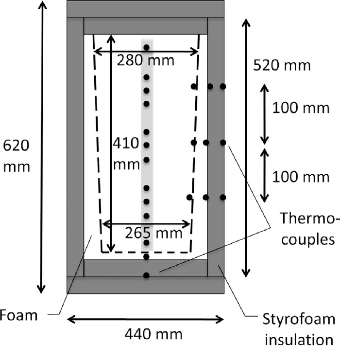
Design sketch of the measurement apparatus. The outline of the container containing pellets is shown in dashed lines. Temperature sensors (thermocouples) are indicated as dots. A vertical string of thermocouples is installed at the center axis of the container (shaded).
Following the concept of Representative Elementary Volumes6), porous materials can be treated as homogenous materials at a scale larger than the components they are comprised of. While the geometry of the setup is three-dimensional, a description is sought of only the onedimensional, vertical thermal diffusion. Allowing for heat exchange with the environment through the insulation, transient, one-dimensional heat transfer is described as
| (1) |
| (2) |
| (3) |
| (4) |
Equation (4) was discretized on a vertical grid of 0.01 m and solved implicitly with the Finite Volume Method (FVM).7) The ambient temperature To increased steadily from 20.5 to 23.5°C over the course of the experiment. The initial temperature profile was a linear interpolation of the measured temperature profile 15 minutes after the pellets had been entered into the system (dotted line in Fig. 2). This was the start of the experiment for the purpose of parameter fitting.
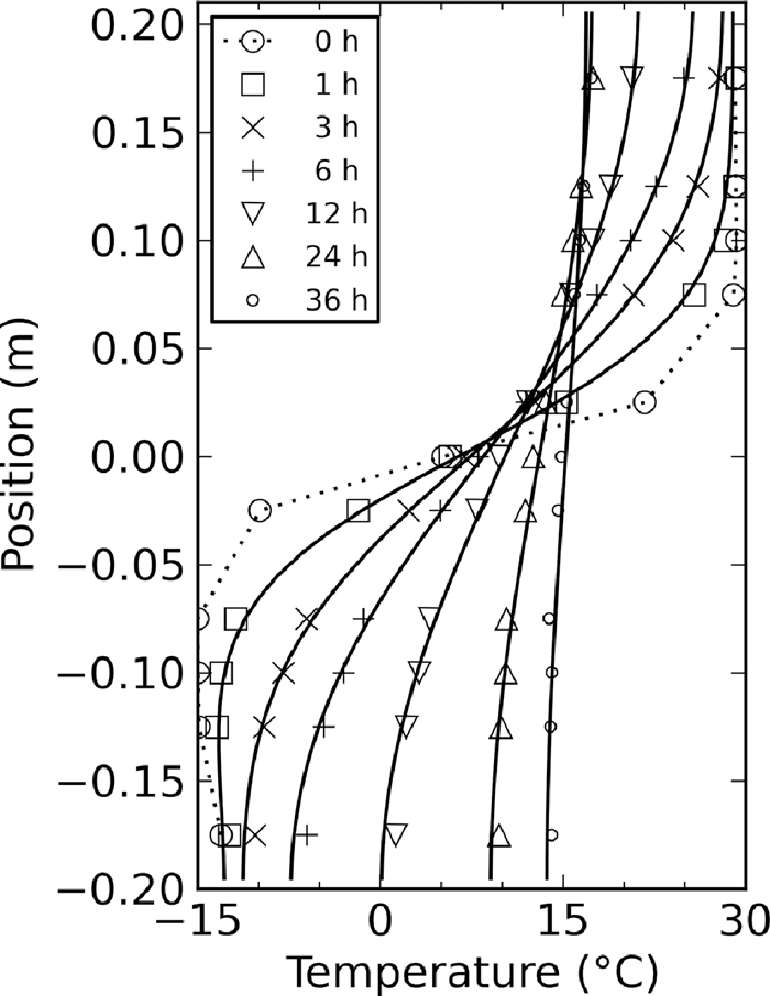
Comparison of measured (data points) and simulated temperature profiles with κ = 2.7×10⁻⁷ m2 s–1 (solid lines). The dotted line is the initial temperature profile used for the simulations, based on corresponding measurements (large circles).
In order to determine constants κ and σ, a least-square minimization was performed of the residual of measured and simulated temperature profiles 0.5, 1, 3, 6, 12, 24, and 36 h after the start of the experiment.
The evolution of measured temperature profiles is shown in Fig. 2. As time progressed, the temperature difference between hot and cold layers diminished. While the expected equilibrium temperature of an adiabatic heat exchange would have been 7.5°C, the average temperature of the pellets was 15°C after 36 hours as a result of heat exchange with the environment. Modeled temperature profiles are shown in Fig. 2 based on least-squares fitted constants κ = 2.7×10⁻⁷ m2 s–1 and σ = 6.1×10⁻⁶ s–1. The modeled temperature profiles match those of the measurements closely, with root-mean-squared (RMS) and maximum error of 0.46 and 1.1°C, respectively.
An uncertainty can be defined for κ based on the sensitivity to choices made for fitting. Specifically, we investigated the best fit parameters for cases where fitting was limited to the first 6 hours, the initial 2 hours (rather than 15 minutes) of data were disregarded, the fit was limited to thermocouples at –100±25 mm (cold), or to thermocouples at 100±25 mm (hot). Results in Table 1 show that κ = (2.51–2.76)×10–7 m2 s–1, i.e. an uncertainty of 6%.
| Modification | Diffusivity κ(10–7 m2 s–1) | Exchange coefficient σ(10–6 s–1) |
|---|---|---|
| Reference case | 2.67 | 6.06 |
| Fit to data at 1, 2, 3, 4, 5, 6 hours | 2.51 | 6.98 |
| Disregard initial 2 h of measurements | 2.76 | 5.93 |
| Fit only data at –100±25 mm | 2.62 | 6.08 |
| Fit only data at 100±25 mm | 2.63 | 5.96 |
The bulk thermal conductivity of a bed of pellets, k, can be estimated from Eq. (2) and literature values of the heat capacity of iron ore. Literature values of iron ore at room temperature fall between c = 550 and 560 J kg–1 K–1,1,8) while the bulk packing density of the pellets used in this experiments was determined to be approximately ρ = 2000 kg m–3. Hence, based on κ =2.7×10⁻⁷ m2 s–1, the bulk thermal conductivity was approximately k = 0.3 W m–1 K–1.
Pellets investigated in this study were dry. However, they can contain moisture and as commercial product may contain <1.2 mass% water. Based on our measurements, they are able to hold up to 5.5 mass% water (to determine this value, pellets were immersed in water and then left to drain). Hence, wet pellets may have a bulk density up to 5.5% higher than dry pellets. Due to the large heat capacity of water of 4200 J kg–1 K–1, c would be expected to increase by up to 40%. The thermal conductivity is expected to be marginally effected by moisture in the pellets. Hence, the thermal diffusivity of wet pellets may be up to 50% lower than of dry pellets. If the water were to be frozen (for ice, c = 2100 J kg–1 K–1) then the reduction of thermal diffusivity could amount to up to 25%. Based on this estimate, moisture could alter diffusivity significantly.
It was found that heat transfer through a bed of dry pellets between –15 and 30°C can be modeled as a homogeneous medium with a temperature-independent thermal diffusivity of κ = 2.7×10⁻⁷ m2 s–1. This value is close to the value of diffusivity within individual pellets,3) which could either be coincidence or the result of a significant contact area between pellets. Diffusivity of wet pellets is expected to be lower, and heat exchange would be retarded even further if a phase transition from ice to water were to be observed. The presented measurement provides a useful reference for heat transfer simulations of dry pellets in harsh weather conditions.
This work was funded by Luossavaara Kiirunavaara Aktiebolag (LKAB) through the Norwegian Railway Technology Center in Narvik, NorJeTS. Analysis and publication were supported by the Research Council of Norway project number 195153. The constructive comments of the anonymous reviewer are gratefully acknowledged.