Regular Article
Physical and Mathematical Models of Vortex Flows During The Last Stages of Steel Draining Operations from a Ladle
2013 年 53 巻 5 号 p. 782-791
詳細
2013 年 53 巻 5 号 p. 782-791
Slag entrainment during steel teeming-drain operations from a steel ladle impacts negatively steel cleanliness and quality. In the present work water modeling and mathematical simulations using a multiphase model for momentum and heat transfer were employed to understand the mechanisms of vortex funnel drain and sink drain flows. The critical bath height for vortex development increases with steel throughput and valve gate opening. Six stages during vortex development are identified, passing from a dimple formation on the bath surface until sink drain which begins when the bath level has the same magnitude as the nozzle diameter. This later drain pattern is independent from any other teeming-draining variable being only a function of the bath height and nozzle diameter; when they are about the same the metal-interface collapses. The temperature gradients originated by the heat losses of the ladle to the surroundings provide buoyancy forces that are large enough to influence liquid motion in the ladle. At large bath levels steel observes long-vertical recirculating flows and at low bath levels these flows change to horizontal-circular recirculating flows that become a seed for later vortex development. These buoyancy forces increase the critical height for vortex development and slag entrainment.
The quantity of liquid steel remaining in the ladle after gate closure is called steel residual and is highly desirable that this residual be as small as possible in order to maximize metallic yield and reduce costs. However, steel teeming operations always represent a danger to cast clean steel due to the severe vortex formation during draining this residual of liquid steel. Entrained slag by the vortex goes to the tundish without apparent deleterious effects on steel cleanliness during casting the first three or even four heats. Nevertheless, during a long casting sequence the recirculating slag particles remaining in the tundish will eventually end in the mould degrading steel quality. Although simple in principle, the formation of vortex in steel ladles is not as easy to understand as is the vortex formed in a bath tube draining water. Some years ago the Group of the authors published works related with mathematical simulations of fluid flow and heat transfer during steel teeming and ladle drain operations.1,2) These reports were preceded by works of other researchers providing important information. For example experimental findings, using water models, indicate that the critical bath height for vortex development (HCr, defined here as the bath level at which a fully vortexing funnel is developed as is described below) decreases when the draining nozzle changes from a centered position to an eccentric one.3,4) Other authors claim that the critical height increases as the steel throughput increases.5,6) Besides, Increases of viscosity ratio μsteel / μslag and density ratio ρslag / ρsteel lead to increases of HCr.3,7) Porto et al.,4) reported that long standstill times after filling a ladle water model decrease HCr. Moreover, Hammerschmidt et al.,8) Steffen9) and Andrzejewski et al.10) reported that residual motions in water levels, such as rotating stirring or tangential water filling increase HCr. Different to those findings, Dubke and Schwerdtfeger11) report null effects of these residual motions on HCr. The critical height is proportional to the ratio of diameters of the nozzle and the ladle, d/D. For a constant ratio d/D, HCr becomes larger with higher initial bath levels.12,13,14)
Vortex development can be described through various stages, in the first there is the development of a bath surface dimple followed by a surface vortex15) in the second stage. The third and fourth stages consist of a deeper vortex formation and development of a fully developed vortexing funnel, hereinafter called here simply as vortex drain. In the last and fifth stage the melt level is so low that the static pressure of the slag layer exceeds that of the steel inducing the collapse of the flow and the slag overwhelms the steel layer exiting through the nozzle well before the last melt; this later stage is usually known as sink drain. Both, experimental and numerical analysis show that sink drain takes place when the height of the steel column is approximately equal to the nozzle diameter.1,10,16,17,18) Some researchers claim that there is not early vortex formation and that slag carryover is observed only during the sink drain flow.16,19,20) However, this is not in agreement with most of the experimental and numerical results1,2,3,4,5,6,7,8,9,10,11,12,13,14,15) since other researchers report vortex drain development before the observation of sink drain flow.
Slag carryover can be controlled by closing the gate once a slag flow is detected using vibration signals (RADAR) or magnetic fields (EM).20) According to those authors RADAR system detects slag carryover at the deeper vortex stage and EM does it at the vortexing funnel formation (stages three and four, respectively). In either case, the gate should be closed before the metal-slag interface collapses making the slag free to flow toward the nozzle. Sink drain sucks all the slag before the last steel residual leaves the ladle, as mentioned above, through the nozzle. In the present paper the vortex mechanisms are analyzed through physical modeling and mathematical simulations. Detailed knowledge of vortex mechanisms will essentially allow designing flow control devices aimed at minimizing slag carryover during vortex drain and sink drain flows. The difference between the present work and those of others3,4,5,6,7,8,9,10,11,12,13,14,16,17,18,19,20) is the study of the contribution of buoyancy forces to enhance vortex drain mechanism. Here we use the approach of water modeling complemented with a mathematical-multiphase flow model under isothermal and non-isothermal conditions to perform deeper understanding of the transport phenomena involved during teeming-draining operations of liquid steel. Implications of this basic knowledge will eventually lead us to find out a flow control device that should be helpful to decrease the critical height of vortex drain and to diminish the amount of slag carryover during sink drain flows.
The 1/3 scale water model corresponds to a ladle (150 ton of steel) from a seamless pipe maker in Mexico, the dimensions of this model made of transparent plastic are shown in Figs. 1(a) and 1(b). The position of the nozzle is eccentric and the valve gate was also replicated at 1/3 scale. In the wall of the ladle beside the valve gate a water chamber, with a flat outer wall, was fixed in order to avoid excessive laser light reflections allowing using a laser sheet of a Particle Image Velocimeter (PIV) equipment. The laser sheet was focused on a horizontal plane parallel to the ladle bottom at the level of the outlet to be able to capture the flow during vortex flows. The nozzle diameter is 20 mm and the slide gate has four fixed openings corresponding to 100%, 75%, 50% and 25% of the total outlet area. A stirrer composed by a shaft and a paddle at its end with half the mean ladle diameter, 15 mm thick and a height of 150 mm was used to stir the bath at a constant speed of 100 RPM. The paddle was located 200 mm from the ladle bottom. The objective of the stirring operation was to observe the influence of the residual motions on Hcr. For that purpose 10 minutes after ladle filling the bath was stirred during 0, 5, 10 and 15 minutes and after that the water draining experiments were performed from the full level (corresponding to 150 tons) at a gate opening of 100%. From the top of the ladle a dropping of red dye tracer was performed, through a syringe, over the position of the outlet to visualize the vortex formation during drain experiments. Scales to measure water levels were pasted in the outer ladle wall. Readings were recorded by a video camera placed just in front of the valve. Figure 2 shows a scheme of the full experimental setup used in this investigation. Table 1 shows a summary of the experimental and simulation activities involved in the present work and Table 2 shows the relationship between bath level and steel tonnage for this ladle which has an inclined bottom of 20. All experiments were performed at a constant room temperature of 298 K.
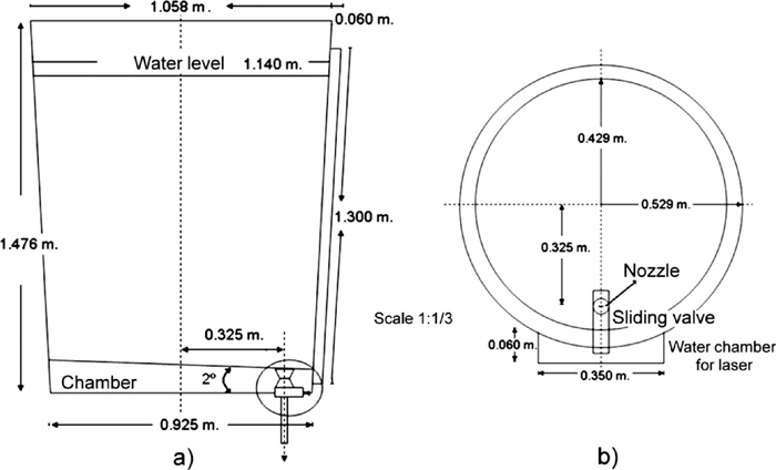
Dimensions of the ladle model at 1/3 scale of the actual ladle.
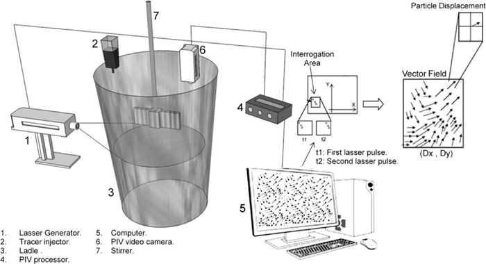
Experimental setup.
| Type of Experiment | Description |
|---|---|
| Teeming from full bath level Without oil layer | No-oil, initial bath level is maintained constant and corresponds to the ladle completely filled at 150 tons. Valve openings are 100%, 75% 50% and 25% |
| Teeming from full bath level With oil layer | Oil layer, initial bath level is maintained constant and corresponds to the ladle completely filled at 150 tons. Valve openings are 100%, 75%, 50% and 25% |
| PIV measurements | Detection of vortex drain through PIV measurement |
| Mathematical model of the multiphase system | Includes simulations under constant steel temperature and under the presence of temperature gradients |
| High Tonnage | Low Tonnage | ||
|---|---|---|---|
| Height (Meters) | Capacity (Tons) | Height (Meters) | Capacity (Tons) |
| 3.20 | 150.13 | 0.70 | 30.33 |
| 3.10 | 144.99 | 0.60 | 25.91 |
| 3.00 | 139.87 | 0.50 | 21.52 |
| 2.90 | 134.66 | 0.40 | 17.16 |
| 2.80 | 129.73 | 0.30 | 15.31 |
| 2.70 | 124.70 | 0.28 | 14.55 |
| 2.60 | 119.70 | 0.27 | 13.79 |
| 2.50 | 114.74 | 0.25 | 13.03 |
| 2.40 | 109.80 | 0.24 | 12.27 |
| 2.30 | 104.89 | 0.22 | 11.51 |
| 2.20 | 100.01 | 0.21 | 10.74 |
| 2.10 | 95.35 | 0.19 | 9.98 |
| 2.00 | 90.35 | 0.18 | 9.22 |
| 1.90 | 85.56 | 0.16 | 8.45 |
| 1.80 | 80.80 | 0.15 | 7.69 |
| 1.70 | 76.06 | 0.13 | 6.92 |
| 1.60 | 71.36 | 0.12 | 6.15 |
| 1.50 | 66.06 | 0.10 | 5.39 |
| 1.40 | 62.04 | 0.09 | 4.62 |
| 1.30 | 57.43 | 0.07 | 3.85 |
| 1.20 | 52.84 | 0.06 | 3.08 |
| 1.10 | 48.28 | 0.04 | 2.31 |
| 1.00 | 43.75 | 0.03 | 1.54 |
| 0.90 | 39.25 | 0.01 | 0.77 |
| 0.80 | 34.78 | 0.00 | 0.00 |
Physical modeling was complemented and supported by mathematical simulations of steel drain operations under isothermal and non-isothermal conditions. Steel flow in ladles is basically controlled by the sinking flow of cold steel along the wall forming a well defined boundary layer. This sinking flow is originated by the energy losses from the ladle to the surroundings. Therefore, liquid steel in the proximities of the ladle wall gets colder increasing its density and leading to a downward flow from the top to the ladle bottom. To simulate such a particular flow the SST k-ω model of turbulence is considered as the most appropriate,2) because it is a blend of the k-ω model of turbulence with more predictive capabilities for boundary layers21) and the k-ε model22) which has better capabilities for bulk flows. Figure 3 shows a scheme of this blending of turbulent models. This model blends turbulence models, k-ε and k-ω, through a cross-diffusion modification given by,
| (1) |
| (2) |
| (3) |
| (4) |
| (5) |
| (6) |
| (7) |
| (8) |
| (9) |
| (10) |
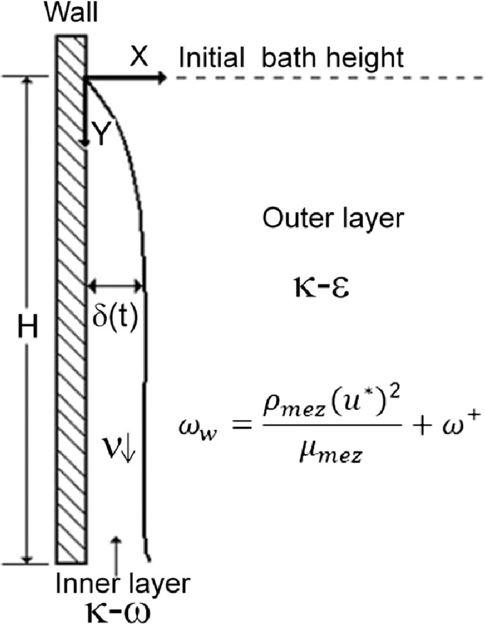
Blending of turbulence models. Model k-ω for the boundary layer in the ladle wall and model of turbulence k-ε for fluid flow in the region far away from the boundary layer.
| Property | Symbol | Value | Units |
|---|---|---|---|
| Density of steel | ρm | 710+ (T–Tmp)(–0.833) |
|
| Thermal conductivity | km | 41 |
|
| Thermal Capacity | Cpm | 750 |
|
| Viscosity | μm | 0.006 | Pa-s |
| Density of air | ρa | 1.225 |
|
| Thermal conductivity | ka | 0.0242 |
|
| Thermal Capacity | Cpa | 1006.43 |
|
| Viscosity | μa | 1.789×10⁻⁵ | Pa-s |
| Density of slag* | ρs | 2750 |
|
| Thermal Conductivity | ks | 6.69 |
|
| Thermal Capacity | Cps | 780 |
|
| Viscosity | μs | 0.13 | Pa-s |
| Interfacial tension | Σ | 1.3 |
|
In the ladle shroud the magnitudes for k, ε and ω were calculated with the following equations,
| (11) |
| (12) |
| (13) |
The influence of residual motions on vortex formation is shown in Fig. 4 with a 100% opening gate; as seen instead of increasing the magnitude of Hcr with increases of stirring time it actually decreases. With 5 or 10 minutes of pre-stirring times the vortex develops at lower bath levels. When the pre-stirring time goes to 15 minutes the magnitude of Hcr is about the same as the case when stirring was not applied at all. These results are in disagreement with those reported by Hammerschmidt et al.,8) Steffen9) and Andrzejewski et al.10) who reported effects of residual motions that increase Hcr, but agree quite well with those reported by Dubke and Schwerdtfeger11) in the sense that residual motions have little or null influence. For any practical purposes the differences of Hcr for these experimental conditions are very small and this variable can be considered as independent from the rotation energy imparted to the fluid.

Effect of the pre-stirring time on the critical height for vortex funnel drain.
Drain experiments include those without an oil layer and those with a oil layer in order to determine the influence of a lighter phase on the magnitude of Hcr. Figs. 5(a) and 5(b) correspond to measurements of Hcr magnitudes for a valve opening of 100% and 50%, respectively and make evident the influence of this variable. Figure 6 shows the relation between valve opening and the critical height for vortex drain. The higher the opening of the valve is the higher is the magnitude of Hcr as indicated by the dye tracer and plotted in that figure. It is important to notice a well defined surface dimple. The presence of an oil layer increases Hcr as seen also in Fig. 6 indicating that the static pressure of a lighter phase enhances the formation of vortex drain flows. PIV measurements of the velocity field at drain levels (0.05 m from the bottom for a total level of 0.07 m) is shown in Fig. 7 where the vortex drain is clearly seen around the nozzle.
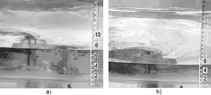
Vortex funnel development. a) Valve 100% open. b) Valve 75% open.
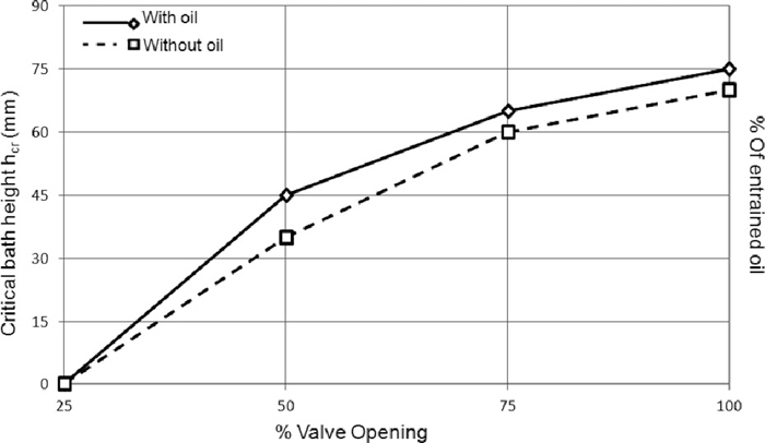
Effects of valve opening on % of entrained oil and on critical height for vortex funnel development.
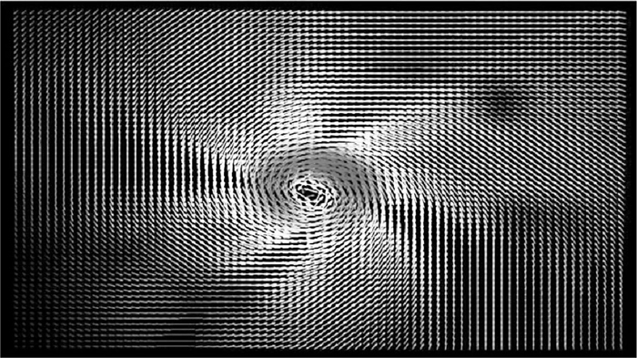
Velocity field during vortex drain development for a valve opening of 100%.
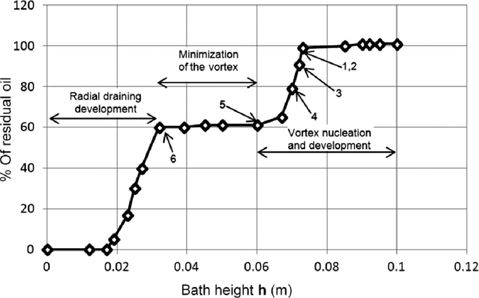
Direct observations of this model using the oil layer lead to more detailed development stages of vortex drain and sink drain flows. Indeed, vortex development is preceded by a surface dimple as those observed in Figs. 5(a) and 5(b) identified through dye tracer. At the beginning, and once that the dimple is formed (Fig. 8(a)) the vortex develops and is characterized by a weak vibrating tail, Fig. 8(b). The next stages consist of a vortex with a strongly vibrating tail, Fig. 8(c) followed by a stable non-vibrating tail vortex, Fig. 8(d). The next stage indicates that the vortex is instable and disappears, Fig. 8(e), and later on comes the time when the oil pressure exceeds that of the water column (water bath height has a magnitude of about the ladle nozzle diameter) and the water-oil interface collapses forming a sink drain, Fig. 8(f). The drain stages can be clearly identified in the oil entrainment curve of Fig. 9. Surface dimple is formed just some 5 mm before vortex drain development and about 40% of the oil is entrained toward the ladle shroud when the vortex with, first weak and later strong, vibrating tail is observed followed by a well developed vortex with a stable tail. After total vortex development there is a plateau where the vortex disappears and oil entrainment stops and this precedes the last stage when the water-oil interface collapses allowing all oil flowing out (the rest 60% of the total initial amount of oil) before the last water layer remaining in the ladle bottom leaves. As the valve gate is gradually closed the amount of entrained oil and the magnitude of Hcr decrease since the bath level for flow collapse decreases also as is seen in Fig. 6. When the valve gate is 25% open there is not formation of vortex drain but the sink drain persists independently of any experimental condition.
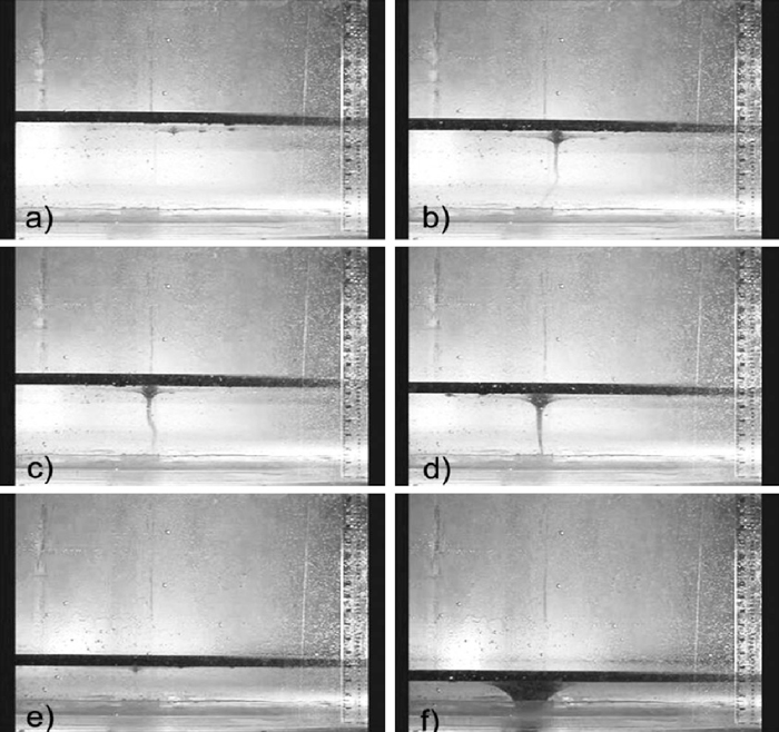
Development stages of the vortex funnel development and oil entrainment. a) Surface dimple starts, b) Development of a shallow vortex with weak vibrating tail, c) Development of a deep vortex with tail vibrating strongly, d) Vortex stabilization without a vibrating tail, e) The vortex becomes instable and disappears, f) development of drain sink mechanism.
Effects of valve opening on % of entrained oil and on critical height for vortex funnel development.
The critical height for vortex formation, Hcr, under isothermal conditions (no heat loses from the ladle) was calculated through the mathematical model and resulted to be 210 mm which looks in excellent agreement with the figure of 75 mm determined by the water model (without oil layer) considering that the ladle model is 1/3 scale and the scale up criterion is based on the Froude number. Therefore, it is concluded that water drain in the ladle model is essentially similar to that of steel drain in the actual ladle if steel in a ladle would flow hypothetically without heat loses. Indeed, as Davila et al. reported2) flow pattern during teeming operations at high bath levels under isothermal conditions consists of a steel stream directed toward the outlet with absence of any ascending fluid due to the non-existence of buoyancy forces (see their Fig. 3(a)).
4.2. Mechanisms of Vortex Onset and Vortex Development under Non-isothermal ConditionsFluid flow pattern of liquid steel in a vertical-symmetric plane, expressed through stream lines, in the ladle at full capacity of 150 ton after a standstill time of 15 minutes in the caster turret is shown in Figs. 10(a) and 10(b) for the velocity vectors and streamlines, respectively. Two big recirculating flows are formed in the central part of the ladle by hot steel flowing upwards and once reaching the bath top steel flows downwards along the walls (see also Fig. 11(a) to follow the orientation of the velocity vectors at a lower bath level). Vortex sheets are observed along the ladle wall which are generated by shearing stresses induced by the downwards flow of denser steel along the ladle wall and the warmer and less dense steel floating further inside the ladle. In the ladle bottom, in a position located opposite to the ladle shroud, marked with number “1” in Fig. 10(b), the recirculating flow is divided in two streams; one continues ascending through bath height and the other is cooled down by the heat losses through the ladle bottom and flows downwards toward the nozzle. In the meantime, steel which is about to flow towards the nozzle is sheared by the lowest vortex flow in the wall and drives it upwards as is indicated by number “2” in Fig. 10(b). This fluid flow pattern in the bottom, in the proximities of the nozzle, inhibits the formation of a vortex funnel working as a curtain to impede the impact of the horizontal steel stream (along the ladle bottom) with the ladle wall. Therefore, it is difficult to have vortex drain funnels at high bath levels and these types of flows are developed at lower levels as indicated in Figs. 8(a)–8(f) in the water model. Indeed, the mathematical simulations, under the influence of temperature gradients, indicate that vortex funnel starts at a level of 350 mm with a slide gate opening of 100% which is the same condition used in the experiments shown in Figs. 5(a)–5(b). Velocity fields of liquid steel at different bath levels in a vertical-symmetric plane, during teeming are shown in Figs. 11(a), 11(b), 11(c) and 11(d) for bath levels of 2.8, 2, 1.5 and 0.35 m, respectively. When the bath level is high, the vertical and long recirculating flows of steel persist (Fig. 11(a)). However, at a level of 2 m (Fig. 11(b)) those vertical flows suffer a transition from vertical to horizontal flows and at low bath levels (Figs. 11(c) and 1(d)) the predominance are circular-horizontal flows that will, eventually, induce the vortex drain flows at lower steel drain levels. Velocity fields at horizontal planes located at bath levels of 0.8, 0.40 and 0.20 m for a total bath level of 1.5 m are shown in Figs. 12(a), 12(b) and 12(c), respectively. In this later figure is seen that the buoyancy forces generate streams (marked with numbers “1”, “2” and “3”) that enhance the formation of a vortex drain. Therefore, at high bath levels the momentum transfer in the vertical direction exceeds that in the horizontal. As the bath level decreases the vertical momentum flux decreases and the horizontal and angular momentum increase. Also, in these figures is seen that there are circular-horizontal flows of steel mainly at the level of 0.40 m and at a level of just 0.20 m the vortex is not yet well defined. Temperature fields, during steel teeming and drain operations, at bath levels of 2.8, 2.0, 1.15 and 0.35 m are shown in Figs. 13(a), 13(b), 13(c) and 13(d), respectively. It is evident that as steel cools down the temperature gradients decrease. However, as can be seen in Fig. 13(d), at drain levels as small as 0.35 m these temperature gradients are still large enough to maintain appreciable buoyancy forces that contribute to the vortex formation. Those thermal gradients enhance buoyancy forces which have a definitive influence on velocity fields. Even at the lowest bath level of 0.35 m the thermal gradients are large enough to induce considerable momentum to the liquid steel as can be seen in Figs. 11(c) and 11(d). In summary, three magnitudes of the bath height where the water-oil interface becomes instable (vortex onset) previous to the formation of a well developed vortex funnel are identified; the first is in the water model which yields a magnitude of 80 mm (with an oil layer). The second is three times that height considering that the scale of the model is 1/3, i.e., 240 mm (12 tons of residual steel in ladle) which agrees very well with the bath height of 210 mm (11 tons of residual steel in ladle) obtained from the mathematical simulations under the hypothetical-isothermal conditions, no heat losses. Indeed, the third bath height for vortex onset is observed in Fig. 14(a) which is about 350 mm (15 tons of residual steel in the ladle). Therefore, vortex onset is about 110–140 mm higher under non-isothermal conditions and a well developed vortex is observed, as expected, at lower bath levels as is seen in Fig. 14(b). It seems then that the inclination of the ladle bottom and the buoyancy forces originated from the thermal gradients provide the angular momentum transfer to enhance the vortex onset. Figure 15 relates the critical bath heights for vortex onset derived from the experimental observations in the isothermal water model, from the hypothetical steel flow under no-heat losses from the ladle walls and the critical bath height considering heat losses and the implicit buoyancy forces. This figure makes clear the contribution of buoyancy forces on the critical bath height and the acceptable similarity between water flow conditions and steel flow assuming isothermal conditions.
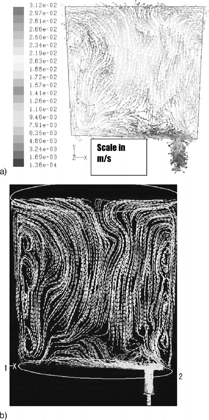
Velocity vectors. b) Stream lines of liquid steel flow in the ladle developed after a standstill time of 15 minutes in the caster turret, 1) Flow conditions in the opposite side of the nozzle, 2) Shear free flow close to the nozzle originated by the downwards cold steel flow along the ladle wall.
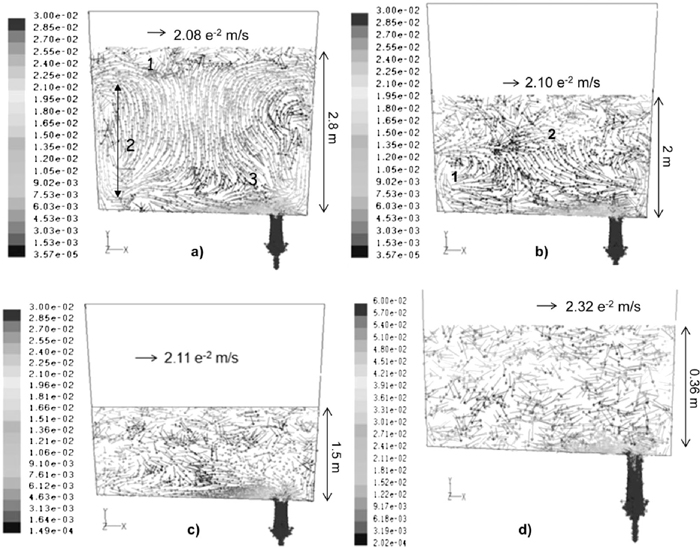
Velocity fields in a central plane of the ladle at different steel bath levels during a teeming-drain operation. a) Bath level is 2.8 m, b) Bath level is 2.0 m, c) Bath level is 1.5 m and d) Bath level is 0.35 m.
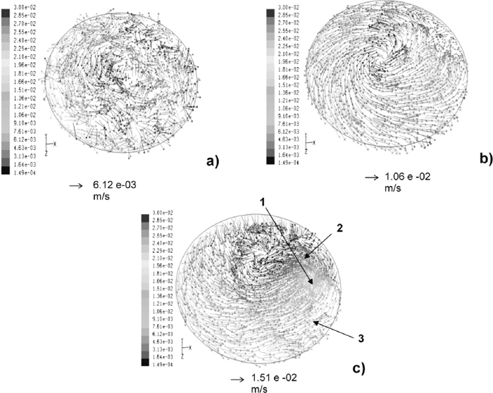
Velocity fields in horizontal planes of the ladle at different steel bath levels during a teeming-drain operation. a) Bath level is 2.8 m. b) Bath level is 2.0 m. c) Bath level is 1.5 m.
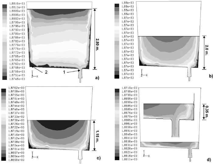
Temperature fields of steel in the ladle at different bath levels during a teeming-drain operation. a) Bath height is 2.8 m, b) Bath height is 2.0 m, c) bath height 1.15 m and d) Bath height is 0.35 m.
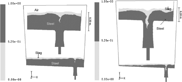
Mathematical simulations of slag entrainment by a vortex funnel drain mechanism during a steel drain operation. a) Shallow vortex. b) Complete slag entrainment by funnel vortex.
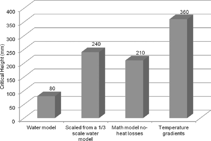
Summary of critical bath heights for vortex onset determined through different approaches.
The mechanism can be summarized as follows; Cold steel creeping in the ladle bottom transfers momentum to the upper hot steel layer in regions close to the nozzle seen Fig. 16(a). In the opposite side of the nozzle steel flows also along the ladle bottom, following a creeping flow, driven by buoyancy forces originated from to its higher density in comparison with the hot steel with a lower density located in the proximities of the nozzle, see Figs. 16(b) and 16(c). Steel shears the metal-slag interface and the slag layer receives momentum from the metal phase being dragged together with steel toward the ladle wall. The two-phase flow, steel and slag, impacts the ladle wall and is later deviated inwards and is finally captured by the velocity field of the vortex in the nozzle. As reported by Davila et al.2) steel drain under isothermal conditions gives origin to a well defined vortex drain driven by the gravity force or gravity component acting on the inclined plane. This is in quite agreement with the experimental observations in the water model as reported in Figs. 5 and 6. Therefore, the buoyancy forces simply enhance this effect and that explains the higher magnitude of Hcr under non-isothermal conditions than that corresponding under isothermal conditions.
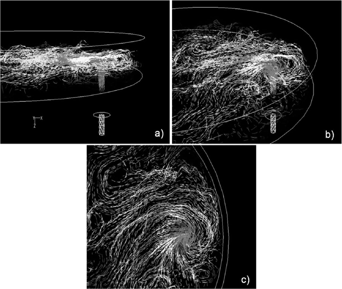
Mathematical simulations of steel flow revealed through stream lines during a drain operation of residual liquid steel from the ladle.
According with the results of this research during the of vortex onset and vortex development (stages 1–4 in Figs. 8(a)–8(d)) the slag entrained into the stream toward the tundish represents only about 0–40%, depending on the valve opening, of its original amount in the ladle. Besides, any slag control system, vibrating or magnetic, operating in the outlet region have the main purpose to detect rather than prevent sink drain flows. Slag detector systems would be eventually helpful to close the valve gate during vortex drain flows but the amount of residual steel will be still considerably high decreasing then the metallic yield. Even the modification of the ladle bottom to avoid slag carryover during steel drain operations is limited only during the developments of the vortex onset-vortex drain flows.19,20) In practical terms, any device that may decrease the critical height for vortex drain flow onset will avoid the passage of slag during this stage. However, the maximum efficiency of such device would imply leaving 100% of the slag available for sink drain, which does not seem to be particularly attractive. Therefore, all efforts to solve the problem at hand must be focused on how to decrease slag carryover during drain sink flows.
Water modeling and multiphase flows and heat transfer simulations were used to study the mechanisms of slag entrainment during teeming and draining operations of steel form a ladle. The physical model involved techniques such as video recording, PIV and red dye dropping to characterize vortex flows. The multiphase model includes the steel, slag and air phases. The conclusions derived from this study are as follows:
(1) The physical modeling and the mathematical simulations indicated the existence of vortex funneling drain during steel drain operations. The critical bath height for vortex development increases with steel throughputs and valve opening.
(2) Vortex funneling mechanisms involve six stages: a) Surface dimple formation. b) Shallow vortex with a weak vibrating tail. c) Stabilization of the funnel vortex with strongly vibrating tail. d) Deep funnel vortex without vibrating tail. e) Instable vortex and interface stabilization. e) Sink drain at a bath level equal to the nozzle diameter.
(3) Upper phase entrainment (oil in the water model or slag in the actual ladle) increase with steel throughput and valve opening. At valve opening of 25% the vortex is not developed and slag entrainment is close to zero. However, sink drain flow remains.
(4) Fluid patterns, affected by buoyancy forces in the actual ladle, observe long-vertical recirculating flows in the melt volume. As the bath level decreases during steel teeming the flow patterns shift to horizontal-circular flows that represent the seed for vortex formation at lower levels. At high bath levels the cold steel stream flowing along the ladle wall develops vortex sheets along all the bath height due to its interaction with inwards hotter steel. The last vortex in the bottom, close to the nozzle, impedes the impact of the cold steel stream, flowing along the ladle bottom toward the nozzle, to impact the ladle wall. This effect avoids the formation of vortex flows in the nozzle.
(5) Buoyancy forces increase the critical height for vortex development through enhanced momentum transfer by the cold steel flowing along the ladle bottom. This stream mixes with the hotter steel located closet to the nozzle and the multiphase flow impacts the ladle wall to develop the vortex flow at low steel levels (in the present case at 0.35 m).
The authors acknowledge to IPN for the permanent support to the Process Metallurgy Group at ESIQIE, Department of Metallurgy and Materials Engineering. Thanks are also given to the institutions, SNI, COFAA, CoNaCyT and PIFI, for the scholarships and financial support granted to the participants in this research.