Regular Article
Thermal Analysis of Strip in Multi-bending Process After Hot Rolling
2013 年 53 巻 5 号 p. 874-879
詳細
2013 年 53 巻 5 号 p. 874-879
The thermal histories of steel strips in a multi-bending process after hot rolling were clarified by numerical analysis in order to investigate the appropriate conditions for grain refinement. The temperature oscillates cyclically at the strip surface, whereas the temperature amplitude is relatively small at the center of thickness. The temperature distribution in the strip thickness direction depends on the transfer speed and cooling conditions, that is, air or water cooling. In industrial production, water-cooling equipment would be necessary in order to cancel the accumulated heat generation caused by bending deformation and to maintain the strip temperature in the appropriate range for grain refinement.
Since the strength, toughness, fatigue resistance, and coating property of steel products can be improved by grain refinement, technologies for producing fine grained steel are now an area of active studies.1,2,3,4,5,6) In the past, many studies examined grain refinement by applying large strain. In order to obtain fine grained hot-rolled steel sheets, above all, it is widely recognized that rapid cooling is necessary after large deformation of austenite at relatively low temperature.7,8,9,10,11) It has also been reported that manufacturing hot-rolled steel sheets with an average ferrite grain size of about 2 μm is possible.12)
In general, controlled rolling11) is applied to steels which contain added strengthening elements such as Ti, Nb, V and so on. However, the use of these relatively rare elements increases manufacturing costs. From the viewpoints of resource security and the price competitiveness of products, which include high tensile steel sheets for automotive applications, it is very important to develop a technology for manufacturing fine grained steel with minimal addition of strengthening elements.
In recent years, the PROTEUS project13) was carried out with the final target of establishing an industrial manufacturing process which realizes a steel sheet with a ferrite grain size of 1 μm. In this project, a variety of manufacturing processes such as hot rolling with large accumulated strain,14) hot forging15) and multi-bending after hot rolling16) were proposed.
For manufacture of fine grained steel, the authors proposed a multi-bending process after hot rolling. The results of laboratory tests were presented, and the presumed mechanism of grain refinement was introduced.16) In steel manufacturing processes, deformation employing bending strain can be seen in the tension leveler and roller leveler, which are used for sheet flatness control. However, in these processes, very small bending strain is applied at room temperature. As the temperatures of the material and manufacturing equipment do not become a problem, there have been no detailed reports concerning thermal analysis.
In contrast, in the multi-bending process after hot rolling, bending deformation is applied repeatedly and accumulative strain is relatively large. Therefore, the fact that heat generation due to deformation is inhomogeneous in the thickness direction should be taken into account. The heat transfer phenomena are also complicated because the sheet undergoes repeated heat transfer by contact with the bending rolls, water-cooling and air-cooling within a very short time. As the thermal condition when strain is applied strongly affects grain refinement, the type and amount of strain should be well understood. Moreover, accurate prediction and control of the thermal history of the sheet at various points in the thickness direction are also important.
In this research, the authors attempted to obtain a ferrite grain size of less than 2 μm at the strip surface as the target for ferrite grain refinement. In order to clarify the details of the thermal history of the steel sheet in this process, the thermal boundary condition was quantified based on measured data obtained in a laboratory test, and a thermal analysis was then carried out based on the conditions used in industrial production.
Figure 1 shows an overview of the experimental apparatus, and Table 1 shows its specifications. An electric furnace, rolling mill, 3 multi-bending equipments and water-cooling equipment are set in a laboratory rolling line. Pyrometers are installed at the entry side of the mill and exit side of every equipment. The temperatures were measured before and after deformation and cooling.
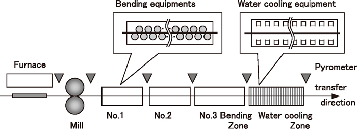
Schematic illustration of laboratory facility.
| Strip | Thickness | 3 mm |
| Rolling temperature | 800–1050°C | |
| Transfer speed | 1.0 m/s | |
| Bending Roller | Diameter | 50 mm (No.1,2), 70 mm (No.3) |
| Roller pitch | 65 mm (No.1,2), 90 mm (No.3) | |
| Maximum vertical offset | 7 mm (No.1,2), 8 mm (No.3) | |
| Maximum total pass | 19 × 2 + 21 = 59 | |
| Maximum total strain at surface | 0.0446 × 38 + 0.0259 × 21 = 2.2 |
A sample was cut out to the length of 1200 mm and width of 100 mm from a hot rolled steel sheet with the thickness of 10 mm. The chemical composition of the sample was 0.15 mass% C, 0.01 mass% Si and 0.75 mass% Mn. Thermocouples were welded to the surface to monitor the reheating temperature.
In the laboratory test, after the sample was reheated to the designated temperature, which was in the range of 900°C–1200°C, by reheating for about 30 minutes in the electric furnace, oxide scale was removed by striking with a hammer. When the pyrometer at the entry side of the mill indicated the designated temperature, the sample was deformed to the thickness of 3 mm by 1 pass rolling with 70% reduction. Accumulative strain with a maximum value of 2.2 at the surface was applied by passing the sample in the 3 multi-bending equipments, which comprised 21 to 23 bending rollers. Vertical offset, which is downward vertical shift of the upper bending rollers from the state of contact with a flat sheet, was from 7 to 8 mm. Finally, the sample was cooled rapidly by passing through water-cooling equipment, in which water was supplied from spray nozzles. The transfer speed was kept constant at 1.0 m/s from the exit of the mill to the exit of the cooling equipment.
2.3. Experimental ResultsFigure 2 shows the effects of the rolling temperature and applied bending strain on the ferrite grain size dα(μm) at the surface in the final microstructure. This experiment confirmed that the ferrite grain size becomes smaller under conditions of lower deformation temperature and larger accumulative strain.
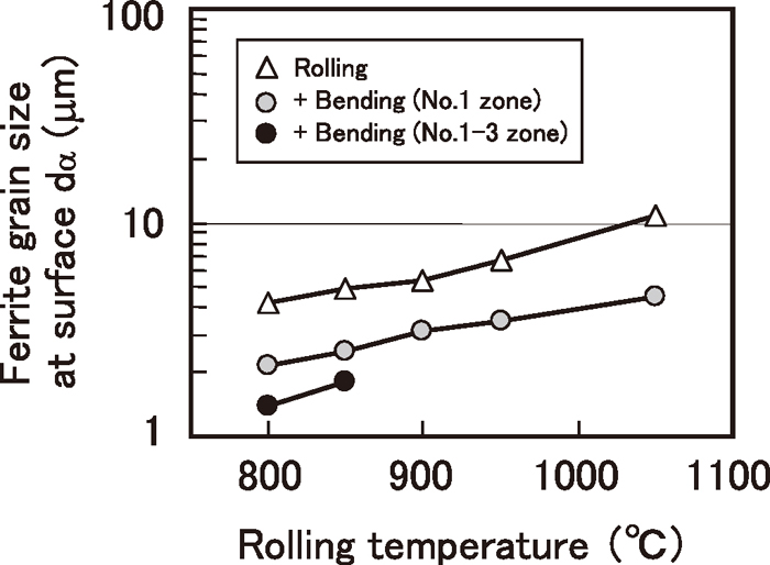
Effect of rolling temperature on ferrite grain size at surface.
Figure 3 shows SEM photographs of the surface microstructure obtained with accumulative strain of 2.2. Using rolling temperatures of 850°C and 800°C, fine polygonal ferrite microstructures with grain sizes of 1.8 μm and 1.4 μm, respectively, were obtained.
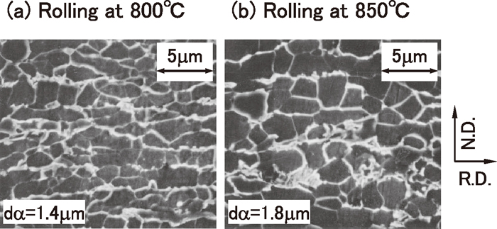
Microstructure Photograph (Bending at No.1–3 zone after rolling).
Figure 4 shows the strip temperatures measured by the pyrometers when the ferrite grain size of 1.4 μm was obtained. The strip temperature was 800°C at the entry side of the mill, and decreased to 770°C after 1 pass rolling and to 730°C after passing 3 bending zones. The temperature after spray water cooling was 550°C.
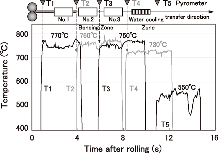
Measured Temperature in laboratory test.
Matsubara et al. verified that the Ar3 temperature was approximately 750°C and applying bending strain repeatedly at a temperature of 750–770°C is most effective for grain refinement. As illustrated in Fig. 4, the temperatures T1, T2 and T3, which were measured at the entry side of the 3 multi-bending equipment, were well controlled to appropriate values.
Water cooling was performed with the target of <550°C, at which ferrite grains do not grow, and the temperature of the sample was controlled successfully. It is assumed that the relatively large temperature deviation is due to the unstable conditions which are characteristic of laboratory tests. Namely, in comparison with production under industrial conditions, it is difficult to obtain uniform spray cooling performance at the strip surface due to the slower transfer speed in the laboratory. Water splashing also occurs in the laboratory cooling equipment, which is enclosed by shield boards, and the oxide scale is thick and its sticking condition varies widely. These are all possible factors influencing temperature deviation.
2.4. Model of Thermal AnalysisAs the rolling time and bending time are very short, heat conduction in the rolling direction and strip width direction is negligible. Therefore, the thermal histories in the steel strip were simulated by the difference method considering only heat conduction in the thickness direction.
In previous studies of rolling temperature analysis, a symmetric model across the thickness direction was generally used.17) However, in the present research, an asymmetric model was used, as the strip comes into contact with the bending rollers alternately at the upper side and lower side in the multi-bending process. T, the temperature inside the strip, is expressed by the heat conduction equation shown in Eq. (1) using Y, which is the distance from the center of strip thickness.
| (1) |
Where t is time (s), λ is thermal conductivity (W/m K), c is specific heat (J/kg k), ρ is density (kg/m3) and q is the heat generation rate by deformation (W/m3). For thermal conductivity, specific heat and density, data from the literature,18) which were reported for steel with 0.23 mass% C, were used.
As boundary conditions at the upper and lower strip surfaces, heat transfer coefficients during contact with the bending rollers and during non-contact cooling were given alternately. Heat flux Q at the upper and lower surfaces (Y=±h/2), where the strip thickness is h (3 mm), is expressed by Eq. (2).
| (2) |
Q in air cooling and water cooling is expressed by Eq. (3), (4), (5), and Q in contact with the bending rollers is given as Eq. (6).
| (3) |
| (4) |
| (5) |
| (6) |
Where Qrad is heat flux of radiation (W/m2), Q1 is heat flux in cooling by air or water (W/m2), Q2 is heat flux in contact with bending rollers (W/m2), σ is the Stefan-Boltzmann constant (5.67×10⁻⁸ W/m2 K4), ε is emissivity (constant of 0.8), Ts is the strip surface temperature (K), Ta is the temperature of the coolant (air of water) (K), Tx is the strip surface temperature (303 K) and Δt is the time step in thermal analysis. It was assumed that the heat transfer coefficients were independent of time.
The heat generation rate q was given as Eq. (7), using strain εb, which is a function of the position in the thickness direction. The distribution of bending strain in the thickness direction was given as Eq. (8), which was expressed as an approximation of the results of the deformation analysis by Matsubara.16)
| (7) |
| (8) |
Where, km is deformation resistance, εc and εs are equivalent plastic strain at the center of thickness and surface, respectively, and h is thickness (3 mm). Deformation resistance was given as 196 MPa, which was calculated from the actual rolling force in the laboratory test.
2.5. Results of Temperature AnalysisFigure 5 shows the thermal histories, which are the results of the strip temperature analysis in multi-bending. The result of the analysis using 3000 W/m2 K as the heat transfer coefficient during contact with the bending rollers shows good agreement with measured strip temperature in the laboratory test.
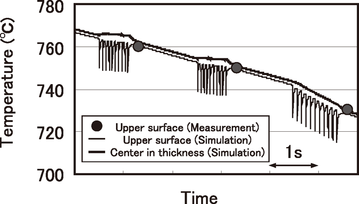
Comparison of bending temperature between simulation and measurement.
Temperature drop and thermal restoration are repeated at the upper and lower surfaces, and the thermal amplitude is 14°C. The pass time in the multi-bending equipment is less than 1s. Whereas the temperature drop in No. 1 and No. 2 zones is 4°C, that in No. 3 zone is larger, being 14°C. In No. 3 bending equipment, the diameter of the bending roller and the vertical offset are larger than in other equipments. Therefore contact length between the strip and rollers becomes longer and larger temperature drop was estimated.
Figure 6 shows the details of the thermal histories during passing in No. 1 multi-bending equipment. As this equipment comprises 10 upper rollers and 11 lower rollers, rapid temperature drop at the upper surface during contact with the upper rollers occurs 10 times. This research clarified the fact that a thermal cycle, which is defined as the time from start of contact with a roller to the next contact, was repeated and that cycle consisted of 4 steps, as illustrated in Fig. 7. When the strip comes into contact with an upper roller, the upper surface temperature of the strip drops rapidly due to heat transfer to that roller, as shown in (a). After contact with the roller is complete, the upper surface temperature begins to rise by thermal restoration, as shown in (b). When the lower surface comes into contact with a lower roller, bending strain is applied and the rise in the upper surface temperature is accelerated due to heat generation by deformation, as shown in (c). As greater heat generation occurs closer to the surface, the thermal graduation around the upper surface is small at the end of contact with a lower roller, and subsequent temperature rise is slowed, as shown in (d).
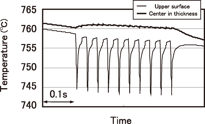
Simulated thermal histories in laboratory test condition.
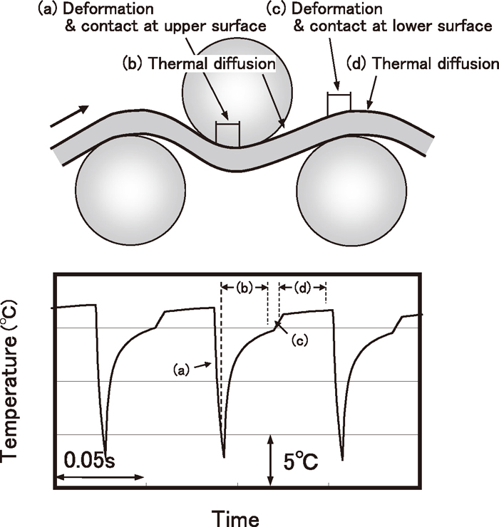
Cyclic change in Upper surface temperature.
Although the influence of heat generation due to strain can also be seen at the center of thickness, the rise in temperature is as small as 0.2°C/pass.
As the transfer speed in industrial production is higher than in the laboratory test, the contact time with the bending rollers is shorter and the heat transfer per bending pass is smaller. Therefore, in order to inhibit temperature rise during bending and accumulate strain in the strip at a temperature just above the Ar3 point or in the temperature range of super-cooled austenite, it is necessary to apply more intensive inter-bending pass cooling than in the laboratory test. The authors attempted to clarify these problems, which are characteristic of industrial operation, by analysis of the strip temperature under industrial conditions and comparison of the thermal histories with those under laboratory test conditions.
Table 2 shows the conditions used in the thermal analysis. It was assumed that application of multi-bending began 1s after finisher-rolling to the thickness of 3 mm at 785°C. The effect of the transfer speed was investigated using speeds of 10 m/s and 20 m/s.
| Strip | Thickness | 3 mm | |
| Initial temperature | 785°C | ||
| Deformation resistance | 196 MPa | ||
| Transfer speed | 10, 20 m/s | ||
| Bending Roller | Diameter | 125 mm | |
| Roller pitch | 150 mm | ||
| Vertical offset | 20 mm | ||
| Total pass | 19 | ||
| Total strain | 0.0193 × 20 = 0.386 | ||
| Heat Transfer Coefficient | Contact with roll | 3000 W/m2 K | |
| Air Cooling | Emissivity | 0.8 | |
| Convection | 10 W/m2 K | ||
| Water Cooling | 1000 W/m2 K | ||
In industrial production of strips with widths of more than 1 m, the diameter of the bending roller should be sufficient to prevent roller deflection. Therefore, the bending roller diameter was given as 125 mm. As a result of a deformation analysis16) with vertical offset of 20 mm, it was found that bending strain of 0.0193/pass was applied. Thermal diffusion was also compared assuming 21 bending passes in a multi-bending unit and subsequent air cooling. From the results shown in Fig. 2, it is considered necessary to accumulate total strain of 2.5 to 3 in order to obtain a grain size of 1 μm at the surface. For this, it is estimated that 100 to 160 bending passes through 5 to 8 multi-bending units are required.
The heat transfer coefficient between the strip and bending rollers was given as 3000 W/m2 K, which is used for fitting to the results of the laboratory test. The heat transfer coefficient of water cooling was given as 1000 W/m2K, which is a typical value used for cooling at the run-out table after hot rolling.19)
Figure 8 shows the thermal histories of points at the upper surface, the depth of 0.75 mm and the center of thickness during multi-bending.
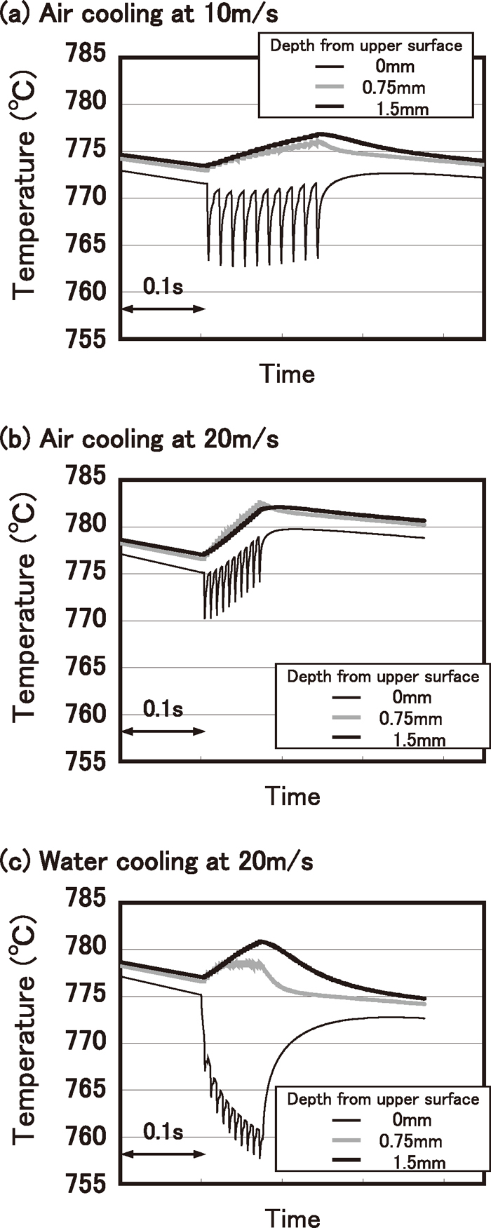
Analyzed thermal histories in industrial condition.
In Fig. 8(a), where multi-bending is applied with air cooling and the transfer speed is 10 m/s, the strip temperature decreases gradually with repetition of a thermal amplitude of 8°C at the surface, while the temperature at the center of thickness rises by 3.3°C due to multi-bending. The average temperature rise in the thickness direction is 1.8°C, and it can be said that heat generation by multi-bending is almost equal to heat loss by contact with the bending rollers and cooling by air.
Figure 8(b) shows the thermal histories during multi-bending with air cooling at the transfer speed of 20 m/s, assuming higher productivity. As the contact time between the strip and a bending roller is half of that under the conditions in Fig. 8(a), the surface temperature increases. Since the effect of thermal diffusion is small compared with heat generation by deformation, the temperature rises by 5°C at the center of thickness. During multi-bending, the temperature at the depth of 0.75 mm becomes higher than that at the center of thickness in the early stage, and this relationship continues. However, the strip temperature will exceed the appropriate range for grain refinement if this deformation is applied continuously. Therefore, it seems necessary to apply water cooling in multi-bending units or between one multi-bending unit and the next.
Figure 8(c) shows the thermal histories during multi-bending with water cooling at the transfer speed of 20 m/s. As contact with the bending rollers and water cooling are repeated intermittently, the temperature drop at the strip surface is the largest under these conditions, 15°C. However, the amplitude of the surface temperature is small, and temperature restoration during non-contact with the bending rollers is also small. The rise in temperature at the depth of 0.75 mm, which is slightly smaller than that illustrated in Fig. 8(b), begins to slow down approximately 0.04 s after the start of deformation. This is due to the fact that the strip thickness is thin, 3 mm, and as a result, the effect of thermal diffusivity appears within a short time. As the average temperature drop is small, 1.1°C, heat generation by multi-bending is almost equal to heat loss due to contact with the bending rollers and heat transfer by air cooling, which is similar to the result in Fig. 8(a). Thus, it can be considered possible to realize a multi-bending process which keeps the strip temperature in the appropriate temperature range for grain refinement when a combination of deformation and cooling is applied repeatedly, as illustrated in Figs. 8(a) and 8(c).
Figure 9 shows the change in the strip temperature distributions in the thickness direction before and after contact with a bending roller for the last pass in a total of 21 passes. The temperature drop due to contact with the bending roller is the smallest, at 3°C, in Fig. 9(c), where the transfer speed is higher and the difference between the heat transfer coefficients during contact and non-contact is smaller. This is the same result as in Fig. 8. In all cases, the temperature has risen by only approximately 1°C at the opposite non-contact surface at the end of contact.
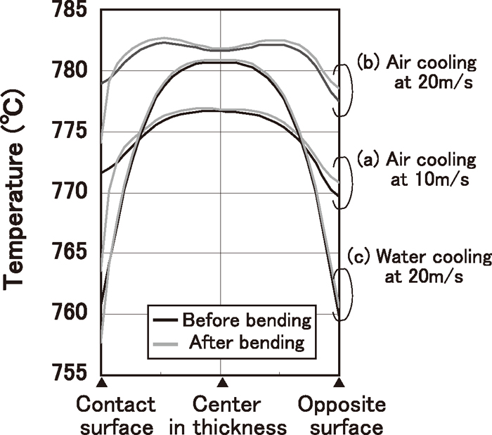
Analyzed temperature distributions in thickness direction.
Next, the shapes of the temperature distributions in the 3 cases were compared. In Fig. 9(a), a gentle parabolic curvature can be seen. In Fig. 9(b), the shape is almost flat across about half of the strip thickness around the center of thickness. The peak temperature can be seen at 0.7 mm from the center of thickness and is a maximum of 0.9°C higher than at the center. This is due to the fact that heat generation depends on the depth from the surface. A sharp temperature gradient can be seen at depths up to 0.6 mm, including at the surface.
This chapter discusses the actual thermal histories of strips in the multi-bending process in industrial operation and important items for mechanical design, after which tasks for manufacturing high quality products with uniform properties over the total length and width are introduced.
As mentioned in Chapter 3, the transfer speed in industrial production is much higher than in the laboratory test. Therefore, it is necessary to cool the strip continuously in order to cancel heat generation, which is accumulated during repeated bending, and maintain the strip temperature within the appropriate range for grain refinement. For this, it is desirable to perform multi-bending and water cooling in parallel. Realistically, however, it is quite difficult to perform water supply and drainage smoothly in the small area inter between bending rollers and apply uniform cooling across the width. Therefore, water cooling between multi-bending units might be an optional method.
In general, the width of commercial hot strip mills is more than 1.5 m. In bending rollers with small diameters of 100–150 mm, excessive roller deflection becomes a concern. This is important particularly because it is impossible to apply uniform strain and manufacture high quality products if vertical offset is not constant in the width direction.
In the thermal analysis in this research, the cooling effect of contact with the bending rollers was taken into account. However, cooling of bending rollers would be necessary in order to maintain that effect over the full length of products. When heat transfer to the bending rollers varies with time, it is necessary to change the water cooling condition of the bending rollers and strip gradually.
The temperature difference in the strip thickness direction is larger in the case of repeated bending with water cooling than with air cooling. As shown in Fig. 9(c), the temperature difference between the surface and center of thickness increases to 23°C. In the case of water cooling, the difference in the microstructure in the thickness direction becomes larger than in the case of air cooling. Therefore, in order to apply the multi-bending process to current manufacturing lines, it is important to optimize the thermal and deformational histories of strips in consideration of such characteristics. It is also necessary to design appropriate multi-bending equipment and cooling equipment which are capable of realizing the optimized condition.
As a manufacturing process for fine grained steel strips, a multi-bending process after hot rolling was proposed. A laboratory test was performed, and a fine ferrite microstructure with a minimum grain size of 1.4 μm was obtained at the strip surface. A thermal analysis assuming industrial conditions was then carried out based on the measured temperature data obtained in the laboratory test. The thermal histories of the strip and the change in the temperature distribution in the thickness direction were clarified. As results, the followings were clarified.
(1) A test sample was rolled at 800°C, accumulated strain of 2.2 was applied at surface at a temperature in the range of 770–730°C, and the strip was cooled with water. As a result, a fine ferrite microstructure with the minimum grain size of 1.4 μm was obtained. This experiment confirmed that the ferrite microstructure becomes finer with lower rolling and bending temperatures and larger accumulation of strain, and demonstrated that the multi-bending process is effective for manufacturing fine grained steel strip.
(2) During multi-bending, the strip surface temperature repeats a specific pattern with 4 steps, i.e., 1) rapid temperature drop due to contact with a bending roller, 2) temperature restoration due to thermal diffusion, 3) acceleration of temperature rise during bending without contact and 4) slowing of temperature rise due to thermal diffusion.
(3) The temperature distribution in the strip thickness direction varies in a manner depending on the transfer speed and cooling condition, namely, cooling by water or air. In the case of water cooling, the difference in the microstructure in the thickness direction becomes larger than in the case of air cooling.
(4) As industrial operations are characterized by high transfer speeds, it is necessary to cool the strip continuously in order to cancel heat generation which is accumulated during repeated bending and thus maintain the strip temperature within the appropriate range for grain refinement.