Regular Article
A Mathematical Model for Carbothermic Reduction of Dust-Carbon Composite Agglomerates
2013 年 53 巻 6 号 p. 1097-1105
詳細
2013 年 53 巻 6 号 p. 1097-1105
Recycling iron–bearing dust from steel mills has gained a considerable attention in the past two decades to recover the valuable metals in dust while improving the sustainability of steel production. As a method for extracting the metals from dust, the reduction of dust–carbon composite agglomerates using a rotary hearth furnace (RHF) has been practiced in the steel industry. The use of low–grade carbonaceous reductants, such as low–rank coal and waste plastic, is of steelmakers’ interest to further enhance the waste recycling using the RHF process. However, applying these materials as reductants has proven to be a challenging task since the impact of the released volatile gas from such reductants on reduction reactions is not predictable. In addition, the reduction kinetics of dust pellet in RHF is more complicated than the reaction behaviour of sintered ore in blast furnace due to the higher furnace temperature, faster reduction and rapid gas evolution inside the agglomerate. To predict the reaction behaviour of the dust–carbon composite in RHF, a mathematical model was developed. The model takes into consideration heat and mass transfer as well as the reduction reaction of iron and zinc oxides, gasification of carbon and release of volatiles. The simulated behaviour of a dust pellet by the proposed model provides beneficial information to promote recycling an expanded range of waste materials in the RHF process. The modelling approach and calculation results are discussed in the present paper.
Recycling iron–bearing dust from steel works has gained a significant attention from steel industry in the past two decades as a method for sustainable steel production. In addition to reducing the environmental impact of steel production, dust recycling lessens the dependence on earth’s resources. Dust is an iron oxide–bearing by–product emitted from steel making facilities, such as blast furnaces (BF), basic oxygen furnaces (BOF) and electric arc furnaces (EAF). Typical compositions of dust from various operations are shown in Table 1.1,2) More than 20 million tons of dust is estimated to have been produced around the world in 2010.3,4,5) Thus, dust is a promising secondary source for valuable metals. To recover these metals, a reduction process is required as most of the elements are oxidized in the dust.6,7)
| BF dust | BOF dust | EAF dust | |
|---|---|---|---|
| Total Fe | 40.8 | 55.4 | 17.2 |
| Total Zn | 0.05 | 1.4 | 32.2 |
| C | 20.6 | 0.0 | 1.7 |
| CaO | 7.4 | 10.6 | 5.2 |
| SiO2 | 6.1 | 2.3 | 4.0 |
A Rotary Hearth Furnace (RHF) is one of the coal–based reduction processes for dust recycling.8,9,10) In an RHF process, dust is first mixed with a carbothermic reductant and agglomerated into a pellet or a briquette. The dust–carbon composite is then fed onto the rotating hearth of the RHF and reduced into Direct Reduced Iron (DRI), provided with high furnace temperature (1250-1350°C) and strong reducing atmosphere surrounding the pellet. The percent reduction of the DRI can reach up to 90% in 15-20 minutes. The high reduction ratio enables the DRI to be utilized as a feed material for steel production facilities, including BOFs and EAFs. In addition to iron oxides, zinc oxide contained in the dust is reduced in the RHF and the produced metallic zinc is evaporated. This zinc fume is re–oxidized in a flue gas and collected in a bag filter as zinc oxide, which can be supplied as a feed stock to zinc smelters. Therefore, the dust recycling process using an RHF is proved to be a promising and viable technology, which decreases the overall consumption of raw materials for both steelmaking and zinc manufacturing by recovering secondary value of iron and zinc from dust.
As an application of the RHF process to enhance waste recycling, the utilization of low–rank coal and waste plastic as a reductant in RHF process is of steelmakers’ interest due to the depletion of high–rank coal reserve and the escalation of natural resource prices.11,12,13,14,15,16) The utilization of these low–grade carbonaceous reductants would enable the RHF process to produce metallic iron only from secondary source materials and enhance the robustness and sustainability of the process. However, the application of such material as reductant for dust has proven to be a demanding task due to their high volatile content, which is released inside the pellet at relatively low temperature.11,12,17,18,19,20) The evolved gas may react with iron oxides and may play a beneficial role in the overall reduction reactions; however, the correlation between the rapid release of volatiles and its contribution to the reactions is not fully investigated. In addition, the rapid evolution of gas increases the internal pressure and leads to the decrepitation of the pellet, which should be avoided to keep high lump ratio of the product DRI. Therefore, it is of critical importance to predict the reaction kinetics and the internal gas transfer as well as the interaction between them to utilize the low–grade carbonaceous material as a reductant for a dust pellet while avoiding its mechanical collapse.
The reaction kinetics of the dust pellet in RHF is more complicated than the reaction behaviour of a sintered ore and coke in BF. The reduction reactions of the composite proceed rapidly due to the high furnace temperature of RHF and the intense gas generation inside the pellet. In other words, the dust pellet itself behaves as a micro reactor; the kinetic and mechanical behaviour of the pellet is difficult to be predicted since it depends significantly on the chemical composition and physical properties of the pellet. Several researchers have established models for the reduction reactions of iron ore–carbon or dust–carbon composite pellets. Ueda et al.21) developed a reaction model which describes the reduction of an iron ore–carbon composite in a BF. Their model was validated against experimental results and predicts the reaction behaviour of the composite pellet. The outcome of their model has some interesting suggestions for acceleration of the pellet reduction. They estimated that the gasification of carbon was the rate controlling step of the overall reduction reaction and found that the reaction rate is significantly improved by using well–ground coke particles or carbon with low activation energy. Their simulation, however, is based on the premise that the reduction reactions take place in a blast furnace, where the governing mechanism is different from an RHF due to the lower furnace temperature. Thus, their model cannot be applied directly to the dust recycling in RHF. Sun et al.22,23,24,25) proposed a model for the reduction reaction of iron ore–carbon composite pellets in an RHF. Considering the high furnace temperature, they presumed that heat transfer plays a governing role in the overall process. Then, temperature gradients within the pellet were also taken into account. Their model was validated against experimentally measured reduction degree for various reaction periods. The model, however, does not include the reactions of hematite (Fe2O3). Hematite is often contained in dust as well as magnetite (Fe3O4) and wustite (FeO); hence, the hematite–related reactions should be included in a more comprehensive model. Also, the parameters for the carbon gasification reactions in the simulation were determined by fitting the model outputs with the experimental results. Thus, their model cannot provide the appropriate prediction when different kinds of reductants are used because the kinetic parameters for gasification strongly depend on the type of carbonaceous reductant. Itoh et al.26) established a simulation model for the simultaneous reduction of Fe2O3 and ZnO. Although their simulation includes the reduction of zinc oxide as well as hematite, they assumed the whole pellet is isothermal. Thus, their model cannot be applied to an RHF process, where the internal temperature gradient of pellet (created as a result of rapid heating regime in RHF) plays a substantial role in the reduction kinetics. Also, their model is based on CO–CO2 gas reduction and the carbon gasification inside the pellet was not taken into account.
The present research is aimed at creating a mathematical model to predict the reaction behaviour of a dust–carbon composite agglomerate in an RHF taking into consideration the internal volatile release and gas transfer as well as the reduction reactions of iron and zinc oxides in the pellet to enhance recovering valuable materials from the wide range of waste materials using the RHF process.
Several simplifying assumptions were made to express the behaviour of a pellet in the proposed mathematical model. The composite pellet is considered to be a perfect sphere and the pellet volume and diameter remain constant throughout the reaction. The pellet is divided into several imaginary concentric layers and a polar coordinate system is applied. When a pellet is placed in an RHF, the outermost layer is heated by radiation from the hot furnace atmosphere. Then, the temperature of internal layers gradually increases by heat conduction through the pellet. When a layer reaches sufficiently high temperature, corresponding reactions are initiated locally in each layer. At relatively lower temperature, volatile matter in coal or other carbonaceous reductants is released, filling the pellet pores. The released volatiles contain CO, CO2, H2, H2O and other hydrocarbons, which would initiate the reduction of oxides and the gasification of carbon. The gas species produced by these reactions are transferred through the pellet and exhausted into the furnace atmosphere. As the reduction reactions proceed, the porosity of pellet increases due to the removal of oxygen from iron oxides and the gasification of carbon, resulting in decrease of heat conduction rate.
2.2. Heat TransferAs several researchers have discussed,22,27,28,29) the large temperature gradient exists in the pellet resulting from the rapid heating regime of RHF. Consequently, heat transfer is likely to be a rate limiting step in RHF reduction of pellets. Equations (1), (2), (3) show the heat conduction equation in a polar coordinate system used in the model and the two boundary conditions applied. Taking into account the rapid change of the composition and temperature of dust–carbon agglomerates during reduction, density and specific heat in Eq. (1) are determined as functions of pellet constituents and temperature. Equation (2) describes the radiation heat conveyed from the furnace onto the pellet surface. Equation (3) corresponds to the energy conservation at the pellet centre where no heat is exchanged. The physical and chemical parameters used in these equations can be found in References.30,31) These heat transfer equations represent a dust pellet suspended in a laboratory–scale furnace, where all spherical surface of the pellet receives the same radiation heat from the furnace atmosphere to compare the model calculation outputs with the corresponding experimental results. In a real RHF, however, dust pellets are accumulated in 1.5–2.0 layers on the hearth, and not all points of the pellet surface are heated equally due to the shadow effect of other adjacent agglomerates and hearth. The heat transfer mechanism described in the proposed model can be applicable to the actual furnace by adjusting the emissivity, effective surface area and furnace temperature for heat radiation.
| (1) |
| (2) |
| (3) |
The thermal conductivities of the solid and gaseous phases of pellet are derived from Eqs. (4) and (5).32,33,34) As shown in Eq. (6), the overall effective thermal conductivity of the pellet is obtained as a function of these conductivities and the pellet porosity, which consists of three different formulas depending on the value of porosity.35) The parameters, α and β, used in the equation are given by Eq. (7). When calculating the effective thermal conductivity, heat radiation between particles inside the pellet is neglected taking into account model simplicity and analyses by Tien et al.36) and Argento et al.37) Their analyses have shown that the conduction through the metallic elements which are increased by reduction reactions at high temperature in this pellet system becomes dominating in the overall heat transfer although the contribution of the radiative effect also becomes considerable.
| (4) |
| (5) |
| (6) |
| (7) |
The major reactions taking place in a dust–carbon composite pellet are the evaporation of volatiles from coal or other carbonaceous reductants, the reduction of iron oxides and zinc oxide, and the gasification of carbon. The chemical formulae representing these reactions are shown in Reactions (8)–(19). At the initial stage of the RHF process, the reduction reactions (9)–(17) are initiated by CO and H2 gases released from the volatile contents generated by Reaction (8). Then, the reduction reactions proceed while the reducing gases are supplied by the volatiles as well as the Boudouard Reaction (18) and carbon–steam reaction (19). In addition to the reactions listed below, the reduction by solid carbon might occur. However, it is difficult to estimate the extent of this reaction and the share of the solid state reduction is minimal considering much larger contact area between gas–solid and faster diffusion. Therefore, no solid–solid reaction is taken into account in the present model. In addition, gas–gas interactions are also neglected for the sake of model simplicity.
| (8) |
| (9) |
| (10) |
| (11) |
| (12) |
| (13) |
| (14) |
| (15) |
| (16) |
| (17) |
| (18) |
| (19) |
The gas release from volatile matter is presumed to be a self–degradation reaction. Hence, the rate of volatilization reaction is considered to be proportional to the remaining amount of each volatile component, as expressed in Eq. (20). The rate constant can be derived from Eq. (21) with an Arrhenius–type dependence on temperature. The parameters required for these volatilization reactions are summarized in Table 2.
| (20) |
| (21) |
| Reactions | component of volatile matter | kV0 (s–1) | Ea (103 J·mol–1) |
|---|---|---|---|
| (9) | loosely bound CO | 583 | 86.2 |
| (9) | tightly bound CO | 742 | 100.4 |
| (9) | CO2 | 0.5 | 33.5 |
| (9) | H2 | 450 | 106.3 |
| (9) | H2O | 1.5 | 41.4 |
| (9) | CH4 | 383 | 81.2 |
| (9) | C2H4 | 383 | 81.2 |
| (9) | C3H8 | 383 | 81.2 |
| (9) | C6H6 | 125 | 66.9 |
As the reduction reactions of iron oxides are also assumed to be first–order reactions with respect to the relevant gaseous concentration, the reaction rates are obtained by Eqs. (22) and (23). The equations for the rates of carbon gasification by CO2 and H2O are described in the same manner as shown in Eqs. (24) and (25). The values of parameters used in Eqs. (22), (23), (24), (25) are listed in Table 3. The surface area, shown by Sreactant, Sproduct or Scarbon in Eqs. (22) and (24) indicates the total reactive area of each solid constituent exposed to the gas phase inside the pellet, where the solid components can react with the gases. The reactive surface area of oxide species (i.e. iron or zinc oxide) is the total surface area of its particles; thus, the area has the strong dependence on the particle size distribution. Unlike these oxides, a carbon particle itself has a very porous structure with a reaction area much larger than its spherical surface area. Therefore, in the present model, the BET surface area measured by liquid N2 adsorption is used as the reactive surface area for the carbon gasification reactions. The parameters fS and fSC in Eqs. (23) and (25) are defined as surface area correction factors (SACF), which are introduced to modify the reaction rate constant to be suitable for the present model from the published values.
| (22) |
| (23) |
| (24) |
| (25) |
| Reactions | k0 (m·s–1) | Ea (103 J·mol–1) | KE | fS, fSC |
|---|---|---|---|---|
| (9) | 2700 | 113.8 | exp(4.91 + 6235/T) | 2.3 |
| (10) | 160 | 92.0 | exp(8.384 + 2547/T) for T<848 (K) | 2.3 |
| exp(8.102 + 2065/T) for T ≥848 (K) | ||||
| (11) | 25 | 73.6 | exp(1.52 – 623/T) | 2.3 |
| (12) | 23 | 71.1 | exp(5.19 – 4685/T) | 2.3 |
| (13) | 16 | 73.6 | exp(–0.84 + 949/T) | 2.3 |
| (14) | 6.5 | 68.6 | exp(3.95 – 3931/T) | 2.3 |
| (15) | 17 | 69.4 | exp(–2.82 + 2376/T) | 2.3 |
| (16) | 30 | 63.6 | exp(1.01 – 1858/T) | 2.3 |
| (17) | 18 | 86.2 | exp(14.310 – 22871/T) | 4.0 |
| (18) | 1.87×10⁸ | 221.8 | exp(32.80 – 20766/T)/(RT) | 116.5 |
| (19) | 6.05×10⁵ | 172.7 | exp(28.61 – 16142/T)/(RT) | 116.5 |
The particle size distribution plays a critical role in determining the reactive surface area of oxide particles. In the present model, the distribution function proposed by Rosin and Rammlar is applied to represent their particle diameter distribution.40) Equation (26) describes the Rosin–Rammlar (RR) distribution, where R(x) is weight percentage of the particles with diameter under x (%–passing) and the parameters, mR and kR, determine the shape and width of the distribution. These parameters can be determined when two sets of diameter x and weight percentage R(x) are measured. Once the RR distribution function is obtained, mass–based median diameter, d50, can be derived from Eq. (27) as an indicator of the fineness of the particles.
| (26) |
| (27) |
The total surface area of all particles is of interest to determine the reaction rate of the oxide reduction. It can be obtained by Eq. (28), summing up the surface area of the particles having different diameters. The existence of fine particles dramatically increases the total area due to their large specific area. However, the fine particles in ore or dust are often spontaneously agglomerated to one another and behave as one particle. Several researchers suggested through experimental observations that it is reasonable to consider that the particles having less than 0.5 μm diameters are likely to clump together and behave as larger agglomerates.3,41,42) Thus, the surface of the smaller particles under the threshold diameter does not contribute to the reactive surface area. Consequently, the apparent minimum diameter, xmin in Eq. (28) is set as 0.5 μm. On the other hand, xmax = 10 mm is used considering that such large particles’ contribution to the total surface area is negligible.
| (28) |
BET method is widely used to determine the total reactive surface area of a carbon particle. Two major experimental options have been proposed using two different adsorption conditions: liquid nitrogen at 77 K and carbon dioxide gas at room temperature, which hereafter are referred to as SBET (N2) and SBET (CO2), respectively.20,43) Although SBET (CO2) seems to be appropriate for the present reaction model, several researchers have concluded that SBET (N2) better represents the active surface area for the carbon gasification reactions.44,45,46) The possible reason for the superiority of SBET (N2) suggested by Hurt et al.47) is that the surface of micropores (<2.0 nm) in a carbon particle, which is counted only by CO2 method, may not contribute to the gasification reactions because it is chemically less active.20) They also suggested that the catalytic elements required for the gasification reactions mainly exist on larger pores. Liu et al.46) experimentally discovered the direct correlation between gasification rate and SBET (CO2) surface area only at 1200–1300°C, and concluded that the micropores do not play an important role in reaction at lower temperature. Therefore, SBET (N2) is used for the reactive surface area of carbon particles in the proposed model.
2.3.5. Surface Area Correction Factor (SACF)The frequency factors measured in References22,32,38) were determined with a shrinking core model where the cross–sectional area of the reactant particles was considered to be the reaction front. In the present model, however, the reactive surface area is used in the rate equations as illustrated in Fig. 1. Therefore, the SACF is introduced to obtain an appropriate pre–exponential factor for the pellet model from the published data. Equation (29) shows the reaction rate equations derived from both the shrinking core model and the present model with total area included. Sf is a variable called a surface factor, which is defined in the shrinking core model. Rearranging Eq. (29) and considering the ratio of the spherical surface area of a particle to its cross–sectional area is equal to 4 (Fig. 1), the SACF, fS = k0SCM/k0, can be calculated by Eq. (30). For a coal gasification reaction, the frequency factor is usually measured in terms of the conversion ratio of coal as an apparent factor including the effect of reaction surface. Thus, the SACF for coal gasification, fSC, can be defined as the surface area of the coal sample used in the experiment measuring its gasification rate.
| (29) |
| (30) |
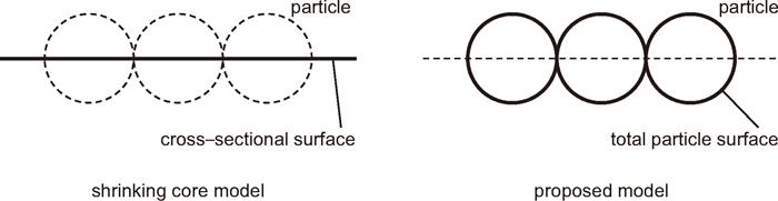
Reactive surface area.
The internal gas transfer is triggered by two factors: the concentration difference and the pressure gradient between adjacent layers in pellet. The concentration–triggered gas diffusion is described using the effective diffusion coefficient with Fick’s law, Eq. (31). On the other hand, the pressure–triggered gas flow plays more important role than the diffusive gas movement in dust reduction in an RHF.8) Noting that the reaction rates are not uniform throughout the dust pellet due to the substantial temperature gradient and also taking into account that the release of volatiles takes place at low temperature, there exists a significant internal pressure gradient within the pellet. This internal pressure curve creates the intense gas flow in the porous pellet. In the present model, a modified Hagen–Poiseuille Eq. (32)48) is applied to express this flow assuming that the pressure–driven gas flow is laminar flow considering the porous area in the pellet is sufficiently small. Arranging Eqs. (31) and (32) leads to Eq. (33), which describes the trend of the concentration of gas components in porous area of pellet. Equation (34) indicates the boundary condition at the pellet centre where no gas is transferred. Equations (35) and (36) describe the conditions of the gas exchange at the pellet surface for diffusive flow and laminar flow, respectively. Mass transfer coefficient kg between furnace and pellet surface can be determined by Frössling equation (Eq. (37)). It should be noted that Df, Scf and Ref indicate the diffusion coefficient, Schmidt number and Reynolds number with respect to the furnace gaseous atmosphere.
| (31) |
| (32) |
| (33) |
| (34) |
| (35) |
| (36) |
| (37) |
The effective diffusion coefficient inside pellet depends on the gas composition, temperature and pressure as well as the porosity of the pellet. The diffusion coefficient of a gaseous element is usually measured in a two–phase system. The coefficient follows Eq. (38) when the surrounding temperature and pressure are changed. The values of Dkl0 and mkl can be found in the published literatures.33,49,50,51) Then, the diffusion coefficient of gas component i in the real multi–phase atmosphere is derived by Eq. (39).52) Finally, the effective diffusion coefficient for the present model is determined with Eq. (40) as a function of the porous structure.48)
| (38) |
| (39) |
| (40) |
Several assumptions were made to derive Eq. (32) for the internal gas flow caused by pressure gradient. First, the pore fraction of each layer is divided into Nh imaginary straight tubes with length of Δr (thickness of each layer) and uniform diameter dc. The gas transfer within each tube is presumed to be a laminar flow. Accordingly, a modified Hagen–Poiseuille Eq. (32) is applied to determine the flow rate. The viscosity of gas in the equation can be obtained from Sutherland’s Eq. (41).53) The calculation of the number and diameter of the imaginary tubes, Nh and dc, requires additional assumptions. Presuming that all solid particles are distributed randomly and uniformly in each layer of pellet, it is reasonable to consider the same number of the tubes and particles are present from the axial direction onto the surface of the layer. This assumption leads to Eqs. (42) and (43) determining the number of tubes Nh and the diameter dc.
| (41) |
| (42) |
| (43) |
Three reduction experiments of dust pellets were simulated using the proposed model. The pellets were made with BOF dust and anthracite coal or bituminous coal. These pellet specimens contain 0.8, 4.1 and 6.1 wt% volatile matter. The properties of the pellets and calculation/experimental conditions are summarized in Table 4. The experiment was carried out using a laboratory resistance heating furnace. After the furnace interior reached the predetermined temperature, the dust–coal composite sample was inserted into the furnace core. Then, it was suspended in the middle of the furnace interior so that the reduction reactions proceeded. The furnace atmosphere was kept inert during reaction by purging nitrogen. The reactions were arrested after the prescribed retention time by quenching the pellet to ambient temperature in nitrogen atmosphere while preventing it from re–oxidation. After cooling, its chemical composition was determined.
| Parameter | Run 1 | Run 2 | Run 3 | |
|---|---|---|---|---|
| Pellet temperature* | (°C) | 25 | 25 | 25 |
| Pellet weight* | (g) | 30.0 | 30.0 | 30.0 |
| Pellet diameter* | (mm) | 29.8 | 29.8 | 29.8 |
| Pellet composition* | ||||
| Total Fe | (wt%) | 52.5 | 52.0 | 48.5 |
| Metallic Fe | (wt%) | 1.0 | 1.0 | 0.9 |
| FeO | (wt%) | 37.9 | 40.3 | 37.9 |
| Total C | (wt%) | 14.3 | 14.2 | 16.9 |
| Ash | (wt%) | 6.0 | 5.6 | 5.7 |
| Volatile matter | (wt%) | 0.8 | 4.1 | 6.1 |
| Composition of volatile matter | ||||
| CO | (wt%) | 10.0 | 17.6 | 17.6 |
| CO2 | (wt%) | 12.2 | 11.7 | 11.7 |
| H2 | (wt%) | 12.7 | 3.0 | 3.0 |
| CH4 | (wt%) | 65.1 | 67.7 | 67.7 |
| Reductant coal | ||||
| Type | – | Anthracite | Bituminous | Bituminous |
| BET surface area | (m2·g–1) | 4.6 | 228.2 | 228.2 |
| Particle size distribution** | ||||
| Mass median diameter | (μm) | 93.5 | 93.5 | 93.5 |
| mR for RR function | – | 1.08 | 1.08 | 1.08 |
| kR for RR function | (μm) | 131 | 131 | 131 |
| Emissivity of pellet surface | – | 0.85 | 0.85 | 0.85 |
| Furnace atmosphere | – | N2 100% | N2 100% | N2 100% |
| Flow rate of N2 gas | (m·s–1) | 0.1 | 0.1 | 0.1 |
| Furnace temperature | (°C) | 1250 | 1250 | 1250 |
| Retention time | (sec) | 900 | 900 | 900 |
| Δr | (mm) | 0.62 | 0.62 | 0.62 |
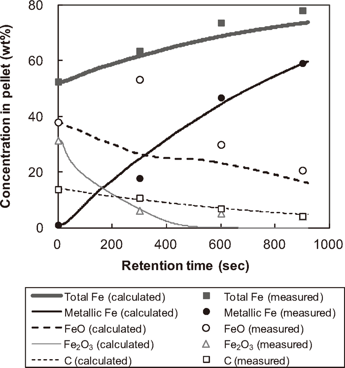
Figure 2 shows the calculated temperature trend at different positions of the pellet for Run 1. The temperature at surface reaches over 1100°C in 100 seconds while the centre temperature remains around 500°C until the end of simulation. Figure 2 clearly illustrates that the substantial temperature gradient in a pellet continues to exist throughout the reduction period. Figure 3 shows the calculated and measured concentration of total Fe, metallic Fe, FeO, Fe2O3 and residual carbon in the pellet for Run 1. Figure 3 demonstrates the pellet reduction process where the iron oxides are reduced into metallic iron consuming carbon as a reductant. The discrepancies between measured and simulated concentrations are seen at 300 seconds for all constituents. Although the reason for these differences should be further investigated, these discrepancies might be attributed to the experimental and measurement procedural matter since such a sudden concentration jump is not considered as realistic.
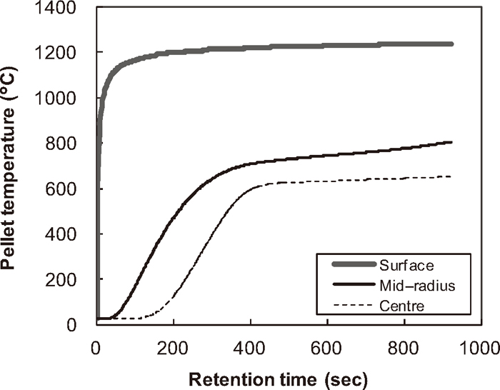
Calculated temperature.
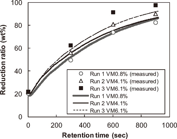
Calculated and measured reduction ratio.
In Fig. 4, the calculated iron oxide reduction ratios of the pellet samples are compared with the corresponding experimental measurements for Runs 1–3. Figure 4 indicates that the reduction rate is increased with increasing content of volatile component in the pellet. Also, the average difference between calculated and measured reduction degree is less than 5%, which is within acceptable level, noting that all kinetics constants used in the present simulations are taken from published literatures. Thus, it can be concluded that the proposed model is applicable to the reduction of dust pellet containing high volatile matter.
Calculated and measured pellet composition.
The acceleration of reduction reactions is attributed to the following two factors: the reducing gases generated from the volatile matter during heating process, and the larger BET surface area of the bituminous coal. The calculated internal pressures for Runs 1–3 close to the pellet surface, where the distance from the surface is Δr, are shown in Fig. 5. The sharp pressure increase at the beginning of the simulation implies the rapid gas release from the volatile matter and the following exhaustion of the gas out of the pellet. This gas evolution is considered to enhance the overall reduction rate as it contains reducing gases such as CO and H2. At the same time, however, the rapid rise of the internal pressure may cause the decrepitation of pellet. Therefore, the simulated results on the internal pressure and the pellet composition by the present model can be utilized to determine the optimum amount of volatile matter to be contained in a pellet for accelerating its reduction reactions while avoiding its mechanical destruction.
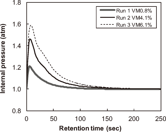
Calculated internal pressure.
In addition to the volatile matter, the larger BET surface of the bituminous coal used in Runs 2 and 3 may also contribute to the acceleration of reduction reactions because carbon gasification reactions are likely to be the rate–controlling step for the dust pellet reduction. However, due to the significantly large activation energies of these carbon gasification reactions (Ea = 221.8 and 172.7 kJ·mol–1 for Reactions (18) and (19), respectively), pellet temperature plays a more critical role than the surface area to increase the rate of gasification. For example, the exponential terms of Eq. (23) for Reaction (18) becomes 1011 times larger when the temperature increases from 200°C to 600°C, although the BET surface of bituminous coal is only 50 times larger than that of anthracite. Therefore, using high–volatile coals is more effective than using reactive coal with large BET surface to accelerate the overall rate of dust reduction reactions.
A mathematical model to predict the reaction behaviour of the dust–carbon composite agglomerate in an RHF was developed. The proposed model includes the gas transfer and the volatile release in the pellet as well as the reduction reactions of iron oxides and the gasification reaction of carbon. The calculated results by the model agree well with the corresponding experimental measurements. The simulation outputs indicate that the dust pellet reduction is accelerated by using high volatile coal as its reductant. At the same time, these simulations also show the increase of internal pressure indicating the rapid gas liberation from the volatile matter, which could lead to the physical collapse of the pellet. The simulated pellet behaviour by the proposed model provides beneficial information to determine the optimum process/operating conditions for recycling an expanded range of source materials in the RHF process.
Ck: concentration of gas component k (mol·m–3)
Ck,f: concentration of gas component k at furnace atmosphere (mol·m–3)
Ck,1: concentration of gas component k at the first layer of pellet (mol·m–3)
Cp: specific heat (J·kg–1·K–1)
d: diameter of pellet (m)
dc: average diameter of imaginary tubes (m)
d50: mass median diameter (m)
Dk: diffusion coefficient of gas component k (m2·s–1)
Dkl: diffusion coefficient of gas in two–phase system (m2·s–1)
Dkl0: standard–state diffusion coefficient of gas in two–phase system (m2·s–1)
Deff, k: effective diffusion coefficient of concentration–triggered flow of gas component k in porous media (m2·s–1)
Df: diffusion coefficient of furnace atmosphere (m2·s–1)
Ea: activation energy (J·mol–1)
fS: surface area correction factor (SACF)
fSC: surface area correction factor (SACF) for carbon gasification
Gk: laminar flow rate of gas component k (mol·s–1)
Jk: diffusive flux of gas component k (mol·m–2·s–1)
k: reaction rate constant (m·s–1)
k0: frequency factor (m·s–1)
kC: reaction rate constant for carbon gasification (m·s–1)
kC0: frequency factor for carbon gasification (m·s–1)
kV: reaction rate constant for volatilization (s–1)
kV0: frequency factor for volatilization (s–1)
k0SCM: frequency factor determined in a shrinking core model (m·s–1)
kg: mass transfer coefficient between furnace and pellet surface (m·s–1)
kR: coefficient in RRR(x) equation (m)
KE: equilibrium constant
mkl: coefficient in the equation for gas diffusion coefficient
mR: coefficient in RRR(x) equation
MVMi: molecular weight of volatile matter i (kg·mol–1)
MW: molecular weight (kg·mol–1)
n: reaction rate (mol·s–1·m–3)
nC: reaction rate of carbon gasification (mol·s–1·m–3)
nV: reaction rate of volatilization (mol·s–1)
Nh: the number of imaginary tubes
Np: the number of solid particles
Pr: total pressure at furnace atmosphere (Pa)
Pt: total pressure (Pa)
Pt,1: total pressure at the first layer of pellet (Pa)
Pk: internal partial pressure of gas component k (Pa)
ΔQ: rate of heat generated by reactions (J·s–1·m–3)
r: pellet radius (m)
R: gas constant, 8.314 (J·K–1·mol–1)
ΔRk: rate of generation of gas component k by reactions (mol·m–3·s–1)
RRR: percent passing calculated from Rosin–Rammlar equation (wt%)
Sf: surface factor used in a shrinking core model
Scross: cross–sectional area of a partcile (m2)
Stotal: total surface area (m2)
Sreactant: reaction front area of solid reactant (m2·m–3)
Sproduct: reaction front area of solid product (m2·m–3)
Scarbon: reaction front area of carbon (m2·m–3)
Su: Sutherland coefficient (K)
t: retention time (s)
T: temperature (K)
Tfurnace: temperature of furnace (K)
Tsurface: temperature of pellet surface (K)
T0: standard temperature for Sutherland equation (K)
vC: velocity of gas in furnace atmosphere (m·s–1)
V: pellet volume (m3)
Vj: volumetric fraction of solid component j in the solid portion of pellet
W: pellet weight (kg)
Wj: weight of solid component j in pellet (kg)
WVMi: weight of remaining volatile matter i in pellet (kg)
x: particle size (m)
xmin: minimum particle size to calculate the total surface area (m)
xmax: maximum particle size to calculate the total surface area (m)
Scf: Schmidt number with respect to furnace atmosphere
Shf: Sherwood number with respect to furnace atmosphere
Ref: Reynolds number with respect to furnace atmosphere
α, β: coefficients in the equation for effective thermal conductivity
ε: emissivity of pellet surface
λj: thermal conductivity of solid component j (J·s–1· m–1·K–1)
λk: thermal conductivity of gas component k (J·s–1· m–1·K–1)
λsolid: thermal conductivity of solid part of pellet (J·s–1· m–1·K–1)
λgas: thermal conductivity of gas part of pellet (J·s–1· m–1·K–1)
λeff: effective thermal conductivity (J·s–1·m–1·K–1)
μ: viscosity of gas in pellet (kg·m–1·s–1)
μf: viscosity of gas in furnace atmosphere (kg·m–1·s–1)
μk: viscosity of gas component k (kg·m–1·s–1)
μk0: standard viscosity of gas component k at temperature T0 (kg·m–1·s–1)
ρ: density of solid (kg·m–3)
ρf: density of gas in furnace atmosphere (kg·m–3)
ρj: density of solid component j (kg·m–3)
σ: Stefan–Boltzmann constant, 5.670×10⁻⁸ (J·s–1·m–2· K–4)
φ: porosity