Regular Article
A Simulation Study of Two-liquid Flow in the Taphole of the Blast Furnace
2013 年 53 巻 6 号 p. 988-994
詳細
2013 年 53 巻 6 号 p. 988-994
An undisturbed drainage of molten liquids from the hearth through the taphole(s) is a prerequisite for smooth operation, with high productivity and long campaign life of the blast furnace. Along with growing blast furnace volumes and production rates the taphole load has significantly increased. Still, the flows of molten iron and slag in the taphole have not received much attention even though several investigators have studied the multiphase drainage phenomena of the hearth. In the present paper a three-dimensional computational fluid dynamics model is developed to study the transient flow behavior of iron and slag in the taphole. The interface shape between iron and slag is simulated by utilizing the volume of fraction method. A short-term tapping process is simulated and the developing flow patterns in the taphole are illustrated. It is demonstrated that both non-stratified and stratified flows can occur at different stages of the tap, where gravity plays an important role for the evolving two-liquid flow patterns. The results of the analysis also show that the slag-iron interface and phase velocity profile are reshaped along the flow direction.
An efficient drainage is necessary for the ironmaking blast furnace (BF) since it ensures smooth operation, which is a prerequisite of high productivity and long campaign life. The draining process is driven by the in-furnace overpressure that balances the pressure drops induced by iron and slag (two-liquid) flows in the hearth and the taphole. Along with the construction of larger BFs with longer campaigns, the taphole load has significantly increased. It is therefore of importance to maintain a desired liquid flow through the taphole and to avoid tapping problems that may occur if the pressure drop in the taphole becomes excessive or shows large variations. This stresses the need to understand the drainage of the two liquids in the BF taphole.
BF drainage has been experimentally and mathematically investigated over the years.1,2,3,4,5,6,7,8,9) Most investigators have focused on the effect of various in-furnace conditions, including coke size, dead man porosity and coke-free zone on (gas, iron and slag) multiphase flow in the hearth. The two-liquid flow in the taphole, however, has received very little attention and was usually ignored or strongly simplified in these studies. Nishioka et al.5,6) developed a three-dimensional CFD model to simulate multiphase flow in the BF hearth. The shapes of the interfaces between the different phases were computed with the volume of fraction (VOF) method and the model was utilized to predict slag residual ratio and drainage rates of iron and slag for industrial BFs. The calculated drainage rates showed good agreement with the measured ones. The effect of the taphole flow was taken into account by subtracting a term from a simple expression from the total in-furnace pressure in every computational time-step. A similar treatment was later adopted by Iida et al.,7,8) who estimated the deviations of tapping time under different operation conditions. Based on the pressure balance of the BF hearth, the drainage rates of iron and slag, which are implicitly contained in the pressure drop expressions of flow in a coke particle bed (dead-man) and the taphole, were iteratively calculated. The authors assumed iron and slag to be perfectly mixed in the taphole so that average quantities, i.e., density and viscosity, could be applied. The validity of this assumption may be questioned, as large density and viscosity differences between the two phases would make it natural to assume the taphole flows to be stratified, which motivates a separate treatment of the two phases in the taphole. This treatment was adopted in the earlier work of the authors of the present paper,9) where the drainage behavior of iron and slag in BF hearth was simulated by employing a two-fluid model (TM) to assess the pressure drops induced by two-liquid flows both in hearth and the taphole.
Although the TM has been extensively validated with water-oil pipe flow systems, there is no guarantee that the information available from such cases can be applied to the slag-iron system in the BF taphole. First, the (superficial) velocity of each phase in the taphole is higher than the velocities commonly encountered in water-oil systems because of the drastic geometry ratio in BF hearth, i.e., hearth diameter/taphole size. Second, the density difference between iron and slag (≈ 4000 kg/m3) is considerably larger than that of water and oil (≈ 200 kg/m3). These two factors could restrict the applicability of TM in such a system, because they strongly influence the regime (i.e., laminar or turbulent) and pattern (stratified or non-stratified) of iron-slag flow in the taphole.
In the present work, the transient flow behavior of iron and slag in the taphole of a BF is studied by applying a VOF-based CFD model, which has been widely employed in the research11,12,13,14) of liquid-liquid pipe flow systems. However, to the best of the present authors’ knowledge, it has not been applied to analyzing the flows in the blast furnace taphole. As the focus of the work is not in the flow patterns in the hearth, the BF hearth is represented simply by a reservoir to generate inlet conditions for the taphole flows, but of limited volume to alleviate computational burden. Short-term tapping processes are simulated and the resulting taphole flow patterns during tapping, as well as the effect of gravity are illustrated with a few examples. The applicability of the TM in the taphole system is finally discussed.
The aim of the work was to study the iron-slag flow in the taphole of a medium-size BF with one taphole. In the reference furnace, the taphole is generally kept plugged for about 20–30 minutes to let the injected taphole mud solidify properly after the previous tapping operation.15) Iron often flows out first when the taphole is drilled open because the slag-iron interface has risen above the taphole during the plugging period. The interface would tilt down in the vicinity of the taphole under the drainage of iron (cf. Fig. 1(a)), thus leading to the onset of slag entrainment in the taphole.16) The two-liquid flow will last till the end of current tap cycle and iron can be “pumped” out in spite of the fact that the overall slag-iron interface is well below the taphole, due to the strong pressure gradient that develops in the viscous slag in front of the taphole (cf. Fig. 1(b)).

Schematic illustration of slag-iron interface (a) declination and (b) inclination near the taphole.
For the two-liquid taphole flow, iron and slag compete with each other for the taphole volume, and the inlet conditions, including phase flow rate and volume fraction, vary greatly during tapping. Furthermore, the inlet phase volume fraction is determined by the local interface near the taphole instead of the overall interface in the hearth. It is, therefore, very difficult to estimate appropriate inlet conditions for the two-liquid taphole flow, especially if the interface declines/inclines near the taphole (cf. Fig. 1).
2.1. Assumptions and SimplificationsIn order to shed some light on the sophisticated BF drainage process in the taphole, the following assumptions and simplifications are introduced in the model.
(1) The hearth is idealized as a finite-volume liquid reservoir (hereinafter called the hearth).
(2) The packed bed (dead-man) is absent in the finite-volume hearth.
(3) Iron is pre-filled to some distance above the taphole and only slag is supplied from the top inlet.
(4) The taphole is horizontal and cylindrical.
(5) The system is assumed to be isothermal.
The reservoir in assumption (1) generates appropriate inlet conditions for the taphole flow and can considerably alleviate the computational burden. The (admittedly strongly) simplifying assumption (2) is partly introduced because of the problems associated with the fact that the diameter of the coke particles at the taphole entrance may be of the same order as the taphole diameter, so in the real system the porous medium does not extend to the taphole entrance. Assumption (3) makes it possible to omit the third phase, gas, and the computational burden is considerably reduced by this. It should be noted that the intent of this work was not to study the end state of the tapping, where gas enters the taphole. For more details about the gas discharge from the taphole the reader is referred to He et al.17)
2.2. Governing EquationsThe transient mass and momentum equations are expressed as
| (1) |
| (2) |
| (3) |
| (4a) |
| (4b, c) |
| (5a) |
| (5b) |
| (5c) |
| Constants |
|
| Free-shear modification |
|
| Vortex-stretching modification |
with |
| Others |
|
The dimensions of the liquid reservoir were chosen in such a way that the slag-iron interface is stable except in the vicinity of the taphole, i.e., the interface is fairly horizontal at some distance from the taphole and the effect of the far-end velocity field is small. The computational domain and relative boundary conditions are shown in Fig. 2, where only half of the volume is plotted because of symmetry. The taphole length (lth) and height (zth) are also depicted in the figure. The taphole is located at a small distance above the bottom of the liquid reservoir (i.e., zth = 3dth) because this study is focused on the flow conditions near the taphole. Slag is taken into the liquid reservoir by a mass flow rate (
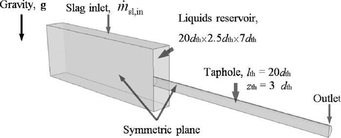
Computational domain and boundary conditions.
The CFD package FLUENT 13.0 was used to solve the equations given in this section. The geometric reconstruction scheme, which is equivalent to the piecewise-linear approach, was applied to describe the slag-iron interface. In principle, the geometric reconstruction scheme assumes that the interface between two fluids has a linear slope within each computational cell and uses this linear relation for calculation of the advection term through the cell faces. Other governing equations were discretized with second order scheme to achieve high accuracy. Furthermore, the time step, maximum iterations per time step, and relaxation factors were carefully chosen to ensure overall convergence. The parameters in the model were set as ηir = 0.007 Pa·s, ηsl = 0.4 Pa·s, ρir = 6800 kg/m3, ρsl = 2800 kg/m3,
For the initial state (t = 0 s), the (horizontal) slag-iron interface in the hearth was 7dth above the hearth bottom (cf. Fig. 2). A short-term tap was performed by iterative calculations until t = 10.0 s. The evolutions of the liquid discharge rates are plotted in Fig. 3, where slag starts flowing out at t = 1.0 s. It is observed that the flow rate of iron gradually decreases due to the loss of hydrostatic head during tapping. As a result, slag eventually replaces iron in the taphole and finally its outflow rate grows to the supply rate (
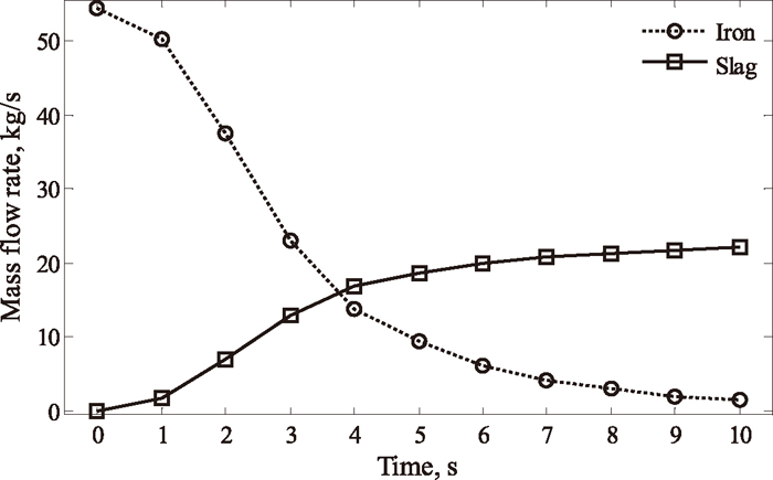
Mass flow rates of iron and slag during the short-term tapping operation.
Most of the research work on multiphase flow behavior of the BF has been carried out with three-dimensional(3D) physical cold models, because the hostile environment in BF hearth makes observations and measurements impossible. The liquid-liquid and liquid-gas interfaces, the levels of which should be identified to understand the complex drainage process, are usually filmed through a transparent symmetry plane of the equipment. This gives only 2D (cross-sectional) information about the interface shapes. This limitation can be overcome in the numerical simulations by utilizing a VOF-based CFD technique, which has been demonstrated suitable for describing the interfaces of iron and slag in the BF hearth by Nishioka et al.5,6) The authors presented the resulting 3D gas-slag and slag-iron interfaces. However, the computational cell size that is crucial for the accuracy of the VOF method was too large to accurately capture the interface shapes near the taphole in their reports, as the average cell volume was bigger than the taphole considered in the simulations.
In the present study, the grid resolution was carefully arranged, in particular near the taphole. The calculated slag-iron interfaces are shown in Fig. 4, where only half of the hearth is depicted because the interfaces on the opposite side of the taphole (i.e., negative X direction) are fairly flat. From the symmetry plane (i.e., X-Z plane), the interface tilts down to the taphole at an early stage (t = 0.2–1.0 s) of the tap because of the high flow rate of iron near the taphole. This entrainment phenomenon has been systematically investigated by Liow et al.16) By contrast, at later stages of the tap (here t = 6.0–10.0 s), when the overall iron-slag interface is well below the taphole, the interface tilts upwards to the taphole. This is consistent with observations in physical experiments reported in the literature,1,2,3,4,5,6,18) even though the dead-man is absent in the present study. Along the Y direction, perpendicular to the symmetry plane, the variation amplitude of the interface is small compared to that along the symmetry plane because the variation of the liquid velocity in the Y direction is relatively small (cf. Fig. 4).

Slag-iron interfaces during tapping.
On the basis of the simulation results, the iron-slag taphole flow can be concluded to follow two different patterns during tapping: At the intermediate stage (here t = 2.0–5.0 s) of the tap, iron and slag flow through their respective channels with no obvious phase dispersion; only small slugs and droplets are observed. This pattern is called stratified flow. For the rest of the tapping stages, the interface in the taphole is very wavy and phase dispersion commonly occurs, so the flow can be called non-stratified.
The non-stratified flow patterns at two points of time, t = 1.0 s and t = 10.0 s, are illustrated in Fig. 5, where half of the taphole is plotted. At t = 1.0 s (upper panel of Fig. 5), iron is the primary phase flowing through the taphole and slag is drained in a narrow channel above the iron, where some slugs and droplets of iron can be found (see the enlarged sections at the top of the figure). This is mainly caused by the large difference in the liquid flow rates (cf. Fig. 3) and volume fractions: The slag phase with lower flow rate and volume fraction competes for its taphole share with iron, giving rise to phase inversion19) in the slag channel. Similarly, the dispersions of slag phase in the iron channel can take place when slag becomes the primary phase at t = 10.0 s (cf. lower panel of Fig. 5). This phenomenon was also observed by Granvik,18) who conducted drainage experiments with two immiscible liquids.
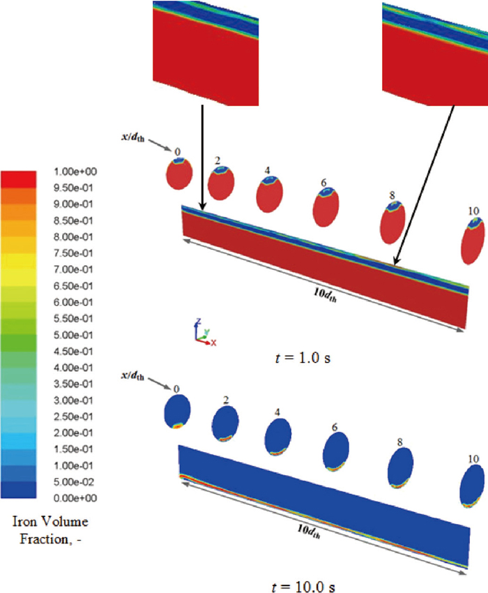
Non-stratified flows in the taphole in the early (top) and late (bottom) stages of the tapping.
The stratified flow patterns (observed for t ≈ 2.0–5.0 s) are illustrated in Fig. 6, where slag-iron interfaces are well-defined and no obvious dispersions can be observed in the taphole. This could be explained by the comparable liquid flow rates (cf. Fig. 3) and volume fractions: None of the two phases could dominate in the taphole and the large density difference damps small fluctuations at the interface. As can be seen in Fig. 6, the shape of the interface changes during tapping and the interface at each specific moment considerably reconfigures within a certain distance from the taphole entrance (x/dth = 0–10), after which the interface remains practically unchanged. This coincides with the variations of iron volume fraction along the taphole, as plotted in Fig. 7.
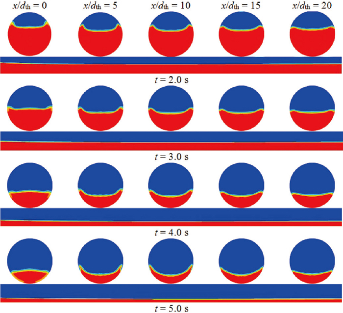
Stratified flows in the taphole.
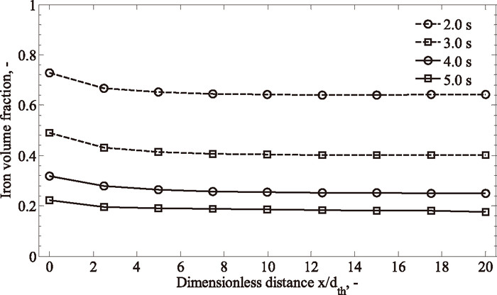
Evolutions of iron volume fraction along the taphole during tapping.
The evolutions of interface shape and iron volume fraction along the taphole (cf. Figs. 6 and 7) are caused by the development of velocity profile in the taphole. The phase velocities at three different locations (x/dth = 0, 15 and 20) along the taphole for t = 2.0 s, 3.0 s, 4.0 s and 5.0 s are demonstrated in Fig. 8, where the corresponding interface positions are also depicted (by crosses). In general, iron is pulled by slag flow due to the inlet condition in the hearth region, where slag moves faster than iron and this situation could remain as the liquids gradually approach the taphole entrance (x/dth = 0 in Fig. 8). As the liquids enter the taphole, the gravity force tends to promote phase segregation. Moreover, momentum transport is enhanced in the (narrow) taphole and near-wall boundary layers would be well established along the flow direction. As a consequence, a more uniform velocity distribution is eventually established in the downstream of the taphole (x/dth = 15, 20 in Fig. 8). In addition, the velocity profiles at these two locations almost coincide, even though minor deviations (< 2%) exist. This downstream region (x/dth = 15–20) is therefore a stable (or the fully developed) region.
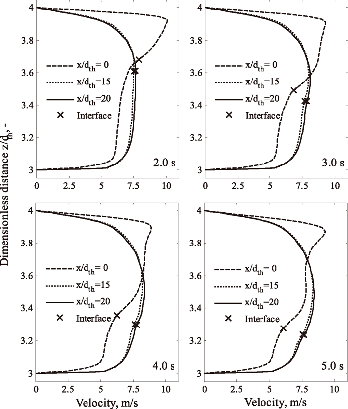
Evolution of the velocity profile in the symmetry plane during tapping.
The cases described in Figs. 6, 7, 8 will be analyzed in detail in the following subsection. The mass flow rates of slag (
| (6) |
| Case | t (s) |
|
| Res,sl × 104 | Res,ir × 106 | εir |
|---|---|---|---|---|---|---|
| 1 | 2.0 | 7.1 | 37.5 | 1.41 | 4.26 | 0.64 |
| 2 | 3.0 | 13.0 | 23.1 | 2.59 | 2.63 | 0.42 |
| 3 | 4.0 | 16.8 | 13.8 | 3.34 | 1.57 | 0.25 |
| 4 | 5.0 | 18.6 | 9.3 | 3.70 | 1.06 | 0.18 |
The Reynolds numbers of iron and slag listed in Table 2 are comparable with those of the studied industrial BF taphole. It can also be concluded that the stratified flow pattern is established in the taphole within the ratio range Res,sl/Res,ir = 0.003 – 0.035 for the industrial BF.
3.3. Detailed AnalysisUllmann et al.10) developed a modified two-liquid model (MTM) to predict the phase hold-up (i.e., volume fraction) and pressure gradient of fully developed stratified flow. The MTM has proved to be reliable as it has been validated by extensive data from experiments and engineering processes, both in laminar and turbulent regimes. Since the MTM principally solves steady-state problems, the simulated results in Table 2 are evaluated here. The schematic configuration of the MTM for the present system is shown in Fig. 9 assuming that the cross-sectional interface is flat.
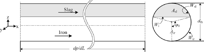
Schematic description of the stratified flow configuration.
The momentum balance equations of the MTM are
| (7a) |
| (7b) |
The geometric parameters in Fig. 9 are given by
| (8a) |
| (8b) |
| (8c, d, e) |
The shear stresses for iron and slag are calculated in a conventional manner
| (9a) |
| (9b) |
The constants in Eq. (9b) are set as C = 64 and n = 1 for Reliq < 2100; otherwise, C = 0.184 and n = 0.2. In this study, the interface shear stress depends on the relative interfacial velocity9)
| (9c) |
Equating the pressure drop terms in Eqs. 7(a), 7(b) gives
| (10) |
Given the flow rates of iron and slag (cf. Table 2), the configuration angle (φ0) determining the iron volume fraction can be calculated by iteratively solving Eq. (10). As shown in Fig. 10, the calculated iron volume fractions are in good agreement with those of the VOF-CFD model.

Comparison of iron volume fractions between the CFD and the MTM models.
In order to assess the effect of gravity on the two-liquid taphole flow, simulations were carried out omitting gravity in the model, keeping all other parameters for the simulations unchanged. Figure 11 provides a comparison between the cross-sectional interface shapes at two time instants along the taphole length. The results show that annular (t = 2.0 s) or partially annular (t = 4.0 s) flow patterns could be formed if gravity is neglected. This demonstrates the critical role of gravity in two-liquid systems, here preventing the heavy (iron) phase from dispersing into the light (slag) one and overcoming the interfacial distortion.
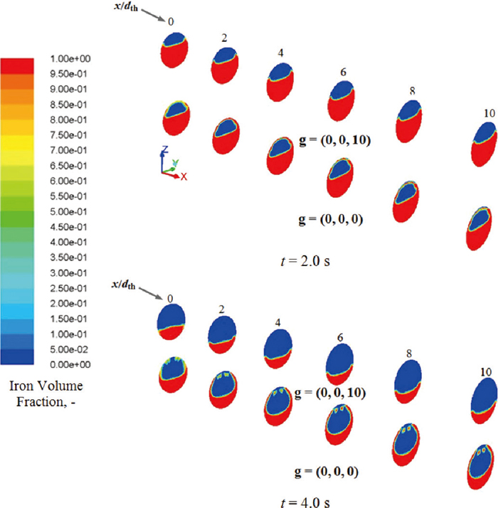
Two-liquid flow patterns in the taphole for a system without gravity.
The simultaneous flow of iron and slag in the blast furnace taphole has been studied with a transient CFD model. The interface shape was simulated with the VOF method, which has commonly been applied in flow systems of two immiscible liquids. In order to reduce the computational burden, but still obtain appropriate inlet conditions for the taphole flow, the hearth was idealized as a liquid reservoir of limited volume. Short-term tapping processes were simulated and interesting findings were obtained. These can be concluded as:
(1) Phase dispersions could occur and thus lead to non-stratified flow pattern at early or late stages of the tap. However, a stratified flow pattern is established at the intermediate stages of the tap, when phase flow rates are comparable and the Reynolds number ratio is in the range Res,sl/Res,ir = 0.003 – 0.035.
(2) The slag-iron interface and phase velocity profile are reshaped within a certain distance along the taphole and then stabilize.
(3) Gravity plays a very important role for the iron-slag taphole flow. Without the effect of gravity, annular or partially annular flow patterns can arise.
The calculated results in the stable region were evaluated with a well-established modified two-liquid model (MTM), showing good agreement in terms of iron volume fraction. Nonetheless, a number of issues still remain unexplored, including the question of how to extend the MTM to cover the reshaping process and non-stratified flow pattern in the taphole. Here, a more complicated two-liquid model from the literature could be applied. Future work will also be focused on relaxing some of the simplifying assumptions made in the model. For instance, the possibilities to model the hearth with the dead-man and gas phase will be considered. Furthermore, the taphole model will be updated to better reflect the practical counterpart, e.g., by considering different entrance shapes of the taphole and the gradual growth of the taphole diameter caused by erosion. Attempts will also be made to undertake related experimental work in laboratory scale to verify the simulated results.
The authors gratefully appreciate the language corrections and suggestions given by C-M. Wiklund of the Thermal and Flow Engineering Laboratory, Åbo Akademi University. Financial support from the Åbo Akademi foundation is also gratefully acknowledged.