Abstract
The development of the bonding phase within reduced ironsand-coal compacts was studied to investigate the reduction of ironsand-coal compacts and to understand how the oxide bonding phase develops during reduction.
Ironsand ore and sub-bituminous coal were mixed and pressed into compacts which were reduced by heating in a thermogravimetric furnace (TGA) to 1350°C under argon. The reduced compacts were characterised in terms of their composition, strength and microstructure.
The strength in the reduced compacts is brought about by slag bonding between the relict ironsand particles. Formation of a metallic network was limited, and seen only in relatively few samples. As the ironsand particles reduce, oxides surrounding the sponge iron structure form a slag. Slags from different particles then join to form a slag network between the particles. The formation of a slag and the bonding between the particles is aided by inherent silica and added lime.
Reducing the spacing between ironsand particles in the green compacts was found to be important in increasing inter-particle bonding. Increasing the coal-iron ratio in the compacts increased the spacing and decreased the bonding. Decreasing the ironsand particle size decreased the spacing between ironsand particles, and increased the bonding in the reduced compacts.
1. Introduction
There has been much interest in the use of iron ore-coal compacts in ironmaking processes as a method of improving carbon utilisation (and subsequent CO2 emission reduction) in the iron and steel industry. The principal advantage of using compacts is the fast kinetics promoted by the iron oxides and carbonaceous reductants being in intimate contact within the compact.1,2,3,4,5,6) Iron ore-carbon compacts are being utilised in new ironmaking processes such as FASTMET or ITmk3.7)
In addition to the faster reduction kinetics, another advantage of using iron ore-carbon compacts is that a wide variety of both iron sources and carbonaceous materials can be used. Compacts have been used for the reduction of different iron sources such as iron ore fines, low grade iron ores,6) plant waste3,8) or magnetite ores.9) The use of different carbon sources such as coal, coke,4) biomass10,11,12) and plastic or municipal waste13,14,15) have also been investigated. In previous studies,16,17) the authors have investigated the use of titanomagnetite ore in slowly heated compacts, finding that while the reduction of the titanomagnetite could be achieved, there were concerns with the low strength of the reduced compacts.
In this study the focus is on the use of an ironsand, a titanomagnetite ore in the form of fairly uniformly sized grains. This ore is significantly different to conventional hematite iron ores, containing high amounts of titanium and with the iron being contained in a magnetite-ulvöspinel (Fe3O4–Fe2TiO4) solid solution.18) In past studies this ore has been found to have significantly lower rates of reduction than conventional hematite or magnetite ores.19,20,21,22,23,24,25,26,27)
In previous studies16,17) with ironsand-coal compacts, the strength of the reduced compacts was found to be very low. The main binding phase was found to be a slag-like oxide phase. Low (10°C·min–1) heating and cooling rates were used during the reduction in these studies.16,17) It was thought that the low heating rates may have contributed to the low strength of the reduced compacts, and that increasing the heating and cooling rates may help improve the strength of the reduced compacts.
The aim of the study was to develop further understanding of the internal binding of reduced ironsand-coal compacts, and to investigate what effect the properties of the ironsand-coal compacts had on the bonding. To this end, ironsand-coal compacts were reduced at 1350°C while the effect of changing different parameters, such as C:Fe ratio, ironsand size and reduction time on the reduced compacts were examined. The reduced compacts were characterised in terms of their composition, strength and microstructure.
2. Experimental
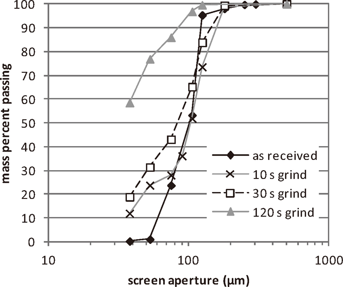
The raw materials used in this study were a titanomagnetite ore and coal. The titanomagnetite ore, as-received, was in the form of a beneficiated ironsand. The composition of the ironsand is given in Table 1. The ironsand was prepared by grinding it for varying times in a ring mill to give different particle size distributions (Fig. 1). The ironsand particle size was reported as the sieve size passing 50% by mass of the ground ironsand taken from the measured particle size distribution. The coal used in this study was a sub-bituminous coal, with the composition given in Table 2. The coal was prepared by grinding for 30 seconds in a ring mill. Limestone and corn starch were added to adjust the basicity and as a binder respectively. Both the coal and limestone passed 50% by mass through a 38 μm sieve.
Table 1. Composition of ironsand.
| component | Fe | TiO2 | Al2O3 | MgO | SiO2 | CaO | MnO | V2O3 | P |
|---|
| mass% | 59.3 | 7.87 | 3.52 | 2.8 | 1.94 | 0.43 | 0.63 | 0.48 | 0.034 |
Table 2. Composition of the coal, values in mass percent.
| as fed | moisture |
|
| mass% | 16.15 |
|
| dry | VM | ash | FC | S | P |
|
| mass% | 44.0 | 4.9 | 51.1 | 0.29 | 0.025 |
|
| coal ash | SiO2 | Al2O3 | Fe2O3 | CaO | MgO | Na2O | K2O | TiO2 | MnO | SO3 | P2O5 |
| mass% | 32.7 | 17.5 | 7.1 | 24.5 | 2.4 | 2.1 | 0.5 | 1.8 | 0.03 | 0.8 | 0.6 |
Several different compact compositions were produced to test different variables, such as the carbon to iron mass ratio (C:Fe) and ironsand particle size. The different compact mixtures used during the study are given in Table 3. The C:Fe ratio was taken as the ratio of fixed carbon from the proximate analysis of the coal to the total iron content of the ironsand.
Table 3. Mass per cent of constituents of compacts with different C:Fe ratios.
| C:Fe | 0.2 | 0.22 | 0.23 | 0.25 | 0.275 | 0.3 |
|---|
| PC | 71.04 | 70.7 | 70.5 | 67.91 | 66.45 | 65.05 |
| Coal | 19.66 | 20.5 | 21.7 | 23.50 | 25.29 | 27.01 |
| Limestone | 2.97 | 2.54 | 2.67 | 2.84 | 2.79 | 2.72 |
| Starch | 1.85 | 1.91 | 1.91 | 1.85 | 1.84 | 1.85 |
| Water | 4.47 | 4.34 | 4.24 | 3.90 | 3.63 | 3.37 |
The compacts were prepared by mixing appropriate amounts of ingredients using a high-speed mechanical mixer for approximately 60 seconds. 25 g batches were pressed at 3.4 kN (6.9 MPa) for 30 seconds in a 25 mm diameter die. This resulted in cylindrical compacts approximately 20 mm high. After pressing, the compacts were dried for at least 30 minutes in an oven at approximately 110°C before firing.
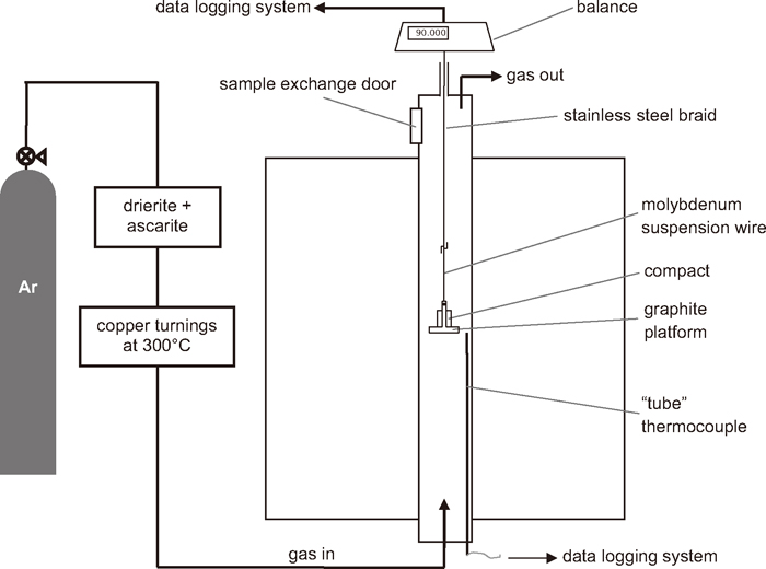
Reduction of the ironsand-coal compacts was conducted by heating the compacts under high purity argon in a thermogravimetric analysis (TGA) system. A schematic of the experimental set up is shown in Fig. 2. The initial weight of the dried compact was measured before placing it onto a graphite platform. To prevent the compacts sticking to the platform, a small amount (< 0.1 g) of graphite powder was placed between the compact and platform. The furnace was preheated to the desired temperature, and purged with high purity argon. The sample was then quickly lowered into the hot zone of the furnace. At the end of the reduction, the sample was quickly raised to the top of the furnace. A high flow rate, 5 L/min, of argon was used to help minimise reoxidation. After cooling, the weight of the reduced compact was measured and the change in its dimensions recorded. The reduced compacts were then tested for their strength and mounted for characterisation of the microstructures by SEM/EDS.
After the reduction experiments, the metallisation of the reduced compacts was calculated from the mass change. The calculated metallisation was confirmed for some samples by measurement using a wet chemical method. The mass change during reduction is due to the reaction between iron oxides and carbon, devolatisation of the coal, calcination of the limestone, and removal of the starch. In order to account for these contributions, basic assumptions were made that the volatiles in the coal and the starch were completely removed from the sample.
Metallic iron was formed from the ore by the reduction of magnetite or ulvöspinel, with the equations, which do not represent the reduction mechanism, shown in reactions 1 to 3.
|
Fe
3
O
4(s)
+
C
(s)
→
3Fe
x
O
(s)
+
CO
(g)
| (1) |
|
Fe
x
O
(s)
+
C
(s)
→
Fe
(s)
+
CO
(g)
| (2) |
|
1/
2Fe
2
TiO
4
+ C → Fe + 1/
2TiO
2
+
CO
(g)
| (3) |
The metallisation of the compacts was calculated from the mass change of the sample after reaction, using Eq. (4). Metallisation of the DRI, as opposed to a degree of reduction, gives more information about its value as a product for subsequent steelmaking processes as it takes the form of the iron into account.
|
met=
M
Fe
M
CO
(
Δ
m
exp
-
m
vol
-
m
lime
-
m
starch
-(
m
Fe,ironsand
⋅
M
CO
3
M
Fe
+
2
m
Ti
O
2
3
M
Ti
O
2
)
)
m
Fe,ironsand
+
m
Fe,ash
| (4) |
Where met is the metallisation, Δmexp is the experimental weight change, mvol is the mass of volatiles in the compact, mlime is the mass change associated with the calcination of the limestone, mstarch is the mass of starch in the compact,
m
Ti
O
2
is the total mass of TiO2 in the compact calculated from the ironsand and compact composition, mFe,ironsand is the total mass of iron in the ironsand, mFe,ash is the total mass of iron in the coal ash, and MFe, MCO and
M
Ti
O
2
are the molar masses of Fe, CO and TiO2, respectively. The experimental fractional weight change at time, t, is defined in Eq. (5).
|
experimental fractional weight change =
m
t
-
m
i
m
i
| (5) |
Where mt is the mass of the compact at time t, and mi is the initial mass of the compact.
The strength of the compacts was measured using a compression testing technique. Details of the technique are reported in the previous work.16) The cross head speed used was 1 mm·s–1. The strength of the compacts is given as the load at yield point, that is, the load at which the compacts first yielded under the compressive load. The compressive strength of reduced compacts was measured for all of the reduced compacts produced. The strengths reported are average strengths of at least two samples.
To examine the development of the microstructure during reduction, unreduced compacts, and samples reduced for 10, 11, 12, 13, 14 and 15 minutes were mounted, sectioned and characterised. The compacts were cold vacuum mounted in epoxy resin, ground and polished by hand to 1 μm, then examined using optical and electro-optical techniques. Energy dispersive spectroscopy (EDS) was used to provide semi-quantitative elemental analyses of different points within the cross-sections of the samples and elemental mapping.
3. Results and Discussion
The effects of compact composition, ironsand particle size, and time at temperature on the reduction degree and strength after reduction were measured with the microstructure of the reduced compacts being evaluated.
3.1. Reduction of Titanomagnetite-Coal Compacts
3.1.1. Change in Fractional Weight with Time
Figure 3 shows the fractional weight change and furnace temperature for reduction of compacts with different C:Fe ratios, with an ironsand size of 75 μm (ground for 30 s) at 1350°C. The temperature of the furnace decreased as the sample is introduced into the hot zone, due to the introduction of the cold sample to the furnace and the strongly endothermic evolution of volatiles from the coal. The endothermic reactions of limestone calcination and carbothermal reduction of the iron oxides also affected the temperature inside the furnace.
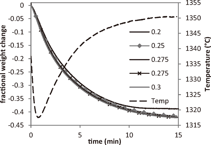
The devolatilisation of the coal is responsible for some of the fast initial weight loss from the sample. From the composition of the compacts, the volatiles make up slightly under 0.1 of the fractional mass. The decomposition of limestone and binder contribute 0.048 to the fractional mass change. Further weight loss is primarily due to the reduction reaction between the iron oxides from the ironsand and carbon from the coal. The final weight loss of these samples corresponded to a metallisation of approximately 85–90% for the majority of the compacts.
The faster heating rates of the compacts in this study lead to a significantly different shape to the weight loss curves than seen in the previous study.16,17) In that study, the compacts were heated at 10°C/min. This relatively elongated time spent at lower temperatures gave rise to a two-step weight loss curve, due to a separation between the devolatilisation and reduction processes. In the current study, the faster heating rates lead to devolatilisation and reduction occurring concurrently.
The metallisation and carbon contents of these samples are given in Table 4. In general, the metallisation of the compacts increased with increasing reduction time.
Table 4. Calculated and measured contents for samples. Ironsand size in each case was 75
μm. Metallisation measured by a wet chemical method.
| C:Fe | Reduction time (min) | Fractional Weight Change | Measured Metallisation (%) | Calculated Metallisation (%) |
|---|
| 0.20 | 10 | 0.370 | 87.5 | 86.2 |
| 0.20 | 11 | 0.379 | 88.8 | 88.9 |
| 0.20 | 13 | 0.366 | 89.8 | 85.2 |
| 0.20 | 15 | 0.367 | 90.9 | 85.4 |
| 0.20 | 15 | 0.367 | 90.1 | 85.2 |
| 0.22 | 15 | 0.386 | 90.5 | 90.2 |
| 0.23 | 15 | 0.383 | 93.5 | 89.2 |
| 0.25 | 15 | 0.394 | 96.6 | 91.8 |
| 0.25 | 15 | 0.406 | 98.4 | 95.1 |
| 0.25 | 15 | 0.406 | 92.8 | 95.3 |
(a) Observation of Products
Figure 4 shows the development of the strength of the reduced compacts with increasing reduction time. The strength of the compacts increased significantly as their residence time at the reduction temperature increased.
To follow the development of the microstructure, and to better understand the change in strength, of the reduced compacts, cross-sections of samples reduced at different times were examined using a SEM, starting with a green compact and followed by compacts reduced for 10 to 15 minutes.
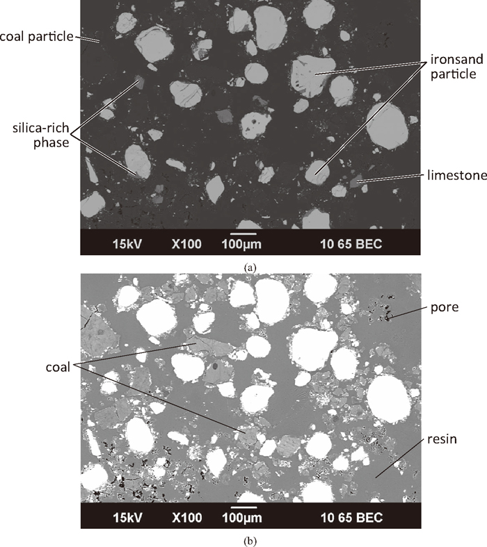
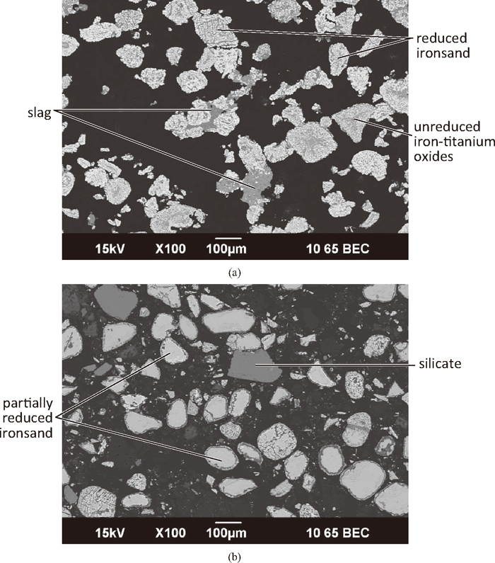
Figure 5 shows a low magnification microstructure of a green compact (C:Fe = 0.25, 75 μm ironsand). The 75 μm ironsand contained both particles of titanomagnetite (bright in Fig. 5(a)) and silica (darker). Some titanomagnetite particles contained sections of a separate phase that was silicate, which can be seen as the darker areas on the titanomagnetite particles. Separate limestone particles were noticeable in the microstructure, similar in shade to the silica particles. The distribution of the coal particles can clearly be seen in Fig. 5(b).
While the most noticeable of the ore particles are large, there were a large number of significantly smaller oxide particles. There was a large amount of free space (voids) in the compact, now filled with resin. The voids, in combination with the coal particles, keep the ironsand particles separated in the green compact.
In the reduced compacts there was a large difference between the inner and outer regions of the compacts. The exterior of the compact heated up more quickly than the interior, due to heat transfer and compounded by the endothermic reactions involved in devolatilisation of the coal, iron oxide reduction and lime calcination. In general, the outer regions were more highly reduced and had more visible bonding than the interiors of the compacts. Bonding of the reduced ironsand particles was primarily through the formation of a semi-continuous, three dimensional slag network between the particles, giving the compacts a strongly bonded outer shell. On a macroscopic scale, this outer, highly bonded shell became thicker as the reduction time increased.
It was also noted that the compacts also contracted, becoming progressively smaller as the reduction time was increased. Before reduction, the height and diameter of the compacts were close to 20 × 25 mm, while after reduction the height and diameter of the compacts were in the range of 17–20 mm and 20–23 mm respectively. This indicates that the ironsand particles were coming closer together during the reduction, likely a result of reactive or liquid phase sintering during the formation of the slag network between the ironsand particles.
Figure 6(a) shows the exterior of compacts reduced for 10 minutes. Ironsand particles were highly reduced and held together by slag. Bonding between the ironsand particles was by either the formation of a slag network incorporating several particles, or more commonly by point contact between individual particles. The oxide material was present predominantly as slag. Phases found in the slag were silicates (dark phase), CaO.TiO2 and unreduced Fe–Ti oxides (both pale). Figure 6(b) shows the intermediate and interior regions of compacts reduced for 10 minutes where ironsand particles that were not bonded and partially reduced, with significant unreacted cores. In the oxide material there was little evidence of slag formation, with separate silica-rich and limestone remnant particles.
As the reduction time increased from 11–14 minutes, the slag networks in the exterior of the compacts became further developed. Coalescence of the reduced ironsand particles occurred, with the presence of smaller reduced ironsand particles especially less evident. Large differences were seen in the intermediate regions of the compacts. As the reduction time increased, the ironsand particles became increasingly reduced, while showing increasing formation of a slag network between the particles. In the interior of the compacts, there was little evidence of bonding, although the particles became more reduced. Separation of the iron-titanium oxides in the unreacted cores of the ironsand particles into titanium enriched and titanium depleted iron oxides became evident as the reduction time increased.
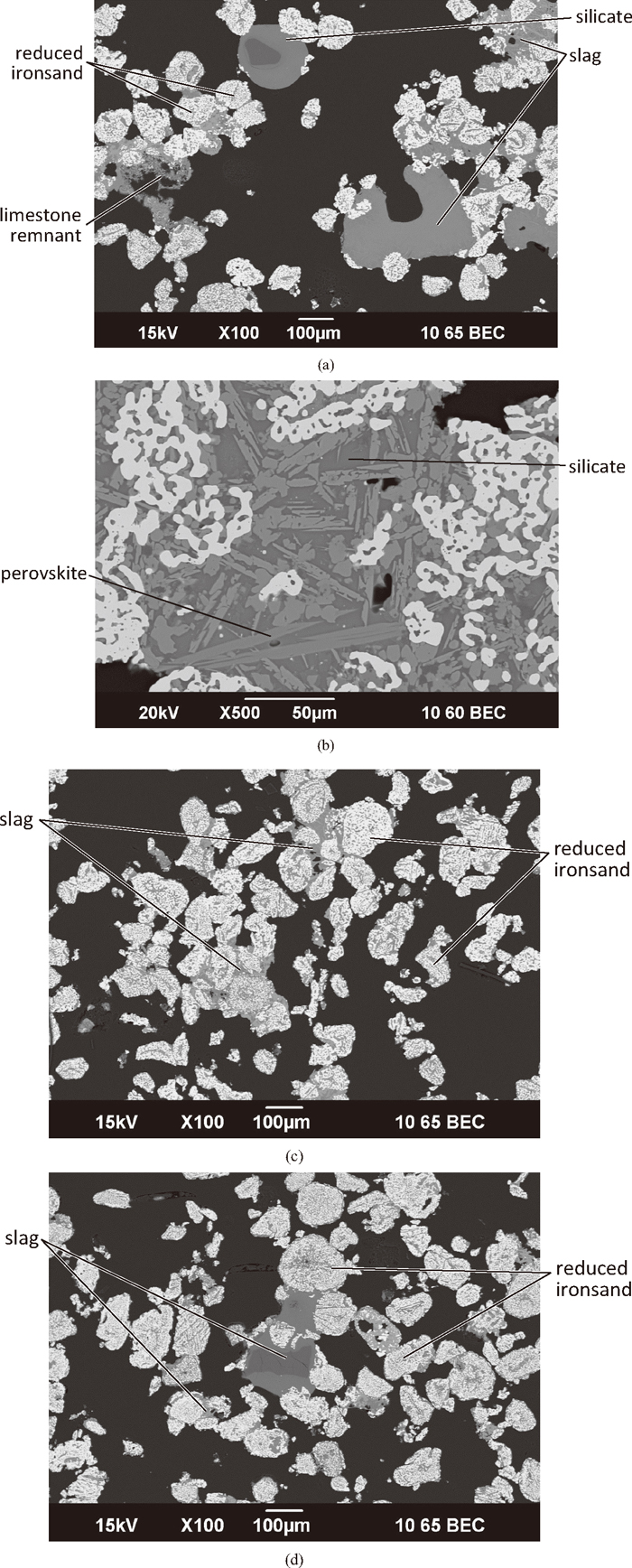
Figure 7 shows the exterior and intermediate regions of the compact after 15 minutes reduction, the longest reduction time examined. Well developed slag networks bond the ironsand particles together. Large groupings were common. In the slag phase, there appeared to be strong interaction between the different oxide sources. The darker phases were silicates with different levels of calcium oxides, also incorporating aluminium and magnesium oxides. Large amounts of perovskite, CaO.TiO2, were seen in the slag phase. In the interior of the compact, as shown in Fig. 7(d), the ironsand particles were further reduced than seen in the samples reduced for shorter times. Bonding between the particles was evident, through point contact. The oxide material in the interior of the compact was primarily as a slag, mainly associated with the ironsand gangue and unreacted Fe–Ti oxides.
The micrographs showed that bonding within the compacts was primarily due to the formation of a slag phase network between the ironsand particles together in the outer regions of the compacts. Samples that were reduced for longer periods were stronger (Fig. 4). In these samples there were more particles held together in the slag networks on microscopic level, and the strongly bonded shells becoming thicker on a macroscopic level.
(b) Analysis of Phases Formed during Reaction
The slag formed during the reduction of the compacts was not uniform, with separate areas found to be rich in silica and lime, as seen in Fig. 7(a). Increasing reduction time increased the interaction between the components of the slag. While the slag in these samples was found to contain multiple phases, the distinct separate silicate and limestone remnant initial particles (Fig. 5(a)) were no longer present. The slags in the outer regions of the compact were predominantly found to contain a darker silicate phase and paler perovskite (CaO.TiO2), shown in Fig. 7(b). The perovskite only contained small amounts of the other gangue components. The lime-titania system is a high melting point system, with perovskite melting at 1960°C.28) The perovskite present in the slags could have been solid at the temperatures encountered during reduction or precipitated from the slag as solubility criteria were exceeded during cooling.
The silicate phase had a much more complex and varied chemistry. In different samples this phase either had very few other components, or contained high amounts of lime, and was combined with the gangue components from the ironsand, such as alumina, magnesia, titania and iron oxides. Data for this complex system are not readily available in the literature.
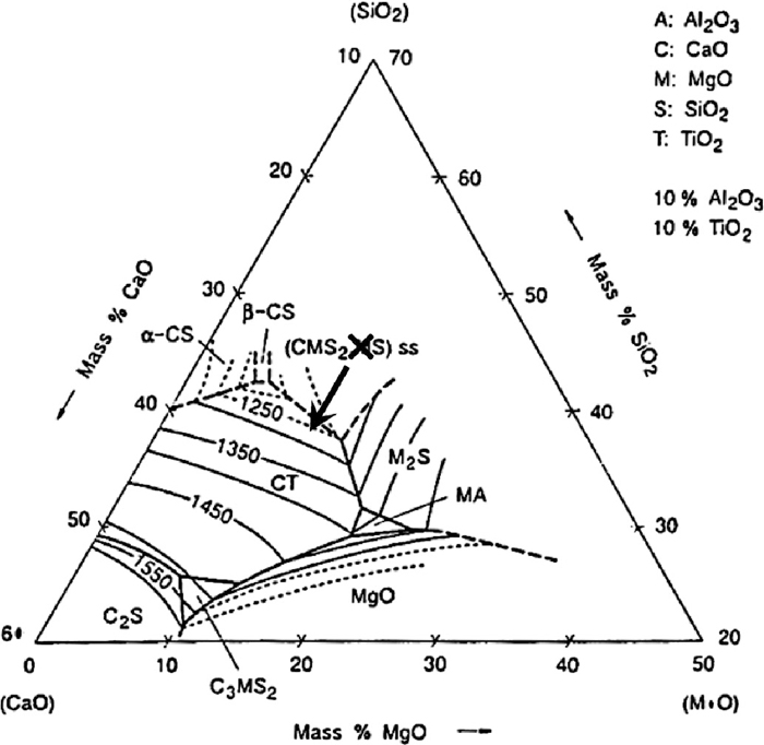
A typical composition for silicate slag was found to be approximately 10 mass% MgO, 14% Al2O3, 38% SiO2, 17% CaO, 11% TiO2 and 8% FeO, as measured by EDS. Figure 8 shows the phase diagram that is closest to the composition of the slag in the SiO2–CaO–MgO–Al2O3–TiO2 quinternary system, for the case of 10 mass% Al2O3 and 10 mass% TiO2. It can indicate the range of temperatures that liquid slag would be formed and the solid phases that are formed. The composition of the silicate slag is indicated by the cross in Fig. 8, which lies in the CaO.MgO.SiO2–MgO.SiO2 solid solution field with no liquidus temperatures indicated. However, as perovskite was formed during the reduction the overall composition of the slag was richer in both CaO and TiO2, as indicated by the arrow. This moves the slag into a region where perovskite is formed, with liquidus temperatures of 1350°C and below, indicating that at least a partially liquid slag was formed during the reduction of the compacts, agreeing with the microstructures of the reduced compacts.
(c) Change with Time during Reaction
Increasing the time of reduction can afford the time available for slag to be produced and to subsequently form bonds between the ironsand particles. Increasing the time the compacts spent at elevated temperatures would allow the separate silica in the ironsand and the added lime to interact with the gangue from the ironsand and coal to form the slag network.
Increasing the time of reduction also changed the phases present within the slag. In many of the compacts, unreduced iron oxides were found in the centre, which was often incorporated into the slag. As time passed, these iron oxides were reduced to metallic iron, with the amount of unreduced iron oxides decreased with increasing reduction time, which was seen in the microstructures of the compacts. The magnetite-titanium oxide system is a much higher melting point system than the wüstite-titanium oxide system.28) In the original magnetite-ulvöspinel solid solution, the solidus temperature is 1524°C, and the composition of the ore gives a liquidus of approximately 1550°C. However, the wüstite-titanium oxide system has much lower melting points. At the wüstite rich end of the phase diagram there is a eutectic temperature of 1312°C, well below the reduction temperatures. As the iron is progressively reduced from the oxides, the titanium oxides were seen in the microstructures to combine with the alumina and magnesia from the ore. When external silica and/or lime became part of the system, slag was formed, or the lime combined with the titanium oxides to form perovskite.
3.2. Effect of C:Fe Ratio and Ironsand Particle Size
The fractional weight change for the reduction of compacts with different C:Fe ratios with an ironsand size of 75 μm at 1350°C was shown in Fig. 3. The weight change curves for the compacts with different C:Fe ratios are similar in the cases of C:Fe = 0.25, 0.275 and 0.3. At a C:Fe ratio of 0.2, the weight loss curve showed a deviation away from the others due to this compact having not enough carbon to complete reduction. For stoichiometric reduction of the ironsand by the fixed carbon in the coal, a C:Fe ratio of at least 0.25 is required. The metallisation of the reduced ironsand-coal compacts was given in Table 4. It could be seen that the metallisation increased with increasing C:Fe ratio.
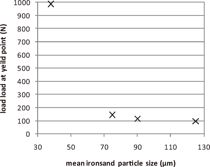
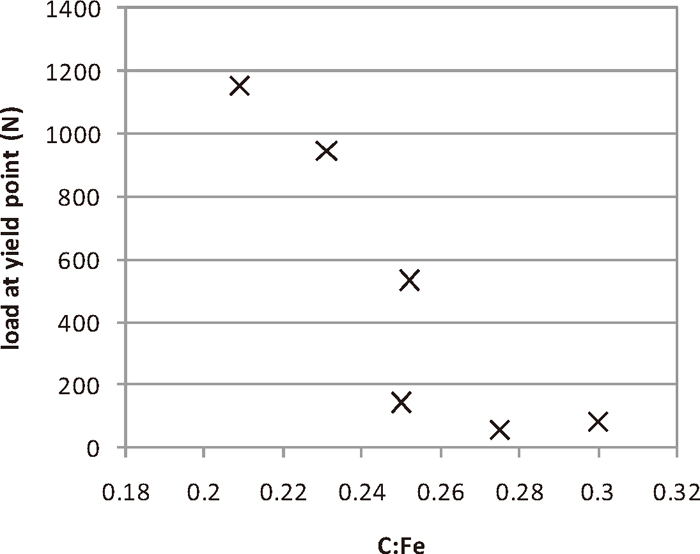
The variation of the reduced compact strength with the C:Fe ratio is shown in Fig. 9. The strength of the compacts decreased as the C:Fe ratio increases. There was a very sharp change in the strength of the compacts at a C:Fe of 0.25. The strength of compacts made with ironsand ground to different sizes is shown in Fig. 10. As the ironsand particle size decreased, the strength of the compacts increased, with a larger effect seen at the lowest mean particle sizes examined. The tipping points in the strength of the compacts, with C:Fe < 0.25 and size < 75 μm being the thresholds for the formation of strong, reduced compacts.
As the particle size had a large effect on the strength of the reduced compacts, the microstructures of green and compacts reduced for 15 minutes were examined, for as-received ironsand particle (125 μm) and 38 μm ironsand, and compared to the baseline 75 μm case. The microstructure of a green compact prepared with 125 μm ironsand is shown in Fig. 11(a). The compact consisted of large, widely spaced, ironsand particles surrounded by the coal. Magnesium and aluminium oxides were found in the titanomagnetite. Silicon oxides were found as part of the ironsand, either as separate particles, or as a distinct separate phase attached to the titanomagnetite grains. Calcium oxides were found as separate particles corresponding to the added limestone.
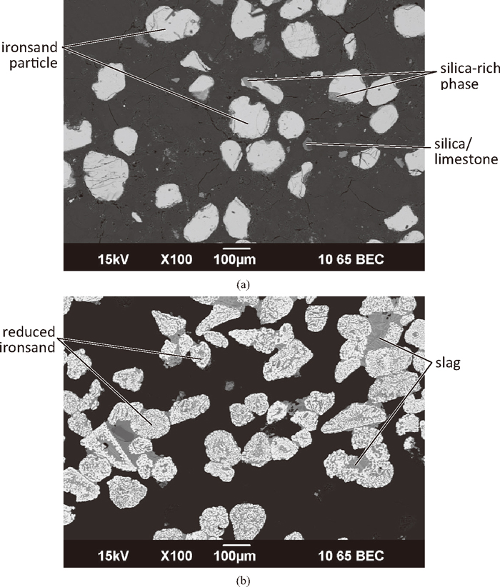
The microstructure of a reduced compact prepared with 125 μm ironsand is shown in Fig. 11(b). The exterior of the compact consisted of fully reduced ironsand particles, some of which are joined by a slag network. Particles were either joined together by a large amount of slag filling the spaces between the ironsand particles, or by a much smaller amount of slag along the adjoining edges of the particles. The paler regions are predominantly perovskite (CaO.TiO2), with some being unreduced iron-titanium oxides. These unreduced iron-titanium oxides were enriched in titanium, aluminium and magnesium compared to the original titanomagnetite, and were marginally darker in colour than the perovskite. Darker regions in the slag were silicates. In the interior of the compact, the ironsand grains were partially reduced. Evidence of limited network formation was found, with unreduced iron-titanium oxides being the main phase responsible for holding the particles together.
The microstructures from a green compact prepared with 38 μm ironsand are shown in Fig. 12(a). While there were some larger particles, the majority of the ironsand was present as fine particles which largely filled up the spaces between the coal particles. The spacing between the ironsand particles is low. As well as this, several large (in the order of 200–300 μm across) clumps of ironsand particles were present in the compact. In these clumps, the larger particles were held together by very fine ironsand. This could be due to the fine particle size creating or enhancing cohesive forces, such as magnetic, Van der Waals, or electrostatic forces between the ironsand particles.
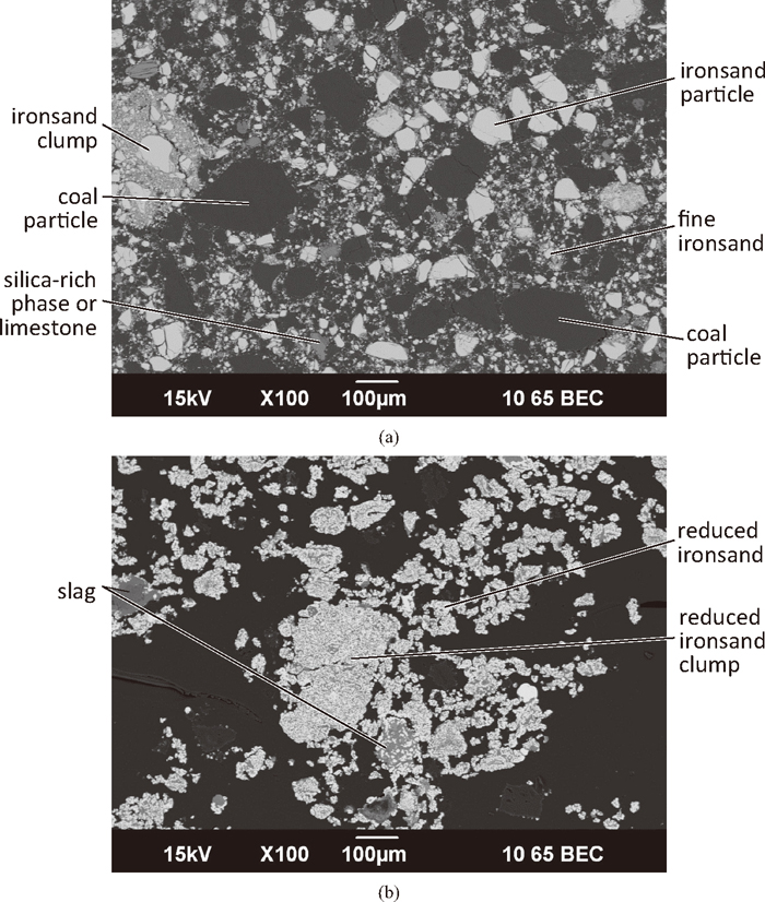
The microstructures of the reduced 38 μm compact, shown in Fig. 12(b), were significantly different to those seen in the reduced 75 μm and 125 μm compacts. There was significant bonding between the fine reduced ironsand particles, with some of the conjoined groups being up to 3–4 times larger than the largest individual particles seen in the green compact. It is possible that some of these may have been formed from the clumps of iron ore seen in the green compact. These groupings appear to be held together by the formation of both a slag and a metal network. The oxide material in the exterior of the compact mainly contained the gangue found in the ironsand, with not much penetration of the calcium or silicon into the interior of the reduced ironsand particles. There was more oxide material in the interior of the compact than the exterior. Perovskite (CaO.TiO2) and silicates containing the other gangue material were present in the slag. A phase highly enriched in titanium was seen here, as well as unreduced iron-titanium oxides.
Increasing either the C:Fe ratio and the size of the ironsand strongly decreased the strength of the reduced compacts. The microstructures of the green compacts formed from the differently ground ironsand showed large differences to each other. As the size of the ironsand decreased, the number of ironsand particles greatly increased and the spacing between the particles decreased significantly. Upon heating, the differences in the green microstructures gave rise to large differences in the microstructures of the reduced compacts. For the ironsand particles to join together they need to be close enough together for the oxides in the particles to connect and form a network. As the ironsand particle size decreases, the spacing between the ironsand particles decreases, increasing the probability of the formation more or stronger slag bonds between the particles.
The microstructures of the interiors of the finer ironsand compacts showed more bonding between the partially reduced ironsand particles. These bonds often contained unreduced iron-titanium oxides. It possible that finer particles in the interior of these compacts were reduced to lower melting point Fe2+-titanium oxides more quickly than coarser particles. These lower melting point Fe2+-titanium oxides would then be available for longer periods of time to form bonds between the particles in the interior of the compacts.
The relationship between the C:Fe ratio and the strength of the compacts can be considered along similar arguments. In the green compacts, the coal is the component with the largest volume fraction. Increasing the amount of coal in the compact would increase the separation between the ironsand particles. This would have a larger effect on the coarser ironsand particles. Some of the strongest compacts tested in this study were produced using a C:Fe ratio of 0.2. In addition to the low ironsand particle spacing, compacts with this very low C:Fe ratio do not contain enough fixed carbon to fully reduce the iron oxides giving comparatively low metallisation of these compacts. This means that there are still unreduced iron-titanium oxides in the compact after the reduction had finished, which then assisted in the formation of slag networks between the compacts.
In order to produce a reduced compact with high residual carbon levels and good strength it would be necessary to use finely ground ironsand. It is likely that the use of fine ironsand would allow the use of a higher C:Fe ratio and still display high strength after reduction.
3.3. General Mechanism of Bonding between Ironsand Particles
As the compacts are heated, the ironsand particles are reduced and metallic iron is formed in a sponge iron structure of varying coarseness. The sponge iron structure was surrounded by oxides, either the gangue components of the ironsand (alumina and magnesia) or unreduced iron-titanium oxides. If the ironsand particles were close enough together, then the oxides from different particles could touch and form a bond between the particles. As more particles were joined together by the slag, a semi-continuous, three-dimensional network of slag is formed between the reduced ironsand particles.
The slag network between the reduced ironsand particles was more fully developed at the outer regions of the compacts, forming a strong outer shell. This region of the compact would be expected to be both heated and reduced more quickly than the interior of the compacts. Consequently, the outer regions of the compacts experience both higher temperatures and the availability of the gangue minerals for longer periods during the reduction of the compacts than the interior of the compacts. These conditions are both favourable for the formation of the slag network between the ironsand particles, giving rise to the strong outer shell.
The role of the silicates and lime in the compacts was also important. Silicates were part of the ironsand, either as a separate phase within the titanomagnetite particles or as separate particles (Figs. 5 and 11(a)). As the silicates were part of the ironsand, they were in close proximity to the titanomagnetite particles. Silicates joined to the partially reduced ironsand particles and absorbed the gangue components, forming large areas of slag (Fig. 7(a)). These areas of silicate-rich slag were large enough and liquid enough to join and pull together several ironsand particles together by enveloping the particles. As these clumps were held together along a large proportion of their surfaces, these clumps are strong, and help give rise to high strength in the compact.
Lime was added as separate particles of limestone. In reduced compacts, the lime was found to be contained within the slag, combined with either silica or with titanium oxides as high melting point perovskite (CaO.TiO2). As lime is a high melting point phase, it must move in the solid state. Lime can be seen to promote bonding between the particles by forming low melting point slags with the silica. The high melting point perovskite may give some high temperature strength.
4. Conclusions
A study was undertaken to understand the reduction behaviour ironsand-coal compacts and to examine the strength of these compacts after reduction. The aim of this project was to better understand the relationship between the strength of the reduced compacts and variables such as C:Fe ratio, ironsand size, temperature and reduction time.
The reduction of the compacts was found to be carried out quickly, nearing completion after 15 minutes reduction at 1350°C. The strength of the reduced compacts increased with increasing reduction time. Increasing the reduction time increased the time available to form a slag, and for the slag to form networks between the ironsand particles.
The C:Fe ratio was found to have a large effect on the strength of the reduced compacts. Increasing the C:Fe ratio decreased the compact strength by increasing the spacing between the reduced ironsand particles, with a tipping point between strong and weak compacts at a C:Fe of 0.25. The ironsand particle size was also found to have a strong effect on the strength of the reduced compacts. Decreasing the particle size by grinding was found to increase the strength of the compacts, with a tipping point between strong and weak compacts at ironsand sizes below 75 μm. This was due to the larger number of small ironsand particles having a smaller spacing between them, allowing bonding to occur more easily.
The strength in the reduced compacts is brought about by bonding of the ironsand particles into a semi-continuous, three-dimensional slag network, primarily in the outer regions of the compact. As the ironsand particles are reduced, oxides surrounding the sponge iron structure form a slag. When the particles are close enough for the slag to touch, the particles become joined and are pulled together by liquid phase sintering. The formation of a slag and the bonding between the particles is aided by silica and lime that were not part of the original titanomagnetite. At longer reduction times there was some evidence of metallic bonding.
Acknowledgments
This work was supported by New Zealand Steel, through the University of Wollongong’s BlueScope Steel Metallurgy Centre. In addition, the authors would like to acknowledge the contributions of Lisa Wells, Kirk Foy and Harold Rogers to this study.
References
- 1) M. B. Mourão and C. Takano: Miner. Process. Extr. Metall. Rev., 24 (2003), 183.
- 2) H. Konishi, K. Ichikawa and T. Usui: ISIJ Int., 50 (2010), 386.
- 3) K. Watanabe, S. Ueda, R. Inoue and T. Ariyama: ISIJ Int., 20 (2010), 524.
- 4) S. Ueda, K. Yanagiya, K. Watanabe, T. Murakami, R. Inoue and T. Ariyama: ISIJ Int., 49 (2009), 827.
- 5) M. Kawanari, A. Matsumoto, R. Ashida and K. Miura: ISIJ Int., 51 (2011), 1227.
- 6) K. Miura, K. Miyabayashi, M. Kawanari and R. Ashida: ISIJ Int., 51 (2011), 1234.
- 7) S. Inaba and Y. Kimura: ISIJ Int., 44 (2004), 2112.
- 8) H. Tsutsumi, S. Yoshida and M. Tetsumoto: Kobelco Tech. Rev., 29 (2010), 85.
- 9) K. Ishizaki, K. Nagata and Y. Hayashi: ISIJ Int., 47 (2007), 817.
- 10) Y. Ueki, K. I. Ohno, T. Maeda, K. Nishioka and M. Shimizu: Fuel, (2010), in press.
- 11) S. Ueda, S. Watanabe, K. Yanagiya, T. Murakami, R. Inoue and T. Ariyama: ISIJ Int., 49 (2009), 1505.
- 12) Y. Ueki, A. Doi, R. Yoshiie and I. Naruse: Scanmet IV, Vol. 1, Swerea Mefos, Luleå, Sweden, (2012), 561.
- 13) K. Nishioka, T. Taniguchi, Y. Ueki, K. I. Ohno, T. Maeda and M. Shimizu: ISIJ Int., 47 (2007), 602.
- 14) T. Murakami and E. Kasai: ISIJ Int., 51 (2011), 9.
- 15) Y. Ueki, K. I. Ohno, T. Maeda, K. Nishioak and M. Shimizu: ISIJ Int., 48 (2008), 1670.
- 16) R. J. Longbottom, B. J. Monaghan, S. A. Nightingale and J. G. Mathieson: Ironmaking Steelmaking, (2012), in press.
- 17) R. J. Longbottom, B. J. Monaghan, S. A. Nightingale and J. G. Mathieson: Iron Ore 2011, AusIMM, Melbourne, Australia, (2011), 459.
- 18) J. B. Wright: New Zealand J. Geology Geophysics, 7 (1964), 424.
- 19) G. D. McAdam: Ironmaking Steelmaking, 1 (1974), 138.
- 20) G. D. McAdam, R. E. A. Dall and T. Marshall: N. Z. J. Sci., 12 (1969), 649.
- 21) G. D. McAdam, R. E. A. Dall and T. Marshall: N. Z. J. Sci., 12 (1969), 669.
- 22) E. Park: PhD Thesis, University of New South Wales, (2002).
- 23) E. Park and O. Ostrovski: Proc. of the 1st Int. Conf. on Advanced Materials Processing, Institute of Materials Engineering, Australasia, (2000), 87.
- 24) E. Park and O. Ostrovski: ISIJ Int., 43 (2003), 1316.
- 25) E. Park and O. Ostrovski: ISIJ Int., 44 (2004), 74.
- 26) E. Park and O. Ostrovski: ISIJ Int., 44 (2004), 999.
- 27) E. Park, S. B. Lee, O. Ostrovski, D. J. Min and C. H. Rhee: ISIJ Int., 44 (2004), 214.
- 28) M. Kowalski, P. J. Spencer and D. Neuschütz: Slag Atlas, ed. by Verin Duetscher Eisenhüttenleute (VDEh), Verlag Stahleisen GmbH, Düsseldorf, (1995), 70.