Abstract
In this study, a new method for swirling flow generation in submerged entry nozzle (SEN) in continuous casting of steel process has been proposed. A rotating electromagnetic field is set up around the SEN to induce swirling flow in it by the Lorentz force. And this kind of electromagnetic swirling flow in the SEN is proposed to use in square billet continuous casting of steel process. The effects of coil current intensity and nozzle structure on the flow and temperature fields in the SEN and mold are numerically simulated and verified by an electromagnetic swirling model experiment of low melting point alloy. The overall results of the study show that the magnetic flux density and the swirling flow velocity in the SEN increase with the increase of coil current intensity. The largest swirling flow velocity in the SEN can reach about 3 m/s when coil current intensity 500 A, frequency 50 Hz. The electromagnetic swirling flow in the SEN can reduce the impinging depth of the flow and increase the upward flow. An impinging flow near the mold corner can be observed. The flow field changes mentioned above result in a uniform temperature field in the mold, increase the meniscus temperature, effectively increase the temperature at the mold corner. The divergent nozzle used in this new process also reduces the impinging depth, increases the upward flow and makes the meniscus temperature increase significantly.
1. Introduction
With the development of continuous casting technology, the quality of billet has been paid more and more attention recently. It is very important in continuous casting to strictly control the cleanliness of molten steel, and to reduce the defects of billets. The control of flow pattern of molten steel in mold is one of the important means to increase casting efficiency and improve billet quality. Fundamental research by Yokoya et al.1,2,3,4,5,6) shows that, the swirling flow in submerged entry nozzle (SEN) has great effect on improving the uniformity and stability of the outlet flow of the nozzle. It can effectively reduce the meniscus fluctuation; homogenize the distributions of flow and temperature in the mold. Tsukaguchi et al.7,8) conducted commercial test of swirling flow continuous casting, in which a refractory swirling blade was installed in the SEN. The results show that in the case of round billet, the temperature of the steel at the meniscus and the equiaxed grain ratio are increased obviously.7) In the case of slab, subsurface pinholes and sliver defects are remarkably reduced.8) The effect of swirling flow on stabling the flow in the mold can match those of electromagnetic flow-control devices in mold (such as M-EMS, EMBR).8,9,10) However, a swirl blade installed in the nozzle has many demerits such as liable to cause clogging etc.,8) which limits the further application of this process. A new method for swirling flow generation in the nozzle, without the problem of clogging and easy for controlling swirling velocity, has been proposed by the authors.11) In this method, a rotating electromagnetic field is set up around the SEN to induce swirling flow in it by the Lorentz force.12) In this study, the flow and temperature fields in the SEN and square billet mold are studied numerically when this kind of electromagnetic swirling flow is generated in the SEN. And the effects of coil current intensity and nozzle structure on them are numerically examined. An electromagnetic swirling model experiment using low melting point alloy is also conducted to verify the calculation results.
2. Physical Model
Physical model of the SEN, the square billet mold and the electromagnetic swirling flow generator (EMSFG) is shown in Fig. 1. The inner diameter of the SEN is 30 mm, and the size of the square billet mold is 150 mm× 150 mm× 700 mm. Two types of the SEN (conventional and divergent) are used in the simulation.
3. Mathematical Model
A three-dimensional model of the EMSFG, the square billet mold and the SEN is used in the numerical simulation. The assumptions are made as follows. The electromagnetic properties of the fluids are uniform and isotropic. And copper plate of equivalent section is used to simulate coil. The flow is steady-state and incompressible Newtonian.
The electromagnetic field is governed by the following two equations.
where
E
→
,
B
→
,
t, ∇,
A
→
and
ϕ are electric field intensity, magnetic flux density, time, Hamilton operator, magnetic vector potential and electric scalar potential, respectively.
In this study, higher frequency of electromagnetic field than that in M-EMS can be used because the electromagnetic swirling flow generator is set up around the refractory SEN, which is non-conducting, weakly magnetic, and has little shielding effect on the electromagnetic field. And more over the Lorentz force increases as frequency increases.13) On the other hand, high frequency of the magnetic field leads to low penetration depth into the molten steel, which hinders the formation of the swirling flow. Therefore, in this study, the industrial frequency of 50 Hz is used, to meet the requirements of the Lorentz force, and no need for expensive conversion equipment of power.
In this study, the magnetic Reynolds number14) Rm=μmσvL≈ 0.045<<1, where v is the characteristic velocity of the molten steel 3 m/s, L the characteristic length of the SEN 0.015 m, μm permeability of molten steel 4π× 10–7 H/m, σ conductivity of molten steel 7.14× 10⁵ S/m. This means that the convection terms of the magnetic field can be neglected.
The shielding parameter14) Rω=μmσΩL2≈0.06<<1, where Ω=ω/p, represents for angular velocity, p number of pole pairs, in this study is 1, ω angular velocity about 314 rad/s. This indicates that the magnetic field completely penetrates into the molten steel in the SEN.
The Lorentz force components for a one-pole (p=1) magnetic field with an amplitude of B0:
|
F
z
=0
F
r
=-
1
8
B
0
2
(
ω-
v
θ
r
)
σ
2
μ
m
r
3
F
θ
=
1
2
B
0
2
(
ω-
v
θ
r
)
σr
| (3) |
where
B0 is the magnetic flux density at the molten steel surface in the SEN,
r the radius of the SEN.
The flow is governed by continuity equation and Navier-stokes equation as follows:
|
ρ
∂
v
→
∂t
=-∇p+
μ
e
Δ
v
→
+
F
→
+ρ
g
→
| (5) |
where
v
→
,
F
→
,
ρ,
μe and
g
→
represent for velocity, Lorentz force, steel density, effective viscosity and gravity acceleration, respectively. As the flow of molten steel in the nozzle and mold is turbulent, the standard two-equation
k-ε turbulence model is used for simulating, where
k and
ε represent turbulent kinetic energy and rate of energy dissipation, respectively. Turbulence model constants
Cv,
C1,
C2,
σk and σ
ε are assigned the following values 0.09, 1.44, 1.92, 1.0 and 1.3, respectively.
The temperature field is calculated by the following equation:
|
ρ
C
p
[
∂T
∂t
+∇⋅(
v
→
T)
]=∇⋅(λ∇T)
| (6) |
where
T,
λ and
Cp represent for temperature, thermal conductivity and specific heat.
The magnetic field is simulated with commercial software ANSYS EMAG. The type of analysis is three-dimensional harmonic with magnetic-node method and solid97 unit. The solving method is Full method with the real and imaginary format. Program Inc Cholesky CG is used to solve the equation. Residual criterion is 10–8. The magnetic flux vector at boundary is parallel to the exterior surface that encloses the generator. The pole number is 1, the current phase is 3, winding is a concentrated one. The flow field is calculated with commercial software FLUENT. The average velocity (vertical direction) at the inlet of the nozzle is assumed 1.3 m/s (casting speed 2.4 m/min), the inlet temperature is 1773 K. At the outlet of mold, a constant pressure and fully developed flow are assumed. At the solid walls, no-slip boundary condition is set and wall function is used.15) The inner wall temperature of the mold is 1748 K, as shown in Fig. 1. At the meniscus, slip wall boundary conditions are adopted, and is assumed as thermal insulation. Other boundary conditions are shown in Fig. 1. Least squares cell based discretization scheme is used for Gradient. Second-order upwind discretization scheme is used for turbulence and presto for pressure, quick scheme for momentum equation and the energy equation. Residual criterion is 10–3. The physical properties of the yoke and coil in the EMSFG, the molten steel and Pb-Sn-Bi alloy used in the simulation are listed in Table 1. The temperature of the yoke and coil is considered as room temperature.
Table 1. Physical properties of yoke and coil in EMSFG, molten steel and Pb–Sn–Bi alloy.
| Molten steel | Pb–Sn–Bi alloy16) | Coil | Yoke |
|---|
| Density ρ [kg/m3] | 7080 | 9620 | – | – |
| Viscosity μe [kg/(m·s)] | 0.0060 | 0.0029 | – | – |
| Conductivity σ [S/m] | 7.14 × 10⁵ | 1.11 × 10⁶ | 6.25 × 10⁷ | – |
| Relative permeability [–] | 1 | 1 | 1 | 1000 |
| Thermal conductivity λ [W/m·K] | 46.40 | – | – | – |
| Specific heat Cp [J/kg·K] | 628 | – | – | – |
The Lorentz force is firstly calculated in ANSYS EMAG, and applied as a source with UDF to calculate the flow field in FLUENT. Because the slip between revolution of electromagnetic field and molten steel isn’t considered in these two commercial softwares, artificial iteration is carried out with Eq. (3) and the magnetic flux density of corresponding coil current intensity, to achieve the Lorentz force with consideration of slip. Then the achieved Lorentz force is used to simulate the flow field.
4. Results and Discussion
4.1. Effects of Coil Current Intensity on the Magnetic Field in the SEN
Firstly, the magnetic field was studied in conventional nozzle, as shown in Fig. 1. The effects of coil current intensity on the magnetic flux density and Lorentz force are mainly investigated. The distribution of magnetic flux density on cross section of z=0 with different coil current intensities is shown in Fig. 2. With the increase of coil current intensity, the magnetic flux density in the SEN increases accordingly. The magnetic flux density in the center of the EMSFG is about 0.6 T with coil current intensity 500 A, frequency 50 Hz.
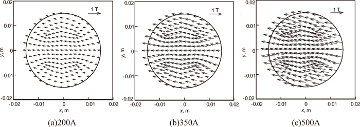
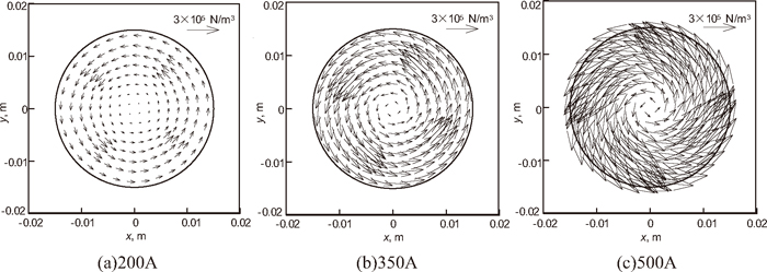
Figure 3 gives the distribution of Lorentz force on cross section of z=0 with different coil current intensities. As can be seen in this figure, the Lorentz force in the center of the EMSFG increases as coil current intensity increases. When coil current intensity is 500 A, frequency is 50 Hz, the largest time-average Lorentz force is about 5.9 × 10⁵ N/m3. In the same conditions, the Lorentz force calculated by the theory formula13) of Spitzer
F
¯
θ
=
1
2
B
0
2
ωσr
is about 6.1 × 10⁵ N/m3, where B0 is about 0.6 T, ω is 100π rad/s, σ is 7.14 × 10⁵ S/m, r is 0.015 m. The magnitude order agrees well.
4.2. Effects of Coil Current Intensity on the Flow and Temperature Fields in the SEN and Mold
The electromagnetic force is applied as a source to calculate the flow field in FLUENT, the SEN used in this simulation is also conventional nozzle. Figure 4 shows the flow field in cross section of z=0 in the SEN with different coil current intensities. In the case of 0 A, there is little horizontal velocity component. With the increase of coil current intensity, the swirling velocity increases. The largest tangential velocity can reach the order of 3 m/s with coil current intensity 500 A.
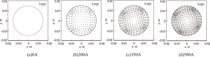
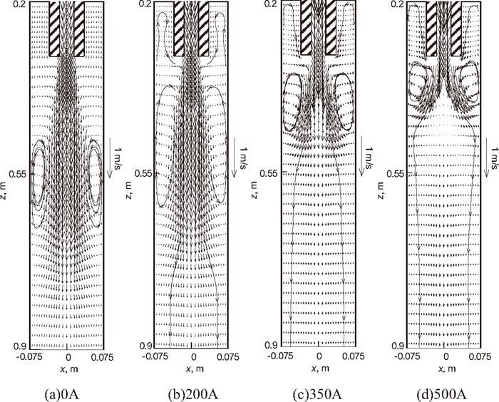
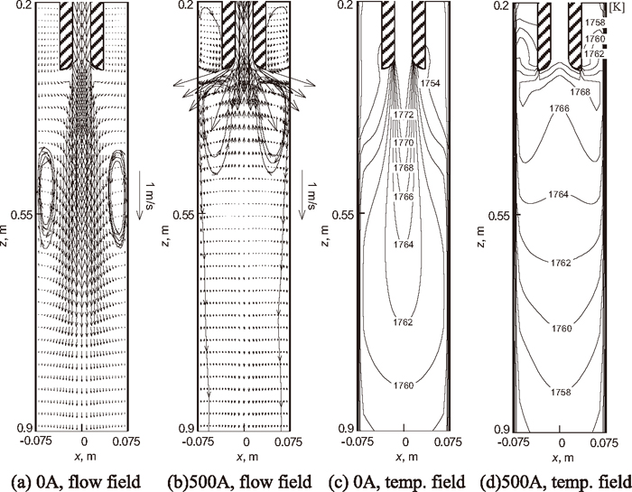
Figure 5 shows the flow field in the vertical section of the mold with different coil current intensities. Owing to the electromagnetic swirl in the SEN, the stream of the outlet flow from the nozzle becomes larger, the impinging depth of the flow becomes less. When the strength of the swirling is enhanced to a certain degree (as shown in Fig. 5(c)), the outlet flow is not concentrated down, but obviously spread downward. Furthermore, the upward flow velocity in the mold above the SEN becomes larger. It is helpful for enhancing the floating of the inclusions and improving the meniscus temperature.
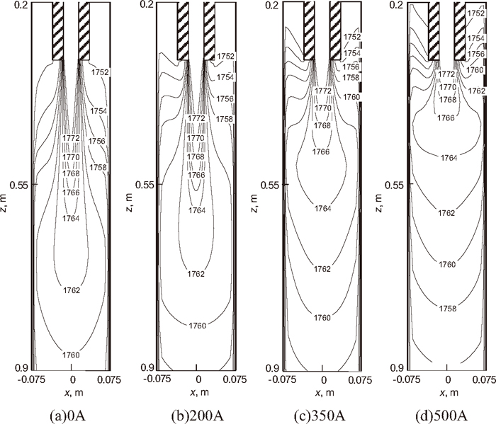
The temperature field in the vertical section of the mold with different coil current intensities is shown in Fig. 6. With the increase of coil current intensity, the high temperature zone shifts up, the temperature gradient in the mold becomes less generally, and the meniscus temperature increases.
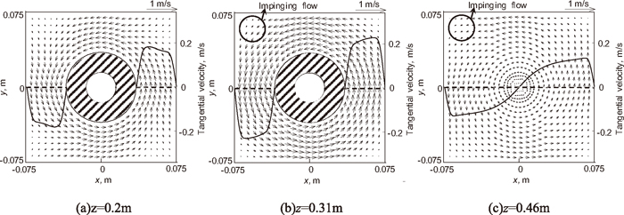
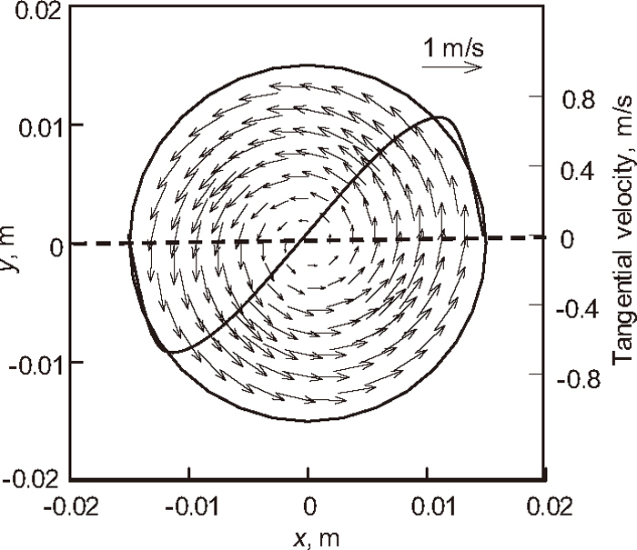
The flow field in different cross sections of the mold with 500 A electromagnetic swirling is shown in Fig. 7. (In the case of 0 A, because there is little horizontal velocity component, we don’t show it in detail here.) The tangential velocity components on line (y=0) on these cross sections are also shown in the figure with solid line. As a result of no-slip boundary conditions, the velocity of the molten steel is 0 when it reaches the mold wall or the SEN wall. It demonstrates that a swirling flow also induced in the mold by the swirling flow downward from the SEN, not only in the position below the nozzle outlet (z=0.46) but also in the vicinity of the meniscus (z=0.2). An impinging flow near the mold corner can be observed which is able to change heat and mass transfer there.
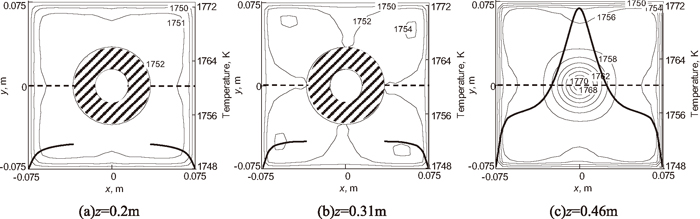
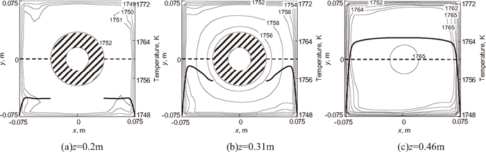
The temperature field in different cross sections of the mold with and without 500 A electromagnetic swirling together with the temperature distribution on lines (y=0) in the corresponding cross sections, are given in Figs. 8 and 9, respectively. Since we only give the temperature in the mold, so the temperature curves in these Figs. (a) and (b) are not continuous in region of the nozzle. Compared with that without electromagnetic swirling, the temperature distribution is more uniform on the cross sections of the mold. The temperature of molten steel increases obviously in the vicinity of the nozzle outlet and the meniscus temperature increases also. Owing to the impinging flow at the mold corner, the temperature at the corner increases significantly.
In the above sections, the flow and temperature fields in different sections are analyzed to investigate the regularity of the effect of coil current intensity on the flow and temperature fields in the SEN and mold. We find that the electromagnetic swirling in the SEN can drive molten steel to rotate in the mold, it is helpful to uniform the flow and temperature fields in the mold. In order to further explain the effect of electromagnetic swirling, we give the 3D flow field in the SEN and mold with and without 500 A electromagnetic swirling, the results are shown in Fig. 10. In Figs. 10(a) and 10(b), the conventional nozzle is used, while the divergent nozzle is used in Fig. 10(c). The effects of the nozzle structure on the flow and temperature fields will be discussed in next section. The figure also shows the distributions of the tangential (dashed line) and axial (solid line) velocities in the vertical section in the circled area. Comparing Figs. 10(a) with 10(b), it is clear that the swirling flow of the molten steel in the SEN can be induced by the EMSFG. When the molten steel enters into the EMSFG, the flow starts swirling obviously and the tangential velocity becomes lager with the steel falls down until the center of the EMSFG in height (z=0). After passing the center in height, the tangential velocity decreases with the falling of the steel because the Lorenz force becomes less than the viscous dissipation. At the outlet of the nozzle, the tangential velocity is about 1.5 m/s. It induces the swirling flow in the mold. With the effect of the swirling flow in the nozzle, the distribution of axial velocity component in the nozzle changes. The axial velocity near the wall of the SEN increases, while the axial velocity in the center reduces. Affected by this flow field in the SEN, at the nozzle outlet the molten steel is not concentrated down into the mold, but scattered around. Therefore, the stream of outflow becomes larger, the impinging depth of the flow becomes less. These results coincide with the earlier conclusions obtained.
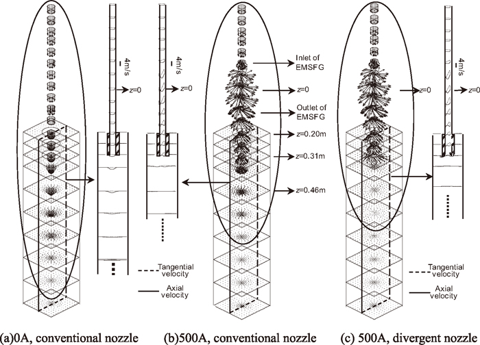
In this section, we mainly discuss the effect of the SEN structure changes on the flow and temperature fields with 500 A electromagnetic swirling. Firstly, we give the 3D flow field to visually observe the changes of the flow field in the SEN, the results are shown in Figs. 10(b) and 10(c). In the same condition (500 A, 50 Hz), comparing the simulation results both in divergent and conventional nozzles, the distributions of tangential and axial velocity component change little inside the nozzle. Therefore we can say, the structure changes at the nozzle outlet have little effect on the flow field in the SEN (except for the flow field at the nozzle outlet, the molten steel at the nozzle outlet diverges more largely in divergent nozzle). However, the flow field in the mold changes greatly, the impinging depth of the flow becomes less, and the distribution of the flow field is more uniform on each cross section below the nozzle. Therefore, we give the changes of the flow and temperature fields in the mold in divergent nozzle, the results are as follows.
The flow and temperature fields in vertical section of the mold with and without 500 A swirling flow in the divergent nozzle are given in Fig. 11. The flow and temperature fields in vertical section of the mold in the conventional nozzle are shown in Figs. 5 and 6, respectively. When there is no swirling flow in the SEN, the flow fields in mold in the conventional nozzle and the divergent nozzle are similar, as shown in Figs. 5(a) and 11(a), respectively. However, in 500 A swirling flow case (as shown in Figs. 5(d) and 11(b)), the flow field in mold changes greatly. Using divergent nozzle, the molten steel with swirl in the nozzle flows along the curved wall through the effect of centrifugal force. This causes the negative pressure to be suppressed, the stream of bulk flow diverges more widely. When the molten steel flows into the mold, it doesn’t flow down in the middle, it flows down along the wall and up in the middle below the nozzle. Comparing Figs. 6(d) with 11(d), the flow field mentioned above results in the corresponding changes in the temperature field. When using the divergent nozzle, the high temperature zone in the mold shifts up obviously, the temperature gradient in the mold becomes less generally, the meniscus temperature increases significantly.
5. Experimental Results
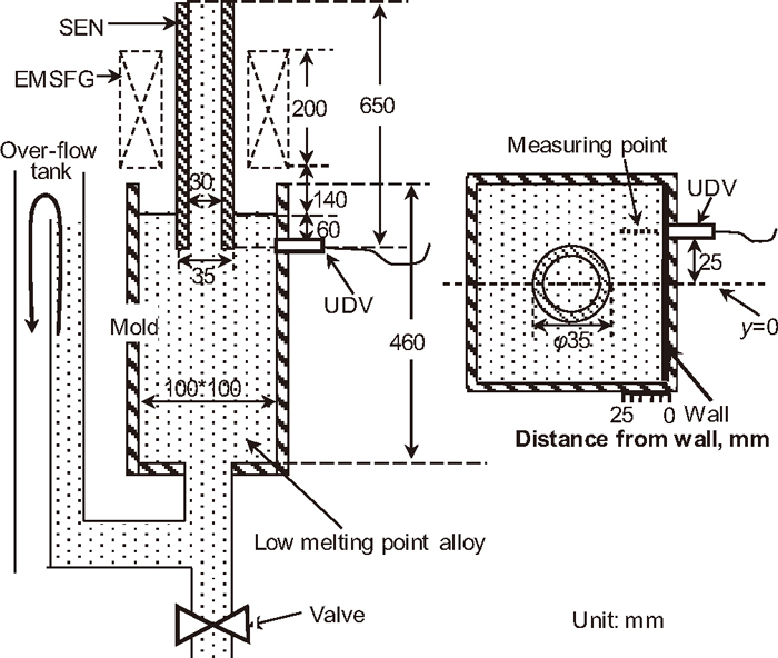
In order to validate the numerical simulation results, the electromagnetic swirling flow model experiment is conducted with low melting point alloy (30%Pb-20%Sn-50%Bi, wt% melt point 90°C) whose physical property16) (as shown in Table 1) is similar with that of molten steel. The schematic view of the electromagnetic swirling flow experiment is shown in Fig. 12. The size of the SEN and mold used in the experiment are 650 mm (height)× 30 mm (inner diameter) × 35 mm (outer diameter) and 460 mm (height)× 100 mm (width)× 100 mm (width). The immersion depth of the nozzle is 60 mm. In the experiment, the temperature of molten alloy is controlled to be 120°C, the vertical average velocity of alloy in the nozzle to be 1.5 m/s. The level of the free surface in the mold is maintained by an over-flow tank. Due to the limitations of the apparatus, the frequency of the magnetic field used in this experiment is 28 Hz. The magnetic flux density in the center of the generator in height is measured by a teslameter, as 0.22 T. Since Ultrasonic doppler velocimeters (UDV) has been successfully used in measuring the velocity of low melting point alloy in model experiment of the continuous casting process of steel,17) and it is also successfully used to measure the velocity of Pb–Sn–Bi alloy by the authors.18) In this study, the UDV is used to measure the velocity of the alloy. The UDV transducer is placed at the height of nozzle outlet to measure the horizontal velocity of the alloy, as shown in Fig. 12. The measured velocity direction is parallel to the line (y=0). The frequency of the transducer is 2 MHz.
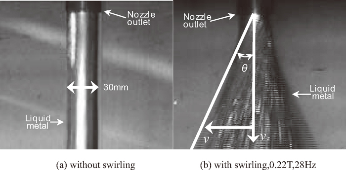
Firstly, the electromagnetic swirling flow model experiment is conducted without mold to observe the swirling flow pattern at the nozzle outlet by a high speed camera. The photos of flow pattern with and without electromagnetic swirling are shown in Figs. 13(a) and 13(b), respectively. The divergent angle θ of the alloy at the nozzle outlet is measured for estimating the swirling velocity. In the case of no swirling flow, the divergent angle of the alloy at the nozzle outlet is so small that be negligible. With swirling flow, the divergent angle θ of the alloy at the nozzle outlet is measured as 25°. And the vertical velocity is 1.5 m/s. So the maximum swirling velocity at the nozzle outlet can be decided with the help of formula
tanθ=
v
v
z
, where v is the maximum swirling velocity, vz is the vertical velocity as 1.5 m/s, θ is the divergent angle as 25°. So the maximum swirling velocity v at the nozzle outlet is about 0.7 m/s in this experiment. With the experimental parameters and physical properties of the alloy (as shown in Table 1), the flow field in this model is simulated. The flow field on the cross section of the nozzle outlet is shown in Fig. 14. The maximum swirling velocity at the nozzle outlet is about 0.69 m/s, in agreement with that in the experiment.
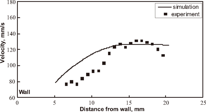
Secondly, the electromagnetic swirling flow model experiment is conducted with the mold. The velocity component of the alloy at the measuring point is measured by the UDV. The direction of the velocity component is parallel to the line y=0. In order to show the location of the measuring points clearly, the measuring points are marked in the schematic view of the electromagnetic swirling flow experiment (Fig. 12), and the horizontal axes is also shown in it. And this velocity component at the measuring point is also read from the simulation results. The measured and simulated velocity in the mold is shown in Fig. 15. In Fig. 15, the horizontal axes represents the distance of the measuring point from the mold wall, the vertical axes represents the velocity component of the alloy at the measuring point whose direction is parallel to the line (y=0). As can be seen from the experiment and simulation results in Fig. 15, the largest velocity at the measuring point is about 130 mm/s, also at this measuring point the simulation result is about 125 mm/s, in agreement with that in the experiment, and the trend of simulation results is consistent with that of experimental results. It validates the simulation method.
6. Conclusions
In this study, the electromagnetic swirling flow is applied in the SEN in square billet continuous casting of steel. The effects of coil current intensity and nozzle structure on the flow and temperature fields both in the SEN and in the mold are numerically simulated and verified by the electromagnetic swirling model experiment using low melting point alloy. The EMSFG can effectively induce swirling flow of molten steel in the SEN, which consequently greatly improves the flow and temperature fields in the mold. The following results are obtained:
(1) With the increase of coil current intensity, the magnetic flux density and the swirling flow velocity in the SEN increases. The largest swirling flow velocity in the SEN can reach about 3 m/s in coil current intensity 500 A, frequency 50 Hz.
(2) The electromagnetic swirling flow downward from the SEN can reduce the impinging depth of the flow and increase the upward flow. An impinging flow near the mold corner can be observed. The flow field changes mentioned above result in a uniform temperature field in the mold, increase the meniscus temperature, effectively increase the temperature at the mold corner.
(3) The divergent nozzle reduces the impinging depth and increases upward flow, increases the meniscus temperature significantly, compared with the conventional nozzle.
Acknowledgments
This study is financially supported by the “111 project” (B07015) and the Fundamental Research Funds for The Central Universities (N100409010), Project for Key Laboratory of Liaoning Province (LS2010065).
References
- 1) S. Yokoya, R. Westoff, Y. Asako, S. Hara and J. Szekely: ISIJ Int., 34 (1994), 889.
- 2) S. Yokoya, S. Takagi, M. Iguchi, Y. Asako, R. Westoff and S. Har: ISIJ Int., 38 (1998), 827.
- 3) S. Yokoya, S. Takagi, M. Iguchi, K. Marukawa, W. Yasugaira and S. Hara: ISIJ Int., 40 (2000), 584.
- 4) S. Yokoya, P. G. Jönsson, K. Tada, S. Takagi and M. Iguchi: Scand. J. Metall., 33 (2004), 22.
- 5) S. Kholmatov, S. Takagi, L. Jonsson, P. Jönsson and S. Yokoya: ISIJ Int., 47 (2007), 80.
- 6) Y. Tsukaguchi, M. Kawamoto, H. Hayashi, S. Furuhashi, S. Yokoya, S. Takagi and K. Marukawa: The 10th Sino-Japan Conf. on Steel and Iron, JISF, Tokyo, (2004), 191.
- 7) Y. Tsukaguchi, H. Hayashi, S. Yokoya, T. Tanaka and S. Hara: Tetsu-to-Hagané, 93 (2007), 575.
- 8) Y. Tsukaguchi, H. Nayashi, H. Kurimoto, S. Yokoya, K. Marukawa and T. Tanaka: Tetsu-to-Hagané, 95 (2009), 33.
- 9) A. Idogawa, Y. Kitano and H. Tozawa: Kawasaki Steel Giho, 28 (1996), No. 1, 46.
- 10) J. Kubota, N. Kubo, M. Suzuki, T. Ishii, R. Nishimachi and N. Aramaki: Tetsu-to-Hagané, 86 (2000), 271.
- 11) J. C. He, K. Marukawa and Z. J. Su: CN Pat, 200510047290.6, (2005).
- 12) Z. J. Su, D. W. Li, L. W. Sun, K. Marukawa and J. C. He: Acta Metall. Sin., 46 (2010), 479.
- 13) K.-H. Spitzer, M. Dubke and K. Schwerdtfeger: Metall. Trans., 17B (1986), 119.
- 14) R. Moreau: Magnetohydrodynamics, Kluwer Academic Publishers, Dordrecht/Boston/ London, (1990), 240.
- 15) B. G. Thomas, L. J. Mika and F. M. Najjar: Metal. Trans. B, 21B (1990), 387.
- 16) Y. Yoneyama, E. Takeuchi and K. Matsu: Seitetsu Kenkyu, 335 (1989), 26.
- 17) K. Timmel, S. Eckert, G. Gerbeth, F. Stefani and T. Wondeak: ISIJ Int., 50 (2010), 1134.
- 18) Y. H. Li, Z. J. Su and J. C. He: J. Iron Steel Res., Int., 17 (2010), 10.