Note
Mechanism of Grain Boundary Embrittlement in Fe–Ni–S Alloys
2013 年 53 巻 7 号 p. 1289-1291
詳細
2013 年 53 巻 7 号 p. 1289-1291
The hot forming of Fe–Ni alloys such as Invar (Fe–36Ni) is often limited by grain boundary fracture.1,2) Grain boundary fracture is generally caused by segregation of S and/or precipitation of nitrides, carbides and sulfides at grain boundaries. It has been shown that very low S concentration (~ a few 10 mass-ppm) is enough to cause hot ductility loss.1,2) However, since S segregation at grain boundaries is often observed in Fe-based alloys and steels irrespective of the Ni addition,3) it is still not clear why hot ductility loss due to grain boundary embrittlement is enhanced in Fe–Ni alloys.
To clarify the mechanism of grain boundary embrittlement in Fe–Ni alloys due to the S segregation at grain boundaries, we have studied hot ductility and grain boundary composition in Fe–xNi–20 ppm S (x = 0–30 mass%) and Fe–yNi–0.5Mn–20 ppm S (y = 0–2 mass%) alloys by high temperature tensile tests and Auger electron spectroscopy (AES). The aim of this study is to reveal the effect of Ni quantitatively on the hot ductility at various temperatures and equilibrium grain boundary segregation of S. On the other hand, it is reported that S segregation kinetics is enhanced by applied stress and depend on the dislocation densities.4) The investigation concerning the effect of Ni on S segregation kinetics is not yet be done, although the interaction between Ni and S in Fe matrix is expected to be small, as discussed later.
In addition to experiment, we had performed first-principles calculations of grain boundary segregation of S at Σ9 symmetrical tilt grain boundary in Fe and Fe–Ni in order to reveal the stability of grain boundaries at electronic level and this calculation results were published elsewhere.5)
The alloys used in this study are listed in Table 1. We have prepared Fe–Ni–S alloys and Mn-added alloys. Since Mn addition can suppress the grain boundary segregation of S due to the formation of MnS precipitates, it is expected that hot ductility is recovered by Mn addition. These alloys were prepared by vacuum melting and ingots were hot rolled and then machined into cylindrical specimens for high temperature tensile tests and AES measurement.
| C | Mn | Ni | S | Fe |
|---|---|---|---|---|
| <0.001 | <0.003 | <0.003 | 0.0018 | Bal. |
| 0.47 | 0.0020 | |||
| <0.003 | 1.03 | 0.0018 | ||
| 0.47 | 0.0020 | |||
| <0.003 | 2.05 | 0.0018 | ||
| 0.47 | 0.0020 | |||
| <0.003 | 4.92 | 0.0018 | ||
| 10.00 | 0.0018 | |||
| 19.90 | 0.0020 | |||
| 24.70 | 0.0019 | |||
| 30.12 | 0.0016 |
Hot ductility is evaluated from the reduction in area, which represents change of cross-sectional area of the rod shape specimen before and after tensile rupture test in the temperature range from 800 to 1100°C at a strain rate of 5 × 10⁻³ s–1. Reduction in area (unit: %) is defined as 100×(S0–S1)/S0, where S0 and S1 represents cross-sectional area before and after tensile test, respectively. Before the tensile tests, specimens were annealed at 1350°C for 10 minutes in order to align grain size of each specimen and after annealing, specimens were cooled with the rate of 200°C/s to the temperature at which tensile rupture tests were conducted. Annealing and tensile tests were conducted in nitrogen atmosphere to prevent the effect of surface oxidation on the mechanical properties.
The specimens for AES measurement were annealed at 1200°C for 24 h and subsequently 800°C for 24 h. After annealing, specimens were quenched by dropping specimens to the water bath. Then, specimens were introduced into an ultrahigh vacuum chamber at a base pressure of about 5×10⁻⁸ Pa and cooled to about –100°C. Next, specimens were fractured in situ and analyzed the fracture surface by AES. The accelerating voltage was 5 kV and the amount of S on the grain boundary fracture surfaces were evaluated with Auger peak height ratio of S 150 eV to Fe 703 eV and Ni 849 eV. Since each grain boundary plane show a variety of segregated degrees, more than 20 points were analyzed and averaged.
Figure 1(a) shows the reduction in area as a function of Ni concentrations in Fe–Ni–S alloys obtained from high temperature tensile tests. As shown in this figure, hot ductility is over 80% in Fe–S binary alloy, however, ductility is drastically lowered by Ni addition. In addition, Ni added alloys basically show grain boundary fracture. Therefore, it is suggested the ductility loss is due to the grain boundary embrittlement by Ni addition. Especially, at 800°C, the reduction in area is very sensitive to Ni concentration. Although Ni concentration is relatively small of 2 mass%, the reduction area drops down to only 20%. On the other hand, at 1100°C, the reduction in area recovers over 80% irrespective of Ni concentration. This is due to the effect of grain refinement during tensile test by dynamic recrystallization.
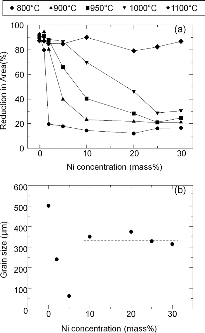
(a) Reduction in area as a function of Ni concentration in Fe–Ni–S alloys. (b) Grain size of Fe–Ni–S alloys annealed at 1350°C and then quenched.
Ductility loss by Ni addition is not related to the change of grain size since optical microscope observation showed that the grain size of austenite (face-centered cubic iron) is over 300 μm due to the high temperature (1350°C) annealing before tensile tests (Fig. 1(b)). Although grain size is dependent on Ni concentration within 5% and drops down to around 50 μm at 5% Ni addition, grain size in this region does not represent the grain size at 1350°C since phase transformation from austenite to ferrite (body-centered cubic iron) occurs during cooling. When Ni concentration exceeds 5%, final microstructure at room temperature is composed of martensite and/or austenite. Thus, we can determine the austenite grain size at 1350°C. From Fig. 1, it is suggested that the Ni concentration dependence on the ductility loss is not connected to the grain size change, but related to grain boundary composition since the fracture is propagated along grain boundaries.
Figure 2 shows the reduction in area for Fe–Mn–Ni–S alloys and the hot ductility is recovered by Mn addition. As Mn can trap S in solid solution as MnS precipitates, it is expected the amount of S segregation at grain boundaries is lowered by Mn addition and then it can lead to improvement of reduction in area even in the Ni containing alloys. Therefore, Ni addition to Fe itself does not decrease the ductility when S concentration in solid solution is quite low. For example, S concentration in solid solution is expected to be lowered down to 0.075 ppm in Fe–0.5Mn–20 ppm S alloys at 800°C.6) On the other hand, as stated before, 20 ppm S addition to Fe does not decrease hot ductility drastically in Ni-free Fe–S binary alloy under our experimental condition. From these results, it can be said that although hot ductility is not affected drastically by S addition in Fe or Ni addition in S killed Fe–Mn alloys, co-addition of Ni and S significantly decreases the hot ductility of Fe when S is not trapped by the sulfide forming element.
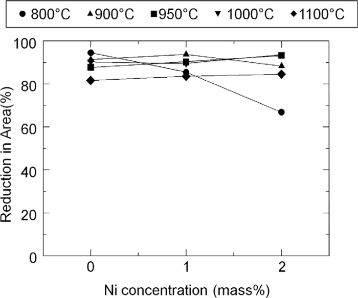
Reduction in area as a function of Ni concentration in Fe–Mn–Ni–S alloys.
Figure 3 shows typical secondary electron image and Auger electron spectra from grain boundary fracture surfaces in Fe–10%Ni–20 ppm S alloy. Fracture surface indicate that the fracture path is almost grain boundaries and Auger electron peaks associated with S segregation are clearly visible on the spectra. These features are the same irrespective of Ni concentration. C segregation that can reduce the amount of S segregation due to the site competition effect7) is not observed on AES spectra from grain boundary fracture surfaces.
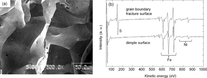
(a) Secondary electron image and (b) AES spectra from fracture surfaces in Fe–10%Ni–20 ppm S alloy.
Figure 4(a) shows AES results on Ni concentration dependence of S segregation at 800°C. The error bar shows the standard deviation that represents the deviation of grain boundary segregation of S depending on grain boundary character. It is noted that at 800°C, Fe matrix is ferrite in the Ni concentration range 0–2% and is austenite when Ni content is more than 5%. However, specimen with Ni concentration of 5% is ferrite at room temperature due to the phase transformation during cooling, as stated before. As shown in Fig. 4(a), the amount of S segregation in austenite is about 5 times larger than that in ferrite. It is well known that during high temperature process such as casting and hot rolling, steels are sometimes fractured along grain boundaries due to S segregation. If steels are composed of austenite phase at high temperatures, the amount of S segregation is expected to increase as compared with that in ferrite phase. Since Ni addition stabilizes austenite phase, this may be one of the reason why Ni enhances grain boundary embrittlement due to S segregation at high temperature. However, it is found that the amount of S segregation is not affected by Ni addition in each ferrite and austenite. Therefore, it cannot be concluded that the mechanism of grain boundary embrittlement enhancement by Ni addition in austenite is the enhancement of S segregation by Ni, in other words, co-segregation of Ni and S.
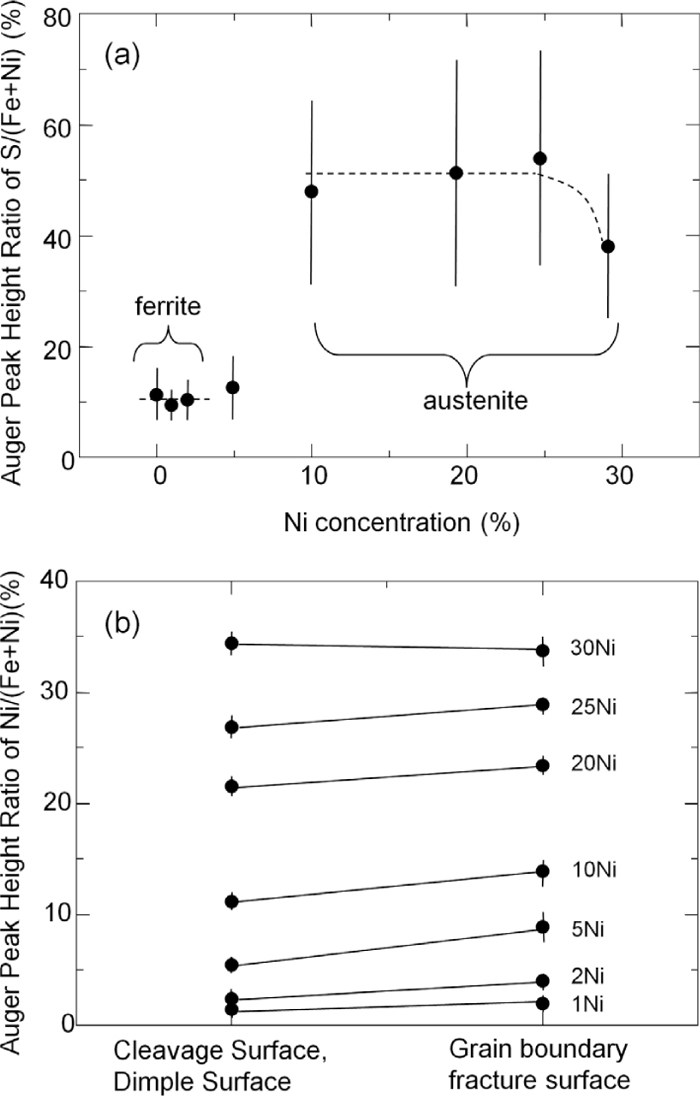
(a) The amount of S segregation at grain boundaries as a function of Ni concentration. (b) The amount of Ni on grain interior fracture surfaces and grain boundary ones.
Figure 4(b) shows the auger peak height ratio of Ni to (Ni+Fe) from grain interior fracture surface (cleavage or dimple surface) and the grain boundaries. As can be seen, Ni enrichment at grain boundaries is quite small. The Ni concentration enrichment ratio at grain boundaries is 1.4–1.7 in ferrite and 1.0–1.2 in austenite at 800°C.
It is known that the solubility of solute atoms and grain boundary enrichment ratio are in inverse proportion relationship.8) In fact, it is reported that Ni enhances grain boundary segregation of Sb in Fe since the solubility of Sb in Fe is lowered by the presence of Ni.9) According to the phase diagram of Fe–S binary10) and Fe–Ni–S ternary11) alloys at 800°C, solubility of S in ferrite is larger than that in austenite, therefore, the result in Fig. 4(a) is quite reasonable. In addition, since solubility of S in ferrite and austenite is not decreased with respect to Ni concentration,11) it is also reasonable that co-segregation of Ni and S is not observed at 800°C. From our experimental results and these phase diagrams, the enhancement of grain boundary embrittlement by Ni addition in Fe–S alloy is not due to the co-segregation of Ni and S at grain boundaries and another mechanism is necessary. As stated before, the kinetics of S segregation, in other words, the diffusion coefficient of S can be affected by external stress and initial dislocation densities.4) The effect of Ni on grain boundary segregation kinetics of S is still unclear, however, since Ni does not change the solubility of S in both ferrite and austenite drastically, it is expected that the atomic interaction between Ni and S in Fe is small.
On the other hand, AES analysis of grain boundary segregation of S in Mn added alloy was impossible since grain boundary fracture surface did not appear. This suggests the amount of S segregation is reduced by MnS precipitation as expected from tensile test. From these results, S segregation is necessary for grain boundary embrittlement in Fe–Ni alloys, but it is still unclear the reason for grain boundary embrittlement due to S segregation since the amount of S segregation is not affected by Ni addition in both ferrite and austenite.
In order to reveal the mechanism of the embrittlement at electronic level, we had performed first-principles pseudopotential calculation and the detail is described in Ref. 5). The first-principles study showed that the S atoms at grain boundary tend to be electronegative due to the charge transfer from Fe to S and the electronegativity of S increase by Ni addition.
Previous theoretical studies show strong embrittling elements forms bonds with the host metal atoms around it,12) which indicates charge transfer occurred from the metal atoms to segregated one. Yamaguchi13) shows that repulsive interaction among the electronegative S atoms at grain boundary in pure Ni is the origin of the grain boundary embrittlement by first-principles calculation. This repulsive interaction between S atoms at grain boundaries can make the grain boundary cohesion weaker. Our results support these considerations and the reason why Ni enhances grain boundary embrittlement in Fe–S alloys is that the degree of charge transfer from Ni to S is larger than that from Fe to S. This is probably because the number of valence electrons in Ni is 2 electrons more than that in Fe and these valence electrons in metal atoms can transfer to S atoms.
In summary, the results presented in this work demonstrate that the hot ductility is not affected by S addition in Fe or Ni addition in S killed Fe–Mn alloy drastically, however, co-addition of Ni and S is detrimental for hot ductility. The mechanism of grain boundary embrittlement enhancement by Ni addition is not related to the co-segregation of Ni and S and it was found the chemical environment change of segregated S by Ni addition plays an important role for the grain boundary cohesion in Fe. In this sense, it is expected that the grain boundary embrittlement due to segregation of other impurites such as Sb, P, H, Te etc. is also enhanced by addition of metal atoms that can offer more valence electrons to these embrittling elements than host metal can.