Abstract
Recently, an increase in the amount of fine ore, such as Marra Mamba or Brazilian concentrated ultra fine, in raw material of sinter ore lowers the permeability of sintering bed and the yield of the sinter ore. The collapse of voids in the sintering bed will cause these problems although the bed has a porous structure. Therefore, controlling the bed structure by including loosely packed regions and densely packed regions in the same packed bed has been discussed. This new idea is named MEBIOS (Mosaic Embedding Iron Ore Sintering). In this report, permeability improvement techniques based on MEBIOS concept were studied. In order to granulate large dense green balls with ordinary sinter feed ore, mathematical simulation and granulation tests by using pan pelletizers were carried out. The influence of rim height and pan diameter on movement of raw material in pan was investigated. Also, influence of rim height and slope angle on hold-up and influence of residence time on diameter of green balls were studied. Finally, this technique was installed in Wakayama No. 5 sinter plant. As a result, yearly average productivity of 1.41 t/m2/h and the use of 135 kg/t-sinter Brazilian concentrated ultra fine ore were achieved with 1350 MJ/t-sinter heat consumption for sintering in 2011.
1. Introduction
Recently, an increase in the amount of fine ore, such as marra mamba or Brazilian concentrated ultra fine, in raw material of sinter ore lowers the permeability of sintering bed and the yield of the sinter ore. The collapse of voids in the sintering bed will cause these problems although the bed has a porous structure. Pre-granulation technique has been developed and applied for such fine ore.1) Recently, controlling the bed structure by including loosely packed parts and densely packed parts in the same packed bed has been discussed.2,3,4,5,6,7) This new idea is named MEBIOS (Mosaic Embedding Iron Ore Sintering).3) In order to embody this idea, granulation of large dense particles using usual sinter feed ore or concentrate is needed. Therefore, mathematical simulation and granulation examinations of Marra Mamba using pan pelletizer were carried out. The influences of size of pan pelletizer and residence time on granulation were studied. After that, this technique was applied practically to Wakayama No. 5 sinter plant.
2. Concept of MEBIOS
The schematic view of the sintering bed structure of MEBIOS method is shown in Fig. 1. The purpose of MEBIOS method is making high density but high permeability packed bed by setting denser parts and looser ones in the same packed bed. For example, high-density large green balls, with a diameter of 5 to 15 mm, are placed in the packed bed to make lower density parts around the balls by a “wall effect” so that the permeability of the packed bed increases.

In order to granulate green balls shown in Fig. 1, selection of granulation device is important. The influence of diameter of drum mixer on granulation has been studied, but it is still unclear. Suzuki8) reported that larger drum mixer and pan pelletizer showed an advantage for granulation because the rolling length of the particle became longer. However, Oyama9) and Yakashiro10) reported that larger drum mixer showed a disadvantage because the granulated particles are easy to collapse in the larger drum mixer. Therefore, mathematical simulation was carried out first for selection of granulation device, and then granulation examinations were carried out for estimating the granulation conditions.
3. Simulation and Experiments
3.1. Mathematical Simulation11)
The simulation conditions are shown in Table 1. Discrete Element Method (DEM) was used for understanding the movement of particles. In order to analyze the granulation condition in the reasonable time, the following suppositions were applied: 1) particles are larger than ordinary quasi-particles to decrease their number, 2) particles have spherical shape, 3) size of the particles are the same, 4) material properties of the particles such as friction coefficient are constant during calculation, 5) influence of moisture is unconsidered. In this simulation, the modified Froude number Fr′ defined as Eq. (1) was set at constant,
|
F
r
′
=
D
(
n
60
)
2
g⋅sinθ
| (1) |
where
D: diameter of pan (m),
n: rotation speed of pan (rpm),
g: gravity (9.8 kg/s2),
θ: slope angle (radian). Also, speed of the particle is divided two parts, the rotation speed on its own axis and the movement speed with granulation device. These speeds of all particles were averaged when the calculation became steady state condition.
Table 1. Simulation conditions.
| Mixer type | Pan | Drum |
|---|
| Dia. (mm) | 500, 1000, 1500, 2000, 2500 3000, 3500 | 500, 1000, 1500, 2000, 2500, |
| Rim height/Length (mm) | 200 | 200 |
| Hold-up ratio (%) | 10 | 10 |
| Dia. of particles (mm) | 10 | 10 |
| Density of particles (g/cm3) | 3.78 | 3.78 |
| Friction coefficient (–) | 0.7 | 0.7* |
| Fr’ number (×10–3) (–) | 8.1 | 8.1 |
* The frictional coefficients of both side walls were assumed to be 0 because the drum length is quite short.
The experimental conditions are shown in Table 2. As will become apparent below, the rotation speed on its own axis of the particle in the pan pelletizer is faster than that in drum mixer. Therefore, pan pelletizer is selected for granulation of green balls shown in Fig. 1. Two pan pelletizers, which diameters were 580 mm and 800 mm, were used for experiments. They are described as 580ϕ and 800ϕ in this report. The pan of 580ϕ is made of stainless steel, and that of 800ϕ is made of ordinary steel. Also, Australian sinter feed ore W, which particle distribution is shown in Table 3, was used for experiments. The modified Froude number Fr′ defined as Eq. (1) was set at constant in most experiments though the diameter of the pan pelletizer was changed.
Table 2. Experimental conditions.
Table 3. Size distribution of sinter feed ore W.
| Size (mm) | –0.25 | 0.25–0.5 | 0.5–1.0 | 1.0–2.0 | 2.0–4.0 | 4.0–7.9 | 7.9–16.0 |
| Ratio (mass%) | 29.01 | 9.46 | 9.51 | 11.53 | 16.97 | 20.88 | 2.64 |
The influence of rim height on hold up, residence time, and diameter of green ball discharged from the pan pelletizer was investigated in Case 1–6, and the influence of slope angle on them was investigated in Case 7 and Case 8. Also, the influence of diameter of pan was investigated in Case 9–11 by comparison with results of Case 6–8. In addition, when the slope angle was changed, Fr′ was also changed in order to investigate the influence of rotation speed on hold up, residence time, and diameter of green ball (Case 6–8 and Case 9–11).
The feed rate is decided by Eq. (2) in order to fix the residence time of model pan pelletizer with actual pan pelletizer:
|
Q
model
=
Q
actual
·
(
D
model
/
D
actual
)
3
| (2) |
where
Dmodel: diameter of pan used for experiment (m),
Qmodel: feed rate for experiment (kg/min),
Dactual: diameter of pan installed in Wakayama (7.5 m),
Qmodel: feed rate at Wakayama (2500 kg/min). The moisture content at granulation,
Fr′, and the time when start to collect sample during granulation were determined by pre-examination. The moisture content was set at 12 mass%, because green balls became larger but the surface of them weren’t wet and they were not collapse after discharge.
Fr′ was set at 1.82 × 10
–3 because the green balls at the stable period, which is mentioned below, became largest when the rotation speed was changed. The green balls discharged from the pan pelletizer were large at the beginning of granulation and then they became smaller. After that, their size became almost constant when the granulation continued longer than residence time. Therefore, the green balls were collected when the granulation continued longer than the residence time. In addition, material flow of pan pelletizer is considered as piston flow, hence hold up divided by feed rate is residence time. Therefore, at least two the granulation examinations were carried out for each case, one was for determining the residence time, the other was for correcting green balls.
3.3. Analysis for Granulation Experiments
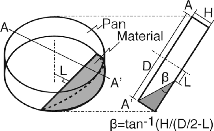
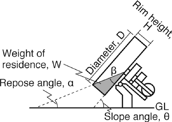
The analytical procedure is as follows. First, a picture of the hold-up state in the pan pelletizer was taken when the granulation examination ended. Next, the weight of hold-up was measured. Then, the shortest distance from the center of the pan to the hold-up L was measured so that the angle β was calculated geometrically (Fig. 3). The volume of the hold-up was calculated by Eqs. (3) and (4),12)
|
H.U
.
calc.
=
D
3
8
tanβ(
2+
B
2
3
1-
B
2
-B
cos
-1
B
)
| (3) |
where
D: diameter of the pan (m),
H: rim height (m),
β: angle of hold-up illustrated in
Fig. 3. In
Eq. (3), a subscript “
calc.” means that value is calculated. Also, the volume of the hold-up calculated as an actual value by
Eq. (5),
|
H.U
.
obs.
=
W
obs.
ρ
| (5) |
where,
Wobs.: weight of hold-up,
ρ: bulk density of green ball. In
Eq. (5), a subscript “
obs.” means that value is measured. The bulk density of green ball of ore W was determined as 1.69 dry-kg/m
3 by measuring the volume of green balls which weight was known in a graduated cylinder. The residence time
R.T. was calculated by
Eq. (6),
|
R.T
.
obs.
=
W
obs.
Q
| (6) |
where,
R.T.obs.: residence time (min),
Q: feed rate (kg/min),
Wobs.: weight of hold-up.
Residence time R.T.calc. was determined by Eq. (6)′ using H.U.calc. in Eq. (3).
|
R.T
.
calc.
=
H.U
.
calc.
⋅ρ
Q
| (6)′ |
In addition, the repose angle of the hold-up α was determined by Eq. (8),
where,
θ: slope of pan (radian).
4. Results
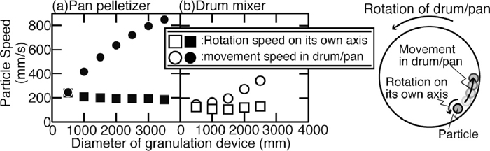
4.1. Influence of Diameter of Pan Pelletizer and Drum Mixer on Particle Speed
The influence of diameters of pan pelletizer and drum mixer on the rotation speed on its own axis of particles and the movement speed of them with pan pelletizer/drum mixer is shown in Fig. 4. The movement speed with pan pelletizer/drum mixer becomes faster when the diameter of pan pelletizer/drum mixer becomes larger. On the other hand, the rotation speed on its own axis is almost constant though the diameter of pan pelletizer/drum mixer becomes larger. The movement speed with pan pelletizer and the rotation speed on its own axis in pan pelletizer are faster than those of drum mixer when their diameters were the same. Therefore, pan pelletizer was selected for granulation examination below because the rotation speed on its own axis in pan pelletizer is faster, which is more important for granulation.
4.2. Influence of Rim Height, Slope Angle, and Diameter of Pan on Residence Condition
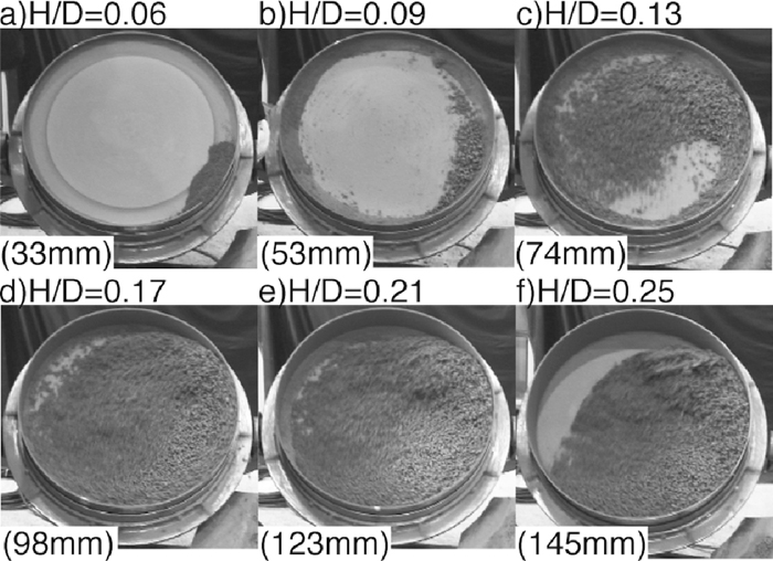
The influence of rim height on the residence condition of 580ϕ which slope angle was 49° is shown in Fig. 5. When H/D was 0.06, the moisture content of raw material decreased from 12 mass% to 11 mass% in order to prevent adherence of raw material on the pan. The adherence of raw material could be prevented when the moisture content was 11 mass%, but the raw material was not well granulated. When H/D was 0.09–0.25, the moisture content of raw material was 12 mass% at the granulation. When H/D was 0.09, raw materials adhered to the rim of the pan at the start of granulation, and about 8 minutes later, charged raw material could not stay in the pan because it slips on the adherent raw material. When H/D was 0.13, charged raw material adhered where most of the raw material stayed in the pan, right bottom part in these examinations. The adhered materials moved to top part of the pan, and then drop to the bottom and adhered again periodically. When H/D was 0.17–0.25, most part of inside of the pan was covered with raw materials during granulation. In addition, there was a gap in the upper left part of the pan when H/D was 0.25.
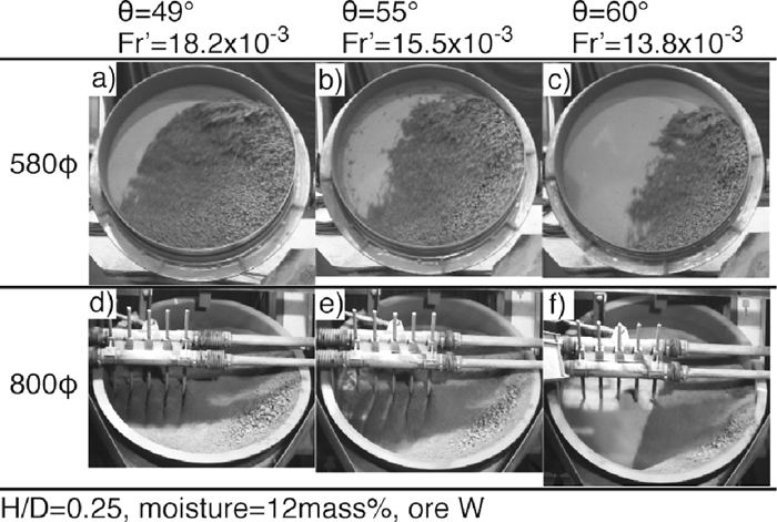
The influence of slope angle on hold-up condition was investigated using 580ϕ which H/D was 0.25. Variation of hold-up conditions when the slope angle was changed is shown in Fig. 6. The raw materials moved smoothly even if the slope angle increased. The upper left gap inside the pan became larger when the slope angle increased. The variations of the hold-up condition of 800ϕ, which H/D was 0.25, when the slope angle was changed is also shown in Fig. 6. The hold-up conditions of 800ϕ were similar to those of 580ϕ according to the visual observation.
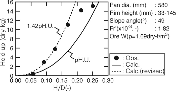
4.3. Influence of Rim Height and Slope Angle on Weight of Hold-up in 580ϕ
The influence of rim height the hold-up weight was investigated by using 580ϕ. The relationship between H/D and hold-up weight was shown in Fig. 7. When H/D increased, the hold-up weight increased. However, the increase of weight became gently when H/D was larger than 0.17. It is because the gap of upper left of the pan became larger when H/D was larger than 0.17 as mentioned in Fig. 5. In Fig. 7, calculated hold-up weight, which is calculated with the estimated volume of hold-up by Eq. (3) and the bulk density of ore W green ball, is described as solid line. The calculated hold-up weight does not agree with measured hold-up weight. Therefore, the calculated hold-up weight was revised in order to agree with measured hold-up weights, which H/D was 0.17 or less because there was no gap with those conditions. The revised calculated hold-up weight is described as broken line in Fig. 7. This is in good agreement with the measured hold-up weight when H/D was 0.17 or less.
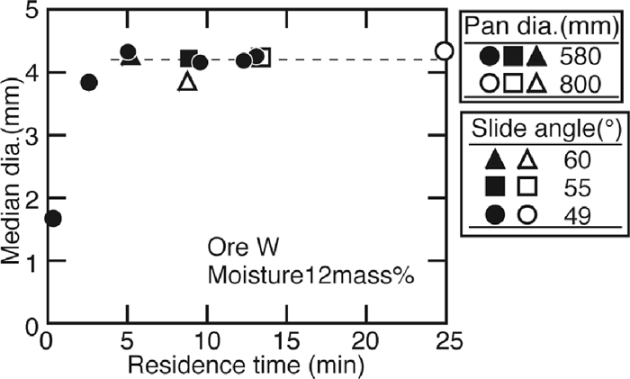
The relationship between the median diameter of green ball and residence time, which is calculated with measured hold-up weight and feed rate, is shown in Fig. 8 described as solid marks. The results of 800ϕ are plotted as open marks. When the residence time became 5 min or more, the results of 580ϕ with the same Fr′ number but different rim height, described as solid circles, converged to 4.2 mm. The results of 580ϕ with the same rim height but different slope angle, described as a solid square and a solid triangle, were about 4.2 mm and their residence times were longer than 5 min. Moreover, the residence times of 800ϕ was longer than 5 min and the median diameters of green balls were about 4.2 mm even though the residence time is changed by controlling the slope angle. In addition, the residence times of 800ϕ were longer than those of 580ϕ under the same angles. It is because the roughness of these pans affected the hold-up conditions. The surface of the pan of 580ϕ was smoother than that of 800ϕ because the pan of 800ϕ was slightly rusted. Therefore, materials could be held easier in 800ϕ.
5. Discussion
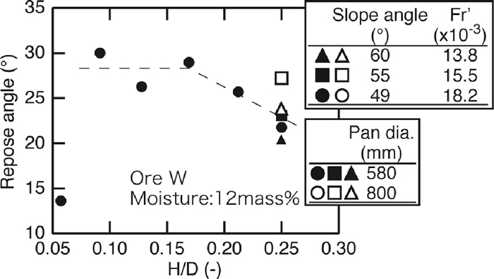
As shown in Fig. 7, estimated hold-up weight, calculated with volume of hold-up from Eq. (3) and bulk density of the green ball, is in good agreement with measured hold-up weight when a correction coefficient was applied. The difference between the packed situation of the green balls in the graduated cylinder and that in the pan would result in the necessity of the correction coefficient. In other words, there is a mixture of full granulated green balls, smaller ones which are being granulated, and un-granulated fines in the pan, so that the mixture packed more tightly than in the graduated cylinder. The calculated hold-up weights do not agree with measured ones when H/D is larger than 0.17 because there is the gap in the pan. In order to clarify the reason why the gap formed, the repose angle was calculated from Eq. (8). The relationship between H/D and repose angle is shown in Fig. 9. The repose angle decreased about 2° when H/D was larger than 0.17. According to the visual observation of the inside of the pan after granulation, the size of the material in the pan was almost the same as the discharged green balls and few un-granulated fines were found. This means that the most of raw materials became green balls so that the repose angle decreased because the residence time was longer than enough to granulate green balls for charged fines when H/D was larger than 0.17 and the feed rate was 1.16 kg/min. The time for which the charged fines became green balls was 5 min because the diameter of green balls converged to about 4.2 mm after 5 min in this examination.
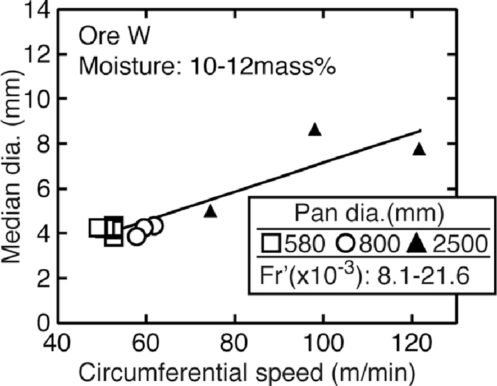
The sizes of the green balls were almost the same between 580ϕ and 800ϕ. The influence of rotation speed on its own axis is more important than the movement speed with pan for granulation because granulation makes progress with adhesion of adherence around nucleus like a snow ball. However, the rotation speed on its own axis was not affected by the diameter of the pan mentioned in Fig. 4. Therefore, the sizes of the green balls were almost the same. In order to confirm this idea, the same granulation examination was carried out using a pan pelletizer described as 2500ϕ, which diameter was 2500 mm, rim height was 400 mm, and H/D was 0.16. In this examination, the rotation speeds were changed as 9.5 rpm, 12.5 rpm, and 15.5 rpm. The residence time estimated from broken line in Fig. 7 was 9.5 min. The relationship between the median diameters of green balls with the circumferential speeds of the pan pelletizers is shown in Fig. 10. The green balls granulated by 2500ϕ were larger than those granulated by 580ϕ or 800ϕ, and there was a correlation between the circumferential speed and green ball size. According to the simulation result shown in Fig. 4, the movement speed with pan becomes larger when the diameter of the pan becomes larger. As mentioned above, quasi-particles are easy to collapse in the larger drum mixer.9,10) Okada13) also reported that dispersion and re-cohesion of micro particles is important for granulation. He found that a similar phenomenon, which collapse of green balls and re-granulation would occur in 2500ϕ, in spite of anionic polymer dispersant (APD). On the other hand, few un-granulated fines were found in 580ϕ and 800ϕ. It would mean that collapse of green balls was difficult to occur in a smaller pan so that the size of the green balls became almost the same. Therefore, when the diameter of the pan becomes larger, collapse of green balls and re-granulation occur actively so that the size of them increases.
6. Practical Application of MEBIOS Concept in Wakayama
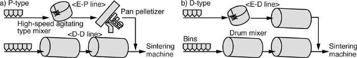
According to those results mentioned above, P-type separate granulation system was developed to embody the concept of MEBIOS. The comparison of P-type separate granulation system with the conventional separate granulation system 14,15) is illustrated in Fig. 11. In the separate granulation system, raw materials are divided into two groups. The raw materials, which are more difficult to granulate than others due to finer size, etc., are mixed with water by a high-speed agitating type mixer and then granulated by a drum mixer in the conventional separate granulation system. On the other hand, pan pelletizer(s) is used in P-type granulation system instead of drum mixer. Other raw materials are granulated by drum mixers. After that they are mixed and charged to sintering machine.
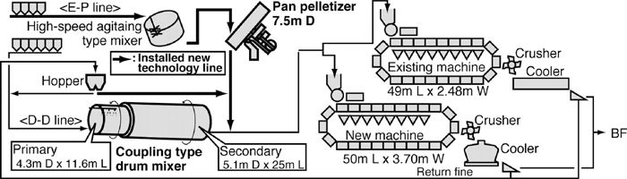
In order to increase the sinter productivity, a new strand and the reinforced granulation process were constructed in Wakayama No.5 sintering plant. P-type separate granulation system was also installed at the same time. Furthermore RF-MEBIOS16,17,18,19,20,21,22) method was installed. The construction was finished in January 2009, and the plant has started the commercial operation. The schematic view of Wakayama No. 5 sinter plant is described in Fig. 12.
The comparison of the averages of the sinter productivity, the amount of Brazilian concentrated ultra fine (PF) in raw material, and the quantity of heat for bonding in Wakayama No. 5 sinter plant with those of in Japan in 2011 is indicated in Fig. 13. Higher productivity (1.41 t/m2/h), larger amount of PF usage (135 kg/t-sinter), and lower energy consumption (1350 MJ/t-sinter) were achieved in Wakayama No. 5 sinter plant. The increase of permeability of the sintering bed by P-type separate granulation system and RF-MEBIOS make the combustion efficiency of bonding agent higher.
7. Conclusion
In order to embody the concept of MEBIOS for the permeability improvement, mathematical simulation for the movement of particles in granulation devices and granulation examinations of Marra Mamba using a pan pelletizer were carried out. The following are the summary of this work:
(1) When the diameter of pan pelletizer/drum mixer becomes larger, the rotation speed on its own axis of the particles does not change significantly, but the movement speed of the particles becomes larger according to the mathematical simulation using DEM. Also, these speeds of pan pelletize are higher than that of drum mixer. Therefore, pan pelletizer is suitable for granulation of large green ball.
(2) In this examination, the diameters of the green balls granulated by the pan pelletizers, which diameters of the pans were 580 mm and 800 mm, were almost the same. On the other hand, the diameter of the green balls granulated by the pan pelletizer with 2500 mm diameter pan was larger than them. It is believed that collapse of green balls and re-granulation occurs actively in a larger pan pelletizer so that the size of the green balls increased.
(3) P-Type granulation system based on MEBIOS has been developed and these techniques have been installed in Wakayama No. 5 sinter plant. The operational results have shown increase in productivity of sinter.
References
- 1) For example, S. Funada and T. Saito: Tetsu-to-Hagané, 43 (1957), 880.
- 2) T. Kawaguchi and T. Usui: ISIJ Int., 45 (2005), 414.
- 3) E. Kasai, S. Komarov, K. Nushiro and M. Nakano: ISIJ Int., 45 (2005), 538.
- 4) T. Kawaguchi: CAMP-ISIJ, 5 (1992), 129.
- 5) C. Kamijo, M. Matsumura and T. Kawaguchi: CAMP-ISIJ, 17 (2004), 120.
- 6) C. Kamijo, M. Matsumura and T. Kawaguchi: ISIJ Int., 45 (2005), 544.
- 7) T. Kawaguchi, C. Kamijo and M. Matsumura: Tetsu-to-Hagané, 92 (2006), 779.
- 8) S. Suzuki, K. Sato and M. Fujimoto: Tetsu-to-Hagané, 73 (1987), 1932.
- 9) N. Oyama, H. Sato, K. Takeda, T. Ariyama, S. Matsumoto, T. Jinno and N. Fujii: ISIJ Int., 45 (2005), 817.
- 10) K. Yakashiro and T. Imai: CAMP-ISIJ, 18 (2005), 175.
- 11) J. Kano, E. Kasai, F. Saito and T. Kawaguchi: ISIJ Int., 45 (2005), 500.
- 12) Zohryubinran, APPIE, Ohmsha, Tokyo, (1975), 116.
- 13) T. Okada, J. Okazaki, M. Nakano, K. Kono and S. Miura: Tetsu-to-Hagané, 92 (2006), 735.
- 14) T. Kawaguchi, K. Kurita, S. Sato and K. Takata: Tetsu-to-Hagané, 73 (1987), 1924.
- 15) T. Kawaguchi, K. Kurita, S. Sato and K. Takata: Tetsu-to-Hagané, 76 (1990), 1642.
- 16) K. Watanabe, M. Yoshikawa, C. Kamijo, M. Hara. T. Kawaguchi and M. Matsumura: CAMP-ISIJ, 23 (2010), 6.
- 17) Y. Yamaguchi, C. Kamijo, T. Kawaguchi and M. Matsumura: CAMP-ISIJ, 22 (2009), 832.
- 18) M. Matsumura, C. Kamijo, Y. Yamaguchi and T. Kawaguchi: CAMP-ISIJ, 22 (2009), 833.
- 19) Y. Nakagawa, K. One, H. Aoki, K. Imagawa, T. Okubo and C. Kamijo: CAMP-ISIJ, 22 (2009), 834.
- 20) Y. Yamaguchi, C. Kamijo and T. Kawaguchi: CAMP-ISIJ, 24 (2011), 195.
- 21) Y. Nakagawa, K. One, H. Aoki, K. Imagawa, T. Okubo and Y. Yamaguchi: CAMP-ISIJ, 24 (2011), 196.
- 22) M. Matsumua, Y. Yamaguchi, M. Hara, C. Kamijo, T. Kawaguchi and Y. Nakagawa: ISIJ Int., 53 (2013), 34.
;%0A%09%09%09newWindow.document.open();%0A%09%09%09newWindow.document.write('<img src=%22./Graphics/53_1497_tbl_1.jpg%22>');%0A%09%09%09newWindow.document.close();%0A%09%09)