Abstract
Applications of ultra-high strength steel sheets to automotive bodies have expanded steadily in recent years. Various methods are used to evaluate resistance to hydrogen embrittlement (HE), which is one problem of ultra-high strength steels. In this study, the critical HE conditions obtained by the SSRT, CSRT and 4-point bending test were compared by using the same materials. The materials were two ultra-high strength steel sheets with tempered martensite microstructures, one with the SCM435 composition and the other a V-added steel containing many hydrogen trapping precipitations. The specimens were charged with hydrogen by the cathodic charging method. The specimens used in the SSRT and CSRT were machined with notches on both sides of the parallel part. The values of the stress concentration factor (Kt) of the specimens were 4.26 and 1.76. A coupon-shaped specimen was used in the 4-point bending test. The critical HE conditions evaluated by the average applied stress and the average hydrogen content of the specimen were different depending on the test methods. The HE conditions were also evaluated by the local stress and the local accumulated diffusible hydrogen content at the fracture initiation point. The critical condition evaluated by the 4-point bending test was located in a higher stress and higher hydrogen content region compared with the critical conditions obtained by the CSRT and the SSRT.
1. Introduction
In steels with tensile strength of 1000 MPa and higher, delayed fracture, which means fracture of ultra-high strength steels caused by hydrogen, may occur even under atmospheric corrosion conditions. The F13T grade high strength bolt is well-known for a delayed fracture accident.1) Based on this background, round bar or square bar specimens have mainly been used in this research field. Recently, however, the demand for delayed fracture evaluation of automotive steel sheets has increased in response to increasing application of ultra-high strength steel sheets with tensile strength of 1000 MPa and higher to high strength automobile bodies. In order to evaluate the risk of delayed fracture, it is generally considered that resistance to hydrogen embrittlement (hereinafter, HE), which means the HE susceptibility of steels and the hydrogen entry property, should be evaluated.2) The focus of this study is HE susceptibility. There are many test methods for HE evaluation, for example, the Constant Load Test (CLT),2,3) Slow Strain Rate Test (SSRT),4,5,6,7,8,9,10) Conventional Strain Rate Test (CSRT)11,12,13,14) and 4-point bending test.15,16) Delayed fracture of ultra-high strength steel sheets for automobiles is evaluated with not only virgin material but also with plastic deformed materials simulating press forming because automotive steel sheets are generally used after press forming.17) An example of an investigation method for the critical HE condition of strained sheet steels is the U-bending method, in which a specimen is bent to a U-shape and tightened with a bolt.18,19,20,21) Various studies have investigated the validity of those evaluation methods, and various HE evaluations of steels have been conducted with those methods. However, the differences between the critical conditions for HE obtained by those methods are not clear. Therefore, the object of this study is to clarify the difference between the critical HE conditions of steels obtained by the SSRT, CSRT and 4-point bending test under a constant load condition. A 1300 MPa-class JIS-SCM435 steel and a 1400 MPa-class V-added steel were selected as the representative materials to evaluate.
2. Experimental Method
2.1. Materials and Specimen Dimensions
A JIS-SCM435 steel, which is often used in HE studies, and a V-added steel, which has been developed recently and has good HE resistance,2,3,22) were used. The chemical compositions of the steels are shown in Table 1.
Table 1. Chemical compositions of steels used.
| (mass%) |
| Steels | C | Si | Mn | P | S | Al | Cr | Mo | V | N |
| SCM435 | 0.35 | 0.24 | 0.79 | 0.023 | 0.016 | 0.036 | 1.09 | 0.15 | – | 0.005 |
| V-added steel | 0.41 | 0.20 | 0.71 | 0.005 | 0.005 | 0.037 | 1.20 | 0.64 | 0.30 | 0.004 |
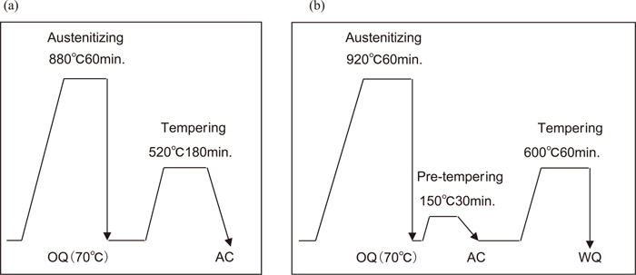
In preparing the JIS-SCM435 steel, an ingot with the chemical composition shown in Table 1 was heated to 1200°C, and its thickness was reduced to 5 mm by forging and rolling, which were followed by pickling. The sheet was then cold rolled to the thickness of 2.6 mm, followed by the heat treatment shown in Fig. 1(a). Table 2 shows the mechanical properties of the JIS-SCM435 steel obtained by a tensile test of a JIS 13A specimen with the parallel part width of 20 mm and gage length of 80 mm.
Table 2. Mechanical properties of steels used.
| Steels | YS/MPa | TS/MPa | El. (%) | Type of specimen |
|---|
| SCM435 | 1003 | 1323 | 7 | JIS No. 13 A
(G.L.: 80 mm) |
| V-added steel | 1302 | 1418 | 16 | JIS No. 5
(G.L.: 50 mm) |
The V-added steel was prepared by heating a vacuum melted ingot of the chemical composition in Table 1 to 1200°C, followed by hot rolling to the thickness of 5 mm. The hot-rolled sheet was treated at 920°C for 60 min and air-cooled, followed by the heat treatment shown in Fig. 1(b). A preliminary temper treatment at 150°C for 30 min was conducted immediately after quenching to decrease the risk of hydrogen cracking because several days had elapsed between quenching and tempering. The thickness of the specimen was decreased to 1.0 mm by mechanical grinding. Table 2 shows the mechanical properties obtained by a tensile test of a JIS No. 5 specimen with the parallel part width of 25 mm and gage length of 50 mm.
2.2. Hydrogen Embrittlement Evaluation Method
The test conditions of the SSRT, CSRT and 4-point bending constant load test are described below.
2.2.1. Conditions of SSRT
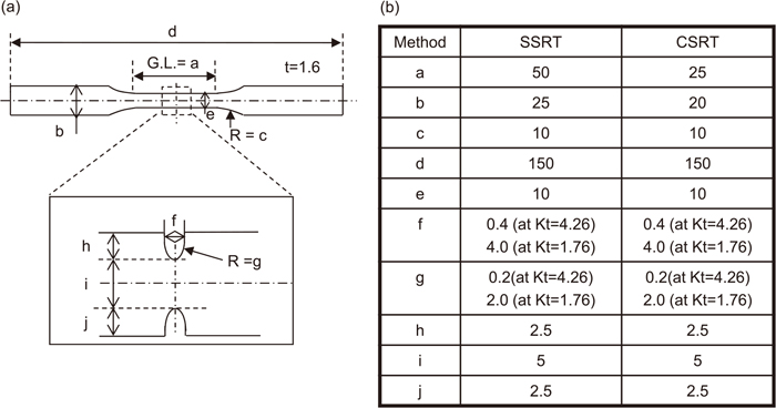
The specimen dimensions are shown in Fig. 2(a). The parallel length is 50 mm and the parallel width is 10 mm. Notches with the depth of 2.5 mm were machined on both sides of the parallel part of the specimen. The curvature radius of the notch root is 0.2 mm and 2 mm, as shown in Fig. 2(b). The calculated values of the stress concentration factor Kt with these two curvature radii are 4.26 and 1.76, respectively. Kt was calculated by Eq. (1).23)
|
K
t
=1+
[
W/b-1
1.55W/b-1.3
b
ρ
]
n
| (1) |
n is defined as shown in Eq. (2).
|
n=
(
W/b-1
)
+0.5
a/ρ
(
W/b-1
)
+
a/ρ
| (2) |
where, 2W is the parallel width, a is the depth of the notch,
ρ is the curvature radius of the notch, and b is defined by
Eq. (3).
The crosshead speed in the SSRT was 0.001 mm/min. Strictly speaking, this test should be called a slow speed tensile test because it is not possible to define the strain rate at the notch root of the specimen at which the crack initiates. Generally, however, this kind of test is called the SSRT and therefore is also called the SSRT in this study.
The SSRT were conducted under three sets of conditions. One was a test in the air environment after cathodic charging of hydrogen for 48 h (hereinafter, test in air after cathodic precharging), the second was a test with continuous cathodic charging after cathodic precharging of hydrogen for 48 h (hereinafter, test with cathodic charging), and the third was a test in air without cathodic charging (hereinafter, test in air). Cathodic hydrogen charging was conducted with the current density of 10 A/m2 in an aqueous solution containing 3wt%NaCl+0.5wt%NH4SCN. The specimen was removed from the test apparatus immediately after the end of the test, and a sample for hydrogen analysis was cut from the specimen at a position 5 mm from the fracture position.
2.2.2. Conditions of CSRT
The dimensions of the specimen are shown in Fig. 2(b). The parallel length is 25 mm, which is different from that of the specimen for the SSRT; however, the parallel width, the position of the notch, the notch depth and the curvature radius of the notch are the same as those of the SSRT specimen. The thickness of the specimen was 1.5 mm. Specimens were finished with mechanical grinding of 0.5 mm from both surfaces to remove scratch defects. The values of the stress concentration factor Kt were 4.26 and 1.76 in the specimens with the notch root radii of 0.2 mm and 2 mm, respectively. The specimens were charged with hydrogen by means of cathodic charging. In the CSRT, it is necessary to charge hydrogen until the hydrogen content became homogenous in the thickness direction. Therefore, the hydrogen charging time required to make hydrogen distribution homogeneous was investigated for the coupon samples with the thickness of 1.6 mm and width of 10 mm. As the result, the required charging time was determined to be 48 h for the JIS-SCM435 steel and 72 h for the V-added steel. The aqueous solutions for cathodic charging used in this study were 3 wt% NaCl solutions with NH4SCN contents of 0.3 g/L or 3 g/L. A 0.1M NaOH aqueous solution was also used in the experiment with the V-added steel. The hydrogen content was controlled by the current density condition, which was varied in the range of 10–50 A/m2 in the case of the 3 wt% NaCl solution and the range of 5–100 A/m2 in the case of the NaOH solution. In hydrogen charging, a 20 mm area around the center of the parallel part, which included the notch, was charged with hydrogen, and the other part was covered with tape and plastic silicon for insulation. The charged specimens were tested by the CSRT method with the crosshead speed of 1 mm/min immediately after the end of hydrogen charging. The test time was approximately 1–5 min. The sample for hydrogen analysis was cut out from the exposed part of the specimen immediately after fracture.
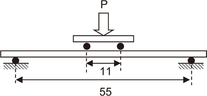
2.2.3. Conditions of 4-point bending test16)
The dimensions of the specimen were 10 mm in width, 65 mm in length and 1.6 mm in thickness. Cathodic hydrogen charging was conducted in an aqueous solution containing 3wt%NaCl+0−20g/L–NH4SCN at 25°C with current densities of 0.1–10 A/m2. The hydrogen content was controlled by the NH4SCN concentration and the current density. The test was conducted as follows: First, the specimen was charged with hydrogen for 48 h without loading; this is called pre-charging. Next, loading was applied to the specimen by 4-point bending, and hydrogen charging was continued under the same condition as in pre-charging. The fracture time was counted from the start of loading. The applied stress at the fracture initiation position was controlled at the outer surface and width center of the 4-point bending specimen. The applied load was calculated by the 3-dimensional finite element method. The critical condition for HE fracture was defined as the highest applied load between the conditions unfractured after 100 h.
2.3. Hydrogen Analysis Method
The diffusible hydrogen content in the specimens was analyzed by thermal desorption analysis with a mass spectrometer in the SSRT and with a gas chromatograph with an Ar carrier gas in the other tests. The heating rate was 100°C/h or 200°C/h, and the temperature range of the analysis was from ambient temperature to 600°C. The analysis method was different from the test method because the tests by the respective methods were conducted by different research institutes. The specimens for hydrogen analysis were cut out at a position 5 mm from the fracture position in the case of the SSRT and 10 mm from the fracture position in the case of the CSRT specimen. In the 4-point bending test, the samples were cut out from specimens without loading, which were charged under the same conditions as the test specimens. The diffusible hydrogen content (hereinafter, HD) was defined as the sum of the desorbed hydrogen at temperatures up to 300°C.
2.4. Calculation Method of Local Stress and Local Diffusible Hydrogen Content at Fracture Initiation Position of Specimens
The local stress and local HD at the fracture initiation position in the SSRT, CSRT and 4-point bending test were calculated by 3-dimensional elastic-plastic finite element analysis.
2.4.1. Calculation of Local Stress and Local Diffusible Hydrogen Content at Fracture Initiation Position in SSRT
The fracture initiation position in the SSRT was the peak stress point in the tensile axis direction. The local stress and local HD at that point were calculated from the result of the elastic-plastic finite element method analysis of a one-eighth model, considering the symmetry of the specimen dimensions. The peak stress in the tensile axis direction and the peak hydrostatic stress around the notch root were calculated for various loading conditions. Because of the extremely slow deformation speed of the SSRT, it is considered that diffusible hydrogen diffuses by stress induced diffusion and the hydrogen content reaches a distribution corresponding to the hydrostatic stress distribution. Therefore, the local HD at the peak stress point in the tensile axis direction was calculated by Eq. (4).24,25,26,27,28)
|
H
*
=H×exp{
-(
σ
h
-
σ
hmin
)×ΔV
RT
}
| (4) |
where, H is the average H
D in the specimen analyzed by thermal desorption analysis,
σh is the hydrostatic stress at the peak stress point in the tensile axial direction,
σhmin is the hydrostatic stress at a position sufficiently far from the notch root, Δ
V is 2×10
−6 m
3/mol,
26) which is the partial molar volume fraction of a hydrogen atom in bcc-Fe,
R is the gas constant, and
T is 300 K as the test temperature.
2.4.2. Calculation of Local Stress and Local Diffusible Hydrogen Content at Fracture Initiation Position in CSRT
The fracture initiation position in the CSRT is the peak stress point in the tensile axial direction, which is the same as in the SSRT. The stress at that point was calculated by the same method as described in 2.4.1. On the other hand, the local HD at the fracture initiation point was equal to the analysis result because stress induced diffusion did not occur during the test due to the fast deformation rate in this type of test.
2.4.3. Calculation of Local Stress and Local Diffusible Hydrogen Content at Fracture Initiation Position in 4-point Bending Test
The fracture initiation position in the 4-point bending test is the outer surface of the specimen, and the stress set in 2.2.3 is the same as the stress at the fracture initiation position. As in the SSRT, the diffusible hydrogen in the specimen is distributed at the fracture initiation position corresponding to the hydrostatic stress distribution because a constant load is applied to the specimen and the testing time is long enough for stress induced diffusion. Therefore, the local HD which accumulated at the fracture initiation position, which was the outer surface of the specimen, was calculated by Eq. (4), where σh and σhmin are the hydrostatic stress at the center of width on the outer surface and the center of width on the inner surface, respectively.
3. Experimental Results
3.1. Results of SSRT
The Kt of the SCM435 steel and V-added steel specimens was 4.26. The stress-displacement curves of the specimens are shown in Figs. 4(a) and 4(b), respectively. With both materials, the shapes of the stress-displacement curves were almost the same under all conditions. However, the amount of displacement to fracture was different depending on the material. The displacement of the SCM435 steel up to fracture in the SSRT in air was the largest and the displacement in the SSRT with cathodic charging was the smallest. The displacement of the V-added steel up to fracture in the SSRT in air was also the largest, and the displacement in air after cathodic precharging and the displacement with cathodic charging were smaller than that in air and were almost the same. To investigate the reason for this difference, HD after cathodic precharging before starting the test and after finishing the test were compared. As the result, in the SCM435 steel, the HD in the specimen after cathodic precharging before the SSRT was 2.05 mass ppm (hereinafter, ppm), and the HD after finishing the test in air after cathodic precharging was 1.11 ppm, which was about one-half of the HD before starting the SSRT. On the other hand, the HD after finishing the test with cathodic charging was 2.27 ppm, which increased about 10% compared with the specimen before starting the SSRT. The reason for this difference is considered to be that, in the SSRT in air after cathodic precharging, the diffusible hydrogen in the specimen was released during the test, whereas in the SSRT with cathodic charging, the diffusible hydrogen was trapped at the dislocations introduced during the test. Because the fracture displacement decreased with increasing diffusible hydrogen content, it is understood that the test condition dependence of the displacement up to fracture is the result of deterioration of ductility caused by hydrogen. On the other hand, in the V-added steel, HD of 10.23 ppm after cathodic precharging before the test start was almost the same as the HD of 10.71 ppm after finishing the SSRT in air after cathodic precharging. The HD after the SSRT with cathodic charging was 11.22 ppm, and HD increased about 10% in comparison with the HD before the test start. This behavior was similar to that of the SCM435 steel.
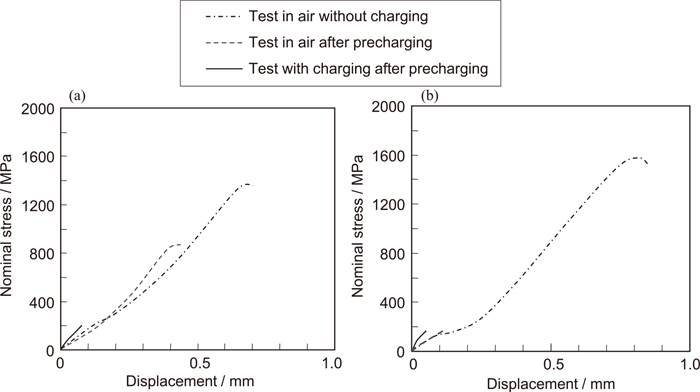
In the V-added steel, it is considered that diffusible hydrogen was not released during the SSRT in air because the diffusion coefficient of diffusible hydrogen in the V-added steel was lower than in the SCM435 steel. Therefore, it is considered that the fracture displacement of the V-added steel in the test in air after cathodic precharging decreased extremely compared with the fracture displacement of the test in air, as is the case of the test with cathodic charging.
3.2. Results of CSRT
The relationships between the engineering fracture stress and the diffusible hydrogen at the cross section of the notch part obtained in the CSRT with the SCM435 steel and the V-added steel are shown in Figs. 5 and 6, respectively. The fracture origin of the SCM435 steel at the Kt of 4.26 was the prior austenite grain boundary, and fracture stress decreased extremely with increasing HD. However, the fracture origin of the specimen with the Kt of 1.76 was quasi-cleavage at the HD of 1 ppm or less and the prior austenite grain boundary at the HD of 1.5 ppm or more. In the V-added steel, the fracture stress was almost constant up to the HD of 4 ppm independently of Kt, as shown in Fig. 6, and the fracture origin was quasi-cleavage. At HD > 4 ppm, the fracture origin changed to the prior austenite grain boundary and fracture stress decreased extremely. The decrement of the fracture stress was larger in the specimen with the Kt of 4.26. This is considered to be because the maximum stress at the notch root in the specimen with the Kt of 4.26 is larger than that in the specimen with the Kt of 1.76. From a comparison of Figs. 5 and 6, the HD at which the fracture stress rapidly decreased in the V-added steel was larger than that in the SCM435 steel. This is considered to be due to the hydrogen trap effect of vanadium carbide.22)

Figure 7 shows the typical relationships between the applied stress and time to fracture of the SCM435 steel16) and the V-added steel.16) The time to fracture was counted from the start of loading. In both steels, under the fracture condition, a tendency was observed in which the specimens fractured in a short time after loading. On the other hand, specimens that did not fracture shortly after loading did not fracture until 100 h after loading, and the stress was judged as an unfractured condition. The reason why the fracture condition was determined in a short time after loading is considered to be due to three factors, as follows. One is that loading was started after the specimens were charged with hydrogen up to the equilibrium HD corresponding to the current density of charging, the second is that the HD was maintained during the 4-point bending test with hydrogen charging, and the third is that the fracture origin was near the outer surface, where hydrogen was supplied almost simultaneously with deformation. In other words, the diffusible hydrogen at the fracture origin on the outer surface was distributed to the equilibrium condition corresponding to the hydrostatic stress within a short time after loading. In the 4-point bending test, it is considered that the HD after the test was larger than that before the test because HD increased corresponding to the plastic deformation introduced by bending. However, the increment of HD is presumed to be small, as the equivalent strain at the outer surface introduced by bending was about 1% even under the maximum stress condition.

Figures 8 and 9 show the relationships between the critical stress condition of HE fracture and HD for the two steels, respectively. In both steels, the critical stress decreased with increasing HD. The critical stress decreased extremely at the HD over 2.5 ppm in the SCM435 steel and over 8.0 ppm in the V-added steel. In a comparison at the same HD, the critical stress of the V-added steel was higher than that of the SCM435 steel.
4. Discussion
Y. Hagihara et al.11,13) presented results in which the critical condition of HE of TS 1300 MPa grade tempered martensitic steel obtained by the SSRT with a circumferential notched specimen were almost the same as by the CSRT in the case evaluated by the local stress and local HD at the fracture initiation position.24) Based on this result, under the conditions in that paper, it is judged that the mechanism of HE was the same in the CSRT and SSRT. In this chapter, the mechanisms of HE in the SSRT, CSRT and 4-point bending test will be considered by comparison and analysis of the critical condition of HE with the local stress and local HD at the fracture initiation position. Although specimens with Kt of 4.26 and 1.76 were used in the SSRT and CSRT in this study, only the results obtained with the Kt of 4.26 were used in the following discussion.
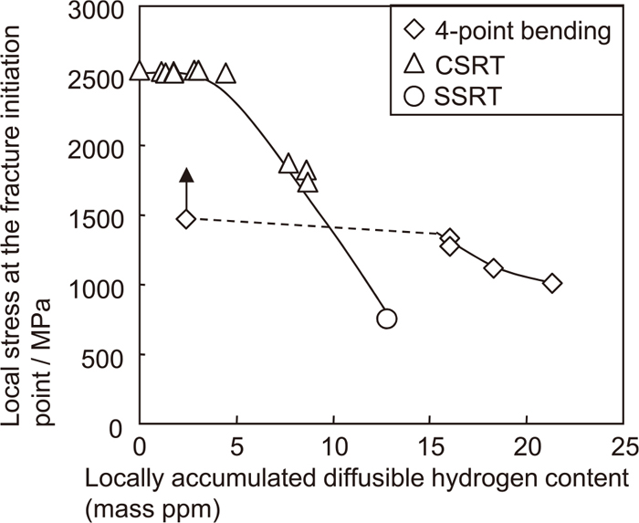
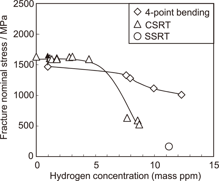
First, the results of the SCM435 steel will be discussed. The critical conditions of HE fracture are shown in Fig. 10, in which the evaluation indexes are the applied stress and the average HD in the specimen. The applied stress was the average stress at the cross section of the notch root in the SSRT and CSRT, and the outer stress of the specimen in the 4-point bending test. In the SSRT, the result obtained in the test with cathodic charging was used. The critical fracture stress was located in order corresponding to the SSRT, CSRT and 4-point bending test from low stress and low hydrogen content. On the other hand, Fig. 11 shows the evaluation results of the critical condition of HE with the local stress and the local HD at the fracture initiation point. The local fracture stress decreased with increasing local HD. In this evaluation, the critical conditions were located in a narrow band independently of the test method in the comparison of the evaluation with the applied stress and the average HD in the specimen; however, the critical condition of the 4-point bending test was located in a higher stress-higher hydrogen content region than those of the SSRT and CSRT. In this study, the local HD ranges in the SSRT and CSRT were different from that in the 4-point bending test. Therefore, the critical fracture condition obtained by those methods must be compared in the same local HD range in a future study.

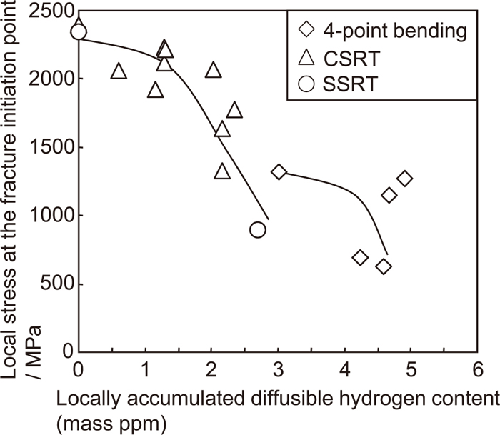
Next, the results of the V-added steel will be discussed. Figure 12 shows the critical conditions of HE fracture, in which the evaluation indexes were the applied stress and the average HD in the specimen. The critical fracture condition in the CSRT was located in a lower stress-lower HD region than those in the 4-point bending test at the HD of 8 ppm and higher. Although the data points of the SSRT is presumably located on the extrapolation of the CSRT data points, SSRT data number is not enough to confirm it in the present study. Additional SSRT data points are necessary, and some additional data points will be obtained in the subsequent study. Figure 13 shows the evaluation results of the critical condition of HE with the local stress and the local HD at the fracture initiation point. The local fracture stress decreased with increasing local HD in the same way as with the SCM435 steel. The critical fracture condition of the 4-point bending test was located in the higher stress-higher diffusible hydrogen content region than those of the CSRT and SSRT.
The critical HE fracture conditions in the SSRT and CSRT as kinds of uniaxial tensile tests with notched specimens were different from the critical condition in the 4-point bending test. The reason is conjectured to be that the plastic constraint in sheet steels is smaller than that in round bar specimens, and as a result, plastic deformation occurs more easily in sheets, and the difference in the amount of plastic deformation influences the critical fracture conditions.
5. Conclusions
The critical hydrogen embrittlement conditions of ultra-high strength steel sheets with microstructures of tempered martensite were evaluated by the SSRT, CSRT and 4-point bending test. The materials were SCM435 steel with tensile strength of 1300 MPa grade and V-added steel with tensile strength of 1400 MPa grade. As the result, the critical conditions of the hydrogen embrittlement evaluated with the applied stress and the average diffusible hydrogen content were located in an order corresponding to the SSRT, CSRT and 4-point bending test from low stress and low hydrogen content. The critical conditions obtained by those three methods were compared by the index of the local stress and the local diffusible hydrogen content of the fracture initiation point. It was found that the local stress of the critical conditions decreased with increasing local diffusible hydrogen content. Moreover, the critical conditions obtained by the 4-point bending test were located in a higher stress-higher diffusible hydrogen content region than those of the SSRT and CSRT. In this study, the local diffusible hydrogen content ranges in the SSRT and CSRT were different from that in the 4-point bending test. Therefore, it will be necessary to compare the critical condition for fracture obtained by those methods in the same local diffusible hydrogen content range in a future study.
References
- 1) S. Matsuyama: Delayed Fracture, Nikkann Kogyo Shimbun, Tokyo, (1989), 25.
- 2) S. Yamasaki and T. Takahashi: Tetsu-to-Hagané, 83 (1997), 454.
- 3) T. Kushida, H. Matsumoto, N. Kuratomi, T. Tsumura, F. Nakasato and T. Kudo: Tetsu-to-Hagané, 82 (1996), 297.
- 4) M. Wang, E. Akiyama and K. Tsuzaki: Mater. Sci. Eng., A398 (2005), 37.
- 5) M. Wang, E. Akiyama and K. Tsuzaki: Corros. Sci., 49 (2007), 4081.
- 6) M. Q. Wang, E. Akiyama and K. Tsuzaki: Mater. Sci. Technol., 22 (2006), 167.
- 7) M. Wang, E. Akiyama and K. Tsuzaki: Scr. Mater., 52 (2005), 403.
- 8) M. Wang, E. Akiyama and K. Tsuzaki: Scr. Mater., 53 (2005), 713.
- 9) D. G. Enos and J. R. Scully: Metall. Mater. Trans. A, 33A (2002), 1151.
- 10) W. Urushihara, F. Yuse, T. Nakayama, Y. Namimura and N. Ibaraki: Kobe Steel Eng. Rep., 52 (2002), 57.
- 11) Y. Hagihara, C. Ito, N. Hisamori, H. Suzuki, K. Takai and E. Akiyama: Tetsu-to-Hagané, 94 (2008), 215.
- 12) Y. Hagihara, C. Ito, D. Kirikae, N. Hisamori, H. Suzuki and K. Takai: Tetsu-to-Hagané, 95 (2009), 489.
- 13) Y. Hagihara: ISIJ Int., 52 (2012), 292.
- 14) Y. Hagihara, T. Shobu, N. Hisamori, H. Suzuki, K. Takai and K. Hirai: ISIJ Int., 52 (2012), 298.
- 15) T. Hojo, K. Sugimoto, Y. Mukai and S. Ikeda: ISIJ Int., 48 (2008), 824.
- 16) T. Hojo, H. Waki and F. Nishimura: Tetsu-to-Hagané, 100 (2014), 1306.
- 17) Y. Toji, K. Hasegawa, H. Shigemoto, H. Kawabe, T. Fujita, Y. Tanaka, H. Nakamura, H. Ishida and H. Sakamoto: Rev. Automot Eng., 30 (2009), 159.
- 18) Y. Hosoya, S. Tsuyama, Y. Nagataki, S. Kanetoh, T. Izuishi and Y. Takada: NKK Tech. Rep., 145 (1994), 33.
- 19) J. Iwaya, Y. Okano, H. Shirasawa and S. Sawaki: Kobe Steel Eng. Rep., 47 (1997), No. 2, 42.
- 20) Y. Toji, S. Takagi, M. Yoshino, K. Hasegawa and Y. Tanaka: Tetsu-to-Hagané, 95 (2009), 887.
- 21) Y. Toji, S. Takagi, M. Yoshino, K. Hasegawa and Y. Tanaka: Mater. Sci. Forum, 638–642 (2010), 3537.
- 22) Y. Hagihara, T. Shobu, N. Hisamori, H. Suzuki, K. Takai and K. Hirai: Tetsu-to-Hagané, 97 (2011), 45.
- 23) M. Nishida: Stress Concentration, Expanded ed., Morikita Publishing Co., Ltd., Tokyo, (1973), 619.
- 24) A. Nozue: Advances in Delayed Fracture Solution, ISIJ, Tokyo, (1997), 197.
- 25) J. P. Hirth and B. Carnahan: Acta Metall., 26 (1978), 1795.
- 26) J. O’M. Bockris, W. Beck, M. A. Genshaw, P. K. Subramanyan and F. S. Williams: Acta Metall., 19 (1971), 1209.
- 27) S. Takagi, T. Inoue, T. Hara, M. Hayakawa, K. Tsuzaki and T. Takahashi: Tetsu-to-Hagané, 86 (2000), 689.
- 28) S. Takagi, S. Terasaki, K. Tsuzaki, T. Inoue and F. Minami: ISIJ Int., 45 (2005), 263.