Abstract
Based on our previous developed 2D CA-FVM model, where the transport phenomna and kinetics conditions of solute-driven dendritic growth occurred in the solidification process with fluid flow were totally taken into consideration, an extensive model validation and furhter model application are demonstrated here. Firstly, the flow pattern of the lid-driven cavity is well predicted and quantitatively coincides with the classic benchmark solutions, as Re is in the range of 100 to 3200. Secondly, the numerical simulations of the free dendritic growth of Fe-0.82 wt%C alloy in the static undercooled melt and the convectional undercooled melt agree well with the LGK predictions in a relatively low undercooling range and the Oseen-Ivantsov solutions, respectively. After the detailed model validation, numerical simulations of the equiaxed/columnar dendritic growth of Fe-0.82 wt%C alloy with fluid flow have been carried out and the results show that the dendrite morphologies and solute profiles are significantly affected by the fluid flow and the asymmetries of the dendrite morphologies and solute profiles become more and more serious with the increase of the flow Péclet number. For the equiaxed dendritic growth in the undercooled melt with fluid flow, the solute is washed away from the upstream to the downstream region, resulting in accelerating the dendritic growth of the upstream tip and perpendicular tip and inhibiting the dendritic growth of the downstream tip. For the columnar dendritic growth in the lid-driven cavity, the circulation flow facilitates the side branch of the dendrite trunk edge, which faces to the incoming flow, and promotes the asymmetrical dendrite morphology and solute profile.
1. Introduction
During the solidification of metallic alloys, dendrites usually grow from the substance or the undercooled melt with the occurrence of solutes redistribution between the dendrites and the bulk melt. The dendrite morphology, which is related to the dendritic pattern and characteristic parameters (such as primary and secondary dendrite arm spacing), often plays a dominant role in the defects formation and the homogeneity of the alloy properties.1) As we know, the dendrite growth is usually accompanied with the fluid flow, which is a commonly transport phenomenon driven by solidification shrinkage, solid deformation, gravity or other external forces (such as electromagnetic stirring (EMS)2,3) and electric current pulse (ECP)4)). The fluid flow would change the dendritic growth and solute redistribution in a great extent and finally affects the structural and chemical homogeneities of cast products, which have a strong linkage with the mechanical properties of final products.5) Hence, a fundamental knowledge of the dendritic growth in the presence of fluid flow is required in order to control the structural and chemical homogeneities of cast products and achieve the desired mechanical properties of final products.
Although the synchrontron X-ray radiography technology6,7,8) makes in-situ observation of dendritic growth become true, it seems difficult to investigate the effects of the fluid flow on the dendritic growth during the solidification of metallic alloys. Especially, the fluid flow is driven by the external forces, which are always imposed on the solidification process. Therefore, numerical simulation, as an effective tool, has been widely used to elucidate the dendritic growth in the presence of fluid flow in the last decades. Recently, Asta et al.9) provided an overview of the main achievements about the research area of convection-microstructure interaction using the numerical simulation method, such as phase-field (PF) method,10,11,12,13,14,15,16,17,18,19,20) front tracking (FT) method,21,22) cellular automaton (CA) method,23,24,25,26,27,28,29,30,31,32,33,34,35,36,37) etc.
Compared with others methods, PF method, based on a set of thermodynamically partial differential equations, has a solid physical fundament and deals with the solid/liquid (S/L) interface by introducing a phase-field variable without an explicit tracking of S/L interface.11) Thus, PF method is currently one of the most popular approaches and also the first approach used to investigate the dendritic growth in the presence of fluid flow. Beckermann et al.11) introduced a two-dimensional(2D) PF method to characterize the dendritic growth in a uniformly undercooled melt in the presence of fluid flow, using the volume averaging method for the momentum, energy and species conservation equations solution, and preliminarily examined the dendrite tip velocities, radii and selection criterion in the presence of melt flow. Lu et al.12) extended this 2D model to a 3D model in order to predict the free dendritic growth of a pure substance in the presence of forced flow more reality and made a comparison between the numerical results and the analytical solutions for dendritic growth with Oseen viscous flow. However, the first attempt to compare the predicted tip velocity of the free dendritic growth in a undercooled melt with a forced flow by using the PF method with the Oseen-Ivontsov solution, which describes the steady-state dendritic growth with a forced flow in a small Reynolds number regime, was made by Tong et al.10,13) Jeong et al.14,15) developed a 3D PF method with an adaptive finite-element grid refinement to investigate the effect of fluid flow on the dendritic growth and examine the effect of the forced flow on the tip Péclet number both in 2D and 3D. Lan et al.16,17) proposed a 2D PF method to investigate the effect of forced flow on the dendritic growth and compared the numerical prediction with the Oseen-Ivantsov solution. Moreover, an anti-tapping current18) was introduced to determine a reasonable interface thickness, resulting in more effective calculation and more quantitative results, and a further work was carried out to simulate the 3D dendritic growth morphologies with a forced flow using an adaptive PF method.19) Guo et al.20) incorporated the PF method with a parallel-multigrid approach, resulting in successfully simulating the multidendritic growth under realistic metallic alloy condition in sensible times, and investigated the effect of convection on the dendritic growth behavior including solute recirculation, tip splitting and dendrite tilting. However, owing to the solute trapping, as well as the large thermal and viscous boundary layer, PF method faces the great challenge of low calculation efficiency and small calculation domain for the numerical simulation of dendritic growth with fluid flow, even when the adaptive grid method and the parallel-multigrid approach are adopted.
CA method, as another powerful approach, has also received a lot of attentions in recent decades.38) Usually, the CA method was adopted to be coupled with the heat, momentum and mass transport equations to investigate the effect of fluid flow on the dendritic growth morphologies. Meanwhile, diverse computational fluid dynamic methods (CFD), such as the finite difference method (FDM), the finite volume method (FVM), the finite element method (FEM), and the lattice Boltzmann method (LBM), were used to solve the transport equations. Shin and Hong23) introduced a diffuse interface from the phase-field methodology for solving the species and momentum transport equations and firstly developed a modified CA model to investigate the effects of convection on dendritic growth morphology in a undercooled melt. Later, Zhu et al.24,25,26) improved the modified CA model by means of fully implicit FVM for the solution of the momentum and species conservation equations, based on the SIMPLE scheme, and quantitatively investigated the effects of melt convection on the dendritic growth of Al–Cu alloy. Their model showed a good capability of reproducing the typical asymmetric dendritic growth with melt convection and an acceptable computational efficiency. Liu et al.27) developed a CA-FDM model to investigate the effect of the forced rotation flow on the dendritic growth of Al–Si alloy in a undercooled melt. Li et al.28) developed a 2D CA model, where the energy, species and momentum conservation equations are solved by the volume-averaged technique, to investigate the effect of melt convection on the dendritic growth of Fe-0.6 wt%C alloy, and compared the predicted results for dendritic growth in a static undercooled melt and a convectional undercooled melt with LGK model and Oseen-Ivantsov solution, respectively. But due to the mesh size and computation time limits, the relative error between the predicted results and Oseen-Ivantsov solution is still relatively high and reaches up to be 16%. Based on the modified decentred square/octahedron method,39) Yuan et al.29,30) coupled the energy, mass and momentum transport equations with the dendritic growth kinetic equation to develop a modified CA model and investigated the effect of natural and forced convection on the dendritic growth morphologies. They concluded that the model with a combination of an imposed anisotropy algorithm and a modified projection method for the Navier-Stokes equations solution allowed a relative coarse mesh and an excellent computational efficiency was achieved. Shi et al.31) developed a CA model to reproduce the dendritic growth morphologies in the presence of convection and validated the model with the directional solidification of NH4Cl–H2O solution. Zhang and Zhao32) developed a 3D CA model coupled with the momentum transport equations to predict the evolution of dendritic morphology during solidification of alloys in the presence of fluid flow and investigated the effect of fluid flow on the radius, velocity and selection parameter of the dendrite tip. Because of the better solution stability and the higher calculation efficiency, LBM was adopted to solve the energy, mass and momentum conservation equations instead of the traditional CFD method and incorporated with CA model to develop coupled CA-LBM and ZS-LBM models by Sun et al.33,34,35) Their models were validated by the comparison of the numerical prediction against the Oseen-Ivantsov solution and a good agreement was achieved. Yin et al.36) also developed a CA-LBM model to predict the dendritic growth under convection and made a comparison of the tip characteristic parameters and dendrite morphology between the CA-LBM model prediction and the CA-FE model prediction. Their results shows that the CA-LBM model is much more computationally efficient than the CA-FE model, when the simulation of dendritic microstructure with the convection is performed. Recently, Jelinek et al.37) adopted the parallel computation algorithm to develop an extremely scalable CA-LBM model for simulation of 2D dendritic growth with forced convection and the model showed a good scalability up to centimeter size domains, including more than one million dendrites.
According to the above mentioned literatures, while significant progresses have been made in developing numerical models to reveal the complex effects of convection on dendritic structure evolution and preliminary comparison between the numerical results and the analytical solutions has also been performed in the last decades, quantitative understanding of convection effects on the dendrite structure in actual castings is still of the great challenge for the numerical simulation.9) Recently, the present authors have developed a 2D CA-FVM model40) to investigate the denritic growth in the presence of fluid flow by coupling the momentum transport equations with the previous 2D CA model41) for the steady-state denditic growth and preliminary comparison of numerical prediction of the steady-state dendritic growth against the LGK model was performed. Also the temperature field and flow field of the calculation domain predicted by the commercial software ANSYS were compared with the results calculated by the CA-FVM model and a good agreement has been achieved.
Following the previous study40) on the simulation of dendritic growth in the presence of fluid flow, a detailed model validation is performed via the comparison of the predicted flow pattern of the 2D lid-driven cavity and the dendritic growth in the undercooled melt with and without fluid flow against the classical analytical solutions, and subsequently the model capability is further revealed via the numerical simulation of the equiaxed dendritic growth and columnar dendritic growth with fluid flow.
2. Model Description
2.1. Transport Equations
Assuming the fluid flow is an incompressible fluid flow, the governing equations for the fluid flow field can be described as followings:
Continuity equation:
Momentum conservation equation:
|
ρ
∂U
∂t
+ρU⋅∇U=-∇p+∇(
μ∇U
)
| (2) |
where
U is the velocity vector,
ρ is the density,
μ is the viscosity,
p is the hydrostatic pressure, and
t is the time. Note that the density for both liquid and solid phase are assumed be different constants, and the density for interface cell is determined by the fraction of each phase. Although the different densities are adopted for different phases, the natural convection induced by the density difference is ignored in the present study.
During the solidification of melt, the solute redistribution takes place and reaches the local equilibrium at the solid/liquid interface. The local equilibrium equation for the solute redistribution between the liquid and solid phase is given as follow:
where
Cs* and
Cl* are the local equilibrium concentrations in the solid and liquid phase at the solid/liquid interface, respectively,
k0 is the equilibrium partition coefficient.
The governing equation for species transport in the presence of fluid flow is given as follow:
|
∂
C
e
∂t
+ξU⋅∇
C
e
=
D
e
⋅
∇
2
C
e
| (4) |
where
ξ is the parameter which is related to the CA cell state, when the cell state is liquid or interface,
ξ is 1; when the cell state is solid,
ξ is 0.
Ce and
De are respectively the equivalent concentration and equivalent solute diffusion coefficient are defined as followings:
|
C
e
=
C
s
f
s
+
C
l
f
l
=
C
l
(
1-(
1-
k
0
)
f
s
)
| (5) |
|
D
e
=
D
s
f
s
+
D
l
f
l
| (6) |
where
Cs and
Cl are respectively the solid concentration and the liquid concentration,
Ds and
Dl are respectively the solute diffusion coefficient in the solid and liquid phase,
fs and
fl are respectively the solid fraction and liquid fraction.
The energy conservation equation is given by
|
∂T
∂t
+ξU⋅∇T=
λ
ρ
c
p
∇
2
T+
L
c
p
∂
f
s
∂t
| (7) |
where
T is the temperature,
λ is the thermal conductivity,
cp is the specific heat,
L is the latent heat of solidification.
2.2. Kinetics Equations of Dendritic Growth
According to the thermodynamic fundament of local equilibrium between the liquid and solid phase, the interface equilibrium temperature is defined as
|
T
*
=
T
l
eq
+
m
0
(
C
l
*
-
C
0
)
-Γκf(
φ,θ
)
| (8) |
Thus, the equilibrium liquid concentration at the solid/liquid interface can be determined by
|
C
l
*
=
C
0
+
1
m
0
[
T
l
eq
-
T
*
-Γκf(
φ,θ
)
]
| (9) |
where
C0 is the initial solute concentration,
Tleq is the equilibrium liquidus temperature at the initial composition,
T* is the interface equilibrium temperature,
m0 is the liquidus slope, Γ is the Gibbs-Thomson coefficient,
κ is the curvature of the solid/liquid interface, and
f(
φ,
θ) is a function describing the anisotropy of the interface energy, where
θ is the angle of the preferential growth direction (crystallographic orientation) with respect to a reference axis, and
φ is the angle of the normal to the interface with respect to the same axis (growth angle).
For cubic crystals, the anisotropy of the interface energy is four-fold and can be calculated as follow:42)
|
f(
φ,θ
)
=1-δcos(
4(
φ-θ
)
)
| (10) |
where
δ=15
ε is the anisotropy coefficient and
ε is the degree of anisotropy of the surface tension.
In 2-D Cartesian coordinates, the growth angle is evaluated by the gradient of the solid fraction at the solid/liquid interface, as shown below:43,44)
|
φ=arccos(
-
(
f
s
)
x
(
f
s
)
x
2
+
(
f
s
)
y
2
)
| (11) |
The local interface curvature can be also derived from the gradient of the solid fraction as follow:43,44)
|
κ=
2
(
f
s
)
x
(
f
s
)
y
(
f
s
)
xy
-
(
f
s
)
x
2
(
f
s
)
yy
-
(
f
s
)
y
2
(
f
s
)
xx
[
(
f
s
)
x
2
+
(
f
s
)
y
2
]
3/2
| (12) |
where (
fs)
x and (
fs)
y are the first partial derivatives of solid fraction with respect to the (
x,
y) axes of the Cartesian coordinates and (
fs)
xx, (
fs)
xy and (
fs)
yy are the second partial derivatives of solid fraction with respect to the (
x,
y) axes of the Cartesian coordinates.
According to the solute conservation equation at the solid/liquid interface where the solute redistributes on both sides of the interface, the normal velocity of the interface, Vn*, are determined by43,44)
|
V
n
*
=
1
C
l
*
-
C
s
*
(
-
D
l
∇
C
l
+
D
s
∇
C
s
)
⋅n
| (13) |
where n=∇
fs is a normal vector of the solid fraction at the solid/liquid interface.
2.3. Calculation Strategy
Dendritic growth is affected by the interplay of the heat transfer, fluid flow and solute diffusion, as well as the kinetic phenomena. Thus, the fully coupling of energy, species and momentum conservation equations, and kinetics equations of the denritic growth should be implemented. Before a brief description of the calcultion procedures, the numerical methods should be firstly mentioned here. The FVM with the block-corrected tridiagonal matrix algorithm (TDMA) was adopted to solve the energy, species and momentum conservation equations, and the CA are coupled to predict the dendritic growth. Therefore, this two dimensional coupled model was termed as 2D CA-FVM model in our previous study.40) At the beginning, the SIMPLE algorithm based on the staggered grids is adopted to solve the continuity and momentum conservation equations. After the flow filed is determined, the energy and species conservation equations are solved to determine the temperature and solute concentration field. Based on the calculated temperature and solute profile, the equilibrium liquid concentration and the normal velocity of the solid/liquid interface are calculated by the kinetics equations of dendritic growth. According to the dendritic growth velocity, the increment of solid fraction and the CA state are determined at each time step. The increase of the solid fraction indicates the dendritic growth and changes the temperature, solute and velocity profile in the calculation domain. Therefore, the energy, species and momentum conservation equations should be recalculated to determine the renewed temperature, solute and flow velocity field, before the calculation of dendritic growth at the next step. Consequently, the complex physical phenomena, including the heat transfer, fluid flow, solute diffusion and dendritic growth are all implemented in the coupled model.
In order to ensure the convergence of the energy, species and momentum conservation equations, the following equations should be satisfied:
|
max[
ζ
i,j
n+1
-
ζ
i,j
n
CT
]<χ
| (14) |
|
CT={
1
ζ
i,j
0
≥1
ζ
i,j
0
ζ
i,j
0
<1
| (15) |
where
ζ is the field variables, including
U,
T and
C,
ζ0 is the initial value of the field variables,
n is the iteration step,
χ is the convergence threshold value much smaller than unity, CT is a constant depending on
ζ0, and (
i,
j) is the serial number of the CA cell.
Although the energy, species and momentum conservation equations are implicitly calculated, the evolution of solid/liquid interface is explicitly tracked in the present study. Thus, the largest time step for the coupled calculation is limited by the interface evolution and determined by
|
Δt≤min[
Δx
V
max
,
(
Δx
)
2
4D
]
| (16) |
where Δ
t is the time step,
Vmax is the maximum tip growth velocity and Δ
x is the CA cell size.
3. Model Validation
Preliminary model validation with the steady-state dendritic growth in the undercooled melt has been performed and reasonable results have been obtained in our previous works.40,41) But further works should be carried out to verify the 2D CA-FVM model capability, especially the quantitative determination of the effect of the fluid flow on the dendritic growth. Consequently, the 2D lid-driven cavity problem was firstly numerically analyzed by the 2D CA-FVM model. Then, the dendritic growth of Fe-0.82 wt%C binary alloy both in a static undercooled melt and convectional undercooled melt were numerically predicted and the quantitative comparison between the numerical prediction and the classic analytical solution was carried out. The physical parameters used in the present work are listed in Table 1.
Table 1. The parameters used in the present work.
40)| Parameters for heat transport | Parameters for solute and momentum transport |
|---|
| Melt temperature, K | Tm | 1809 | Liquidus line slope | m | −78.0 |
| Conductivity, W/(m·K) | λ | 33.0 | Diffusion coefficient, m2/s | Ds | 7.61×10⁻⁶
exp(−134564/RT) |
| Density, kg/m3 | ρs | 7400 | Dl | 7.67×10⁻⁶
exp(−106000/RT) |
| ρl | 7020 | Gas constant, J/(K·mol) | R | 8.314 |
| Specific heat capacity, J/(kg·K) | cs | 648 | Partition coefficient | k0 | 0.34 |
| cl | 824 | Parameter for anisotropy | ε | 0.04 |
| cm | 770 | Gibbs-Thomson coefficient, K·m | Г | 1.9×10⁻⁷ |
| Latent heat, J/kg | L | 2.72×10⁵ | Viscosity, kg/(m·s) | μ | 5.5×10⁻³ |
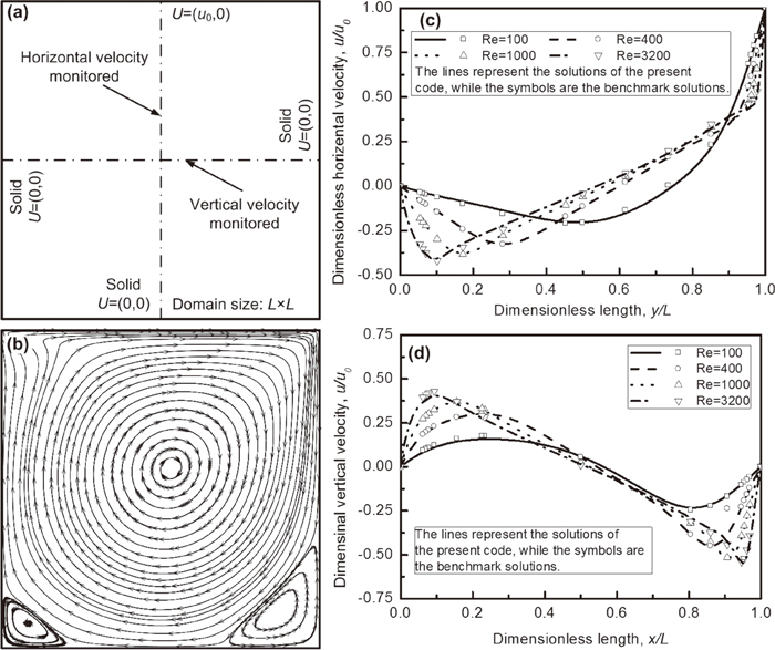
The 2D lid-driven cavity problem is modeled to verify the flow field calculation of the 2D CA-FVM model with benchmark solutions.45,46,47) A square domain with the size of L2 is employed to carry out the simulation. Except for the top boundary with a given horizontal velocity, u0, which is the function of Reynolds number, Re, other boundaries of the 2D domain are regarded as solid walls with no-slip conditions, as shown in Fig. 1(a). For quantitative comparison with the classical benchmark solution, both the horizontal velocity at the vertical centerline and the vertical velocity at the horizontal centerline of the cavity are monitored. Note that the dimensionless velocity and length are used by scaling the relative quantities with the u0 and L, respectively. When the flow reaches steady state, the dimensionless solutions for lid-driven cavity problem are obtained for different Re. Figure 1(b) shows the stream line of the flow in the cavity at Re=1000. It can be noted that in the lid-driven cavity, a large vortex is formed near the center of the cavity and leans to the right. Another interesting phenomenon is that there are two vortexes near the bottom corners and the left one is smaller than the right one. This flow pattern of the lid-driven cavity is consistent with the classical benchmark solution.45,46) Also a quantitative comparison between the calculated flow velocity and the classic benchmark solutions is carried out, as Re is 100, 400, 1000 and 3200, respectively. Figures 1(c) and 1(d) respectively show the calculated dimensionless velocities along the horizontal and vertical direction. It is notable that the trends of the calculated dimensionless velocities agree well with the classic benchmark solutions, when the Re increases from 100 to 3200. It means that the 2D CA-FVM is capable of quantitatively characterizing the flow pattern of lid-driven cavity.
In our previous works,40,41,48) preliminary validation of the 2D CA-FVM model for dendritic growth controlled by pure solute diffusion in a static melt has been performed with the comparison of the classical LGK analytical model,49,50) and a good agreement has been obtained over a small range of low undercooling. It should be mentioned here that the capillary effects are neglected and thus the selection parameter, σ0*, which is vital for the unique determination of the steady-state dendrite shape, is set to be constant and equal to 1/4π2, according to the marginal stability criterion.51) However, the microscopic solvability theory52) highlights the crucial role of the surface energy and the crystalline anisotropy in the shape preservation of steady-state dendritic growth and points out the selection parameter is a function of the anisotropy parameter ε. For the case of ε=0.04 used in the present study, the corresponding σ0* for two dimensions is 0.1785, according to the linearized solvability theory proposed by Barbieri and Langer.53)
In order to validate the 2D CA-FVM model for free dendritic growth in a undercooled alloy melt, a nucleus with the composition of kC0 and the crystallographic orientation of 00 with respect to the horizontal direction is assigned at the center of the square domain with isothermal undercooling melt of Fe-0.82 wt%C binary alloy. The domain is meshed into 300 × 300 cells with size of 1 μm, which is proved to be fine enough to eliminate the mesh dependency of the 2D CA-FVM model.41) Without another specification, this kind of cell configuration and domain size are adopted in the following cases for the simulation of the equiaxed dendritic growth both with and without fluid flow. Meanwhile, for description convenience, the dimensionless composition, undercooling, tip radius, and tip velocity are used by scaling the relative quantities with C0, ΔT0=|m|(1−k0)C0/k0, d0=Γ/ΔT0 and V0= Dl/d0, respectively, where ΔT0 is the unit undercooling, V0 is the unit velocity and d0 is the solutal capillary length.
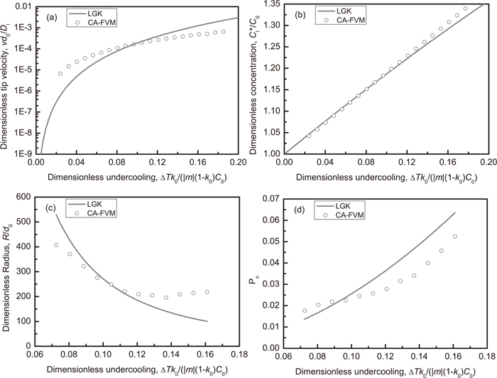
Figure 2 shows the comparison of the steady-state dendritic growth parameters predicted by the 2D CA-FVM model and the classic LGK model, respectively. It can be seen that the trends of the steady-state tip velocity, the equilibrium composition, the tip radius and the solutal Péclet number, Pc=VR/(2D), as a function of undercooling are well predicted by the 2D CA-FVM model and consistent with the LGK predictions. Especially, as the dimensionless undercooling is within the range of 0.08–0.12, the calculated steady-state dendritic growth parameters by the 2D CA-FVM model agree well with the LGK predictions. Nevertheless, when the dimensionless undercooling is out of this range, some discrepancies for the dendritic growth parameters are observed. When the undercooling is lower, the steady-state tip velocity and solutal Péclet number predicted by the 2D CA-FVM model are a little bigger than the LGK predictions, whereas the steady-state tip radius and concentrations predicted by the 2D CA-FVM model are a little smaller than the LGK predictions. When the undercooling is higher, the calculated steady-state tip radius and concentrations are larger than the LGK predictions, whereas the steady-state tip velocity and solutal Péclet number are smaller than the LGK predictions. But in all, a very good agreement between the numerical predictions and the LGK predictions for the steady-state dendritic growth parameters are obtained in a relatively low undercooling range.
Bouissou and Pelcé54) extended the theory of Ivantsov to consider the effect of forced flow on dendritic growth in the small Reynolds number regime and obtained the 2D Oseen-Ivantsov solution for a paraboloidal dendrite tip in a convectional undercooled melt with the flow direction opposite to the growth direction. The 2D Oseen-Ivantsov solution, which determines the relationship between the growth Péclet number, Pc, and the flow Péclet number, Pf=UR/(2D), can be expressed as followings:
|
Ω=
P
c
exp(
P
c
-
P
f
)
∫
1
∞
exp{
-
P
c
η+
P
f
[
2+
∫
1
η
g(
ζ
)
ζ
d
ζ
-η
]
}
dη
η
| (17) |
|
Ω=
C
l
*
-
C
0
C
l
*
(
1-
k
0
)
| (18) |
|
g(
ζ
)
=
ζ
erfc(
Reζ
/2
)
+
2/
πRe
[
exp(
-Re
/2
)
-exp(
-Reζ
/2
)
]
erfc(
Re
/2
)
| (19) |
where Ω is the solutal supersaturation,
Re is the Reynolds number,
Re=
uR/
ν, and
u is the flow velocity.
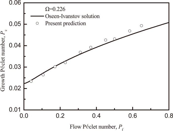
In order to validate the 2D CA-FVM model for simulating the dendritic growth with fluid flow via the comparison of the numerical results against the Oseen-Ivantsov solution, the simulation conditions should be consistent with the prerequisites for Oseen-Ivantsov solution, where the thermal-controlled dendritic growth in a pure substance is a two-sided diffusion problem, and thus, for the isothermal solute-controlled dendritic growth, the solid/liquid solute diffusivities should be assumed to be equal in order to satisfy the two-sided diffusion problem. Meanwhile, a nucleus with a crystallographic orientation of 00 with respect to the horizontal direction was assigned at the center of the calculation domain and the forced flow with a constant dimensionless underooling of 0.0967 was introduced along the horizontal direction. For this case, the simulated steady-state tip equilibrium composition, Cl*/C0, and the dimensionless supersaturation, Ω, are 0.175 and 0.226, respectively. Figure 3 shows the comparison between the calculated results and the Oseen-Ivantsov solutions for the growth Péclet number, Pc, as a function of the flow Péclet number, Pf. It can be noted that the calculated results agree well with the Oseen-Ivantsov solutions.
4. Results and Discussion
In this section, more numerical simulations of the equiaxed dendritic growth and the columnar dendritic growth with fluid flow were performed in order to address the further capabilities of the 2D CA-FVM model.
4.1. Equiaxed Dendritic Growth
A numerical simulation was performed for the single equiaxed dendritic growth in a constant undercooled melt with fluid flow. At the beginning of the simulation, a nucleus with the composition of kC0 and the crystallographic orientation of 00 with respect to the horizontal direction is placed at the center of the square calculation domain. The cells surrounding the nucleus are assigned as interface cells and the others are assigned as liquid cells with the initial composition of C0. The imposed fluid with the same undercooling and composition as the melt directly flows into the domain from the left boundary and leaves with full development at the right boundary. The top and bottom boundary are assumed to be symmetrical.
For comparison, the dendritic growth in a static melt with dimensionless undercooling of 0.048 was firstly simulated and the dendrite morphologies and solute profiles of Fe-0.82 wt%C binary alloy at different times are shown in Fig. 4. It is notable that for the solute-driven dendritic growth in a constant undercooled melt without fluid flow, the dendrite morphology and solute profile exhibit the symmetric features.

Figure 5 shows the dendrite morphologies, solute profiles and flow field of the dendritic growth of Fe-0.82 wt%C alloy under the forced melt flow with dimensionless undercooling of 0.048 and flow velocity of 0.003 m/s for different holding times. It should be mentioned here that one uniform flow vector, which only represents the flow direction but not the relative flow strength, is plotted in every 10 × 10 cells for a clear visualization, and streamlines are overlapped in order to show the flow pattern. It is obvious that the fluid flow has a significant impact on the dendrite morphologies and solute profiles. The solute is washed away from the upstream region to the downstream region in the presence of forced flow from the left to right, resulting in the solute enrichment and lower concentration gradient in the downstream region. According to the control equation of dendritic growth, Eq. (13), the high concentration gradient promotes tip velocity of dendritic growth controlled by the pure solute diffusion. Consequently, the dendrite trunk in the upstream grows significantly faster and coarser than that in the downstream region, resulting in an asymmetrical dendrite morphology. In addition, another interesting phenomenon should be noted that there are four inward vortexes at the foot of the dendrite trunk in the presence of fluid flow and the vortex size gradually increases with the dendritic growth, which means that the blockage of dendritic trunk on the fluid flow becomes more and more significant with the dendritic growth.
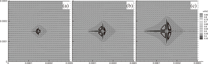
Figure 6 shows the tip velocity of dendritic growth of Fe-0.82 wt%C alloy with and without fluid flow as a function of time. It is notable that no matter the fluid flow is imposed or not, the dendritic growth shows a high speed period at the initial time and rapidly approaches to steady-state period with a relatively low speed. However, the fluid flow significantly affects the tip growth velocity. The steady-state tip velocities of the upstream dendrite trunk, which is opposite to the fluid flow direction, and the perpendicular dendrite trunk, which is perpendicular to the fluid flow direction, are obviously higher than that without fluid flow, because the rejected solute in front of the dendrite tip is washed away by the fluid flow and thus a thin solute boundary with high concentration gradient both at the upstream tip and the perpendicular tip is formed, which is benefit for the dendritic growth. Owing to the relative angle difference between the dendrite trunk growth direction and fluid flow direction, the rejected solute at the upstream tip is much easier to be washed away by fluid flow than that at the perpendicular tip, resulting in a higher tip speed for the upstream tip. Moreover, when the upstream tip approaches the side boundary, the wash effect becomes more significant and the tip growth velocity increases, which was consistent with the phenomena reported by Zhu et al.24) This phenomenon may be caused by the small domain size and can be released by the calculation domain enlargement. Because of the enriched solute at the downstream region in the presence of fluid flow, the downstream tip growth, which has same direction with fluid flow, is inhibited and the steady-state tip growth velocity of the downstream dendrite trunk is obviously lower than that without fluid flow.
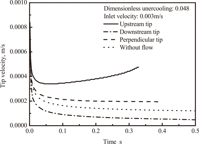
Figure 7 shows the effect of the inlet velocity of the forced flow on the dendritic growth of Fe-0.82 wt%C binary alloy in the undercooled melt with dimensionless undercooling of 0.048 for same holding time of 0.2 s. It can be seen that with the increase of the inlet velocity, the rejected solute in the upstream region is much easier to be washed away and enriched in the downstream region, resulting in accelerating the upstream tip and perpendicular tip growth and inhibiting the downstream tip growth. Meanwhile, the vortexes at the foot of the dendrite trunk are enhanced and the asymmetries of the dendrite morphology and solute profile become more and more significant with the increase of inlet velocity of the forced flow.
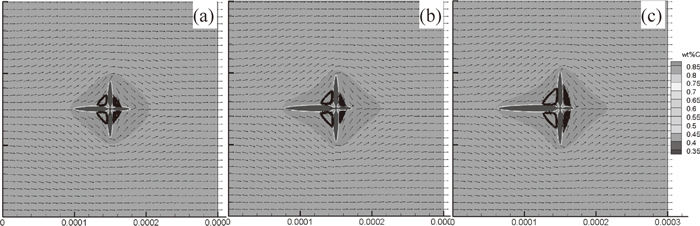
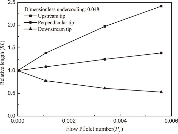
In order to quantitatively determine the effect of flow intensity on the dendritic growth, the relative length (RL) is expressed as the ratio of the dendrite trunk length with and without fluid flow. Figure 8 shows the effect of the flow Péclet on the relative length of equiaxied dendrite with and without fluid flow. It is notable that in the presence of fluid flow, the relative lengths of the upstream tip and perpendicular tip are larger than 1.0, which means that the fluid flow promotes the dendritic growth of the upstream tip and perpendicular tip. But the acceleration growth intensity of the upstream tip induced by the fluid flow is much more significant than that of the perpendicular tip growth. Whereas, the relative length of the downstream tip is smaller than 1.0, which means that the dendritic growth in the downstream region is inhibited. In addition, with the increase of the flow Péclet number, the relative lengths of the upstream tip and perpendicular tip continuously increase, whereas the relative lengths of the upstream tip show a continuous decrease trend.
Numerical simulation is performed for the columnar dendritic growth of Fe-0.82 wt%C binary alloy in the lid-driven cavity. The calculation domain is divided into 408 × 408 cells with a cell size of 1 μm. Heat is extracted from the bottom side of the calculation domain with a constant heat flux q=1.0 MWm−2, and the other three sides of the calculation domain are adiabatic. The forced flow is introduced by imposing a horizontal advection at the top side of the domain, and the other three sides are wall boundary. At the beginning of simulation, the whole calculation domain is initialized with homogenous liquidus temperature of the alloy and eight nuclei with the same crystallographic orientation of 00 with respect to the horizontal direction are assigned at the bottom side with same spacing.
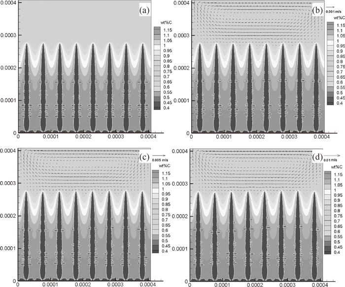
Figure 9 shows the effect of the flow intensity on the columnar dendrite morphology, solute field and flow field in the lid-driven cavity. It can be seen that without fluid flow, the columnar dendrites develop a symmetrical morphology under the unidirectional solidification condition and the solutes are rejected from the solid/liquid interface and enriched between the columnar dendrite trunks with the columnar dendritic growth. Thus, a symmetrical solute profile is produced and inversely controls the symmetrical dendritic growth without fluid flow. As the horizontal advection is introduced at the top of domain, a circulation flow is produced ahead of the dendrite array in the lid-driven cavity, and has a wash effect on the solute distribution at the solid/liquid interface, resulting in the asymmetrical solute profile. Thus, an asymmetrical dendrite morphology is produced in the asymmetrical solute profile induced by the imposed flow. And another interesting phenomenon is that the circulation flow has an impact on the stability of the solid/liquid interface and facilitates the side branch of the dendrite trunk edge which faces to the incoming flow. With the increase of the flow intensity, the side branch of the dendrite is more favorable and the asymmetry of the dendrite morphology and solute profile is more significant. In addition, the rejected solute is also mainly enriched between the columnar dendrite trunks in the presence of fluid flow, because the flow in the inter-dendrite region is weak and hard to wash away the rejected solute.
5. Conclusion
In the present study, the 2D CA-FVM model, which was proposed for simulating the dendritic growth in the presence of fluid flow in our previous study,40) has been extensively verified via the comparison between the numerical predictions and the classical analytical solutions, namely, solution for lid-driven cavity problem, LGK model and Oseen-Ivantsov solution. Meanwhile, numerical simulations of the equiaxed dendritic growth and the columnar dendritic growth in the presence of fluid flow have been performed to further demonstrate the model capability. The main conclusions are summarized as follows:
(1) Model validation shows that a good agreement between the numerical predictions and the analytical solutions is reached for the fluid flow in the lid-driven cavity and the free dendritic growth in a static undercooled melt and convectional undercooled melt. For the lid-driven cavity problem, the flow pattern is well predicted and the calculated velocities agree well with the classic benchmark solutions, when the Re increases from 100 to 3200. For the free dendritic growth of Fe-0.82 wt%C alloy in the static undercooled melt, the predicted tip velocity, solute concentration, tip radius and solutal Péclet number of steady-state dendritic growth are compared with the LGK predictions and a good agreement is obtained in a relatively low undercooling range. Moreover, for the dendritic growth of Fe-0.82 wt%C alloy in the convectional undercooled melt, the predicted trend of the growth Péclet number, Pc, as a function of the flow Péclet number, Pf, is quantitatively coincident with the Oseen-Ivantsov solution.
(2) Numerical simulations of the equiaxed dendritic growth and the columnar dendritic growth with fluid flow have been carried out and the results show that the fluid flow has a significant impact on the dendrite morphologies and solute profiles. For the equiaxed dendritic growth of Fe-0.82 wt%C alloy with fluid flow, the solute is washed away from the upstream region to the downstream region, resulting in accelerating the dendritic growth of the upstream tip and perpendicular tip and inhibiting the dendritic growth of the downstream tip. Thus, the asymmetrical morphology and solute profile of the equiaxed dendrite are developed in the undercooled melt with fluid flow and become more and more serious with the increase of the flow Péclet number. Moreover, for the columnar dendritic growth of Fe-0.82 wt%C alloy in the lid-driven cavity, the circulation flow induced by the horizontal movement of lid at the top affects the stability of the solid/liquid interface and facilitates the side branch of the dendrite trunk edge which faces to the incoming flow. Also the columnar dendrite develops an asymmetrical morphology and the effect of the fluid flow becomes more and more significant with the increase of the flow Péclet number.
Acknowledgements
The authors gratefully acknowledge the financial support of National Natural Science of China (No. 51404062, U1560208), Specialized Research Fund for the Doctoral Program of Higher Education of China (No. 20130042120042), Outstanding Talent Cultivation Project of Liaoning Province (No. 2014029101) and Fundamental Research Funds for the Central Universities (No. N150204018).
References
- 1) J. Campbell: Castings, 2nd ed., Elsevier, Oxford, (2003), 320.
- 2) Y. Ebisu: Metall. Trans. B, 42B (2011), 341.
- 3) T. Campanella, C. Charbon and M. Rappaz: Metall. Trans. A, 35A (2004), 3201.
- 4) J. H. Ma, J. Li, Y. L. Gao, L. X. Jia, Z. Li and Q. J. Zhai: Met. Mater. Int., 15 (2009), 603.
- 5) M. C. Flemings: ISIJ Int., 40 (2000), 833.
- 6) R. H. Mathiesen and L. Arnberg: Acta Mater., 53 (2005), 947.
- 7) M. Yonemura, T. Osuki, H. Terasaki, Y. Komizo, M. Sato and H. Toyokawa: Mater. Trans., 47 (2006), 2292.
- 8) H. Nguyen-Thi, L. Salvo, R. H. Mathiesen, L. Arnberg, B. Billia, M. Suery and G. Reinhart: Comp. Rend. Phys., 13 (2012), 237.
- 9) M. Asta, C. Beckermann, A. Karma, R. Napolitano, M. Plapp, G. Purdy, M. Rappaz and R. Trivedi: Acta Mater., 57 (2009), 941.
- 10) X. Tong, C. Beckermann and A. Karma: Phys. Rev. E, 61 (2000), R49.
- 11) C. Beckermann, H. J. Diepers, I. Steinbach, A. Karma and X. Tong: J. Comput. Phys., 154 (1999), 468.
- 12) Y. Lu, C. Beckermann and J. C. Ramirez: J. Cryst. Growth, 280 (2005), 320.
- 13) X. Tong, C. Beckermann, A. Karma and Q. Li: Phys. Rev. E, 63 (2001), 061601.
- 14) J.-H. Jeong, N. Goldenfeld and J. A. Dantzig: Phys. Rev. E, 64 (2001), 041602.
- 15) J.-H. Jeong, J. A. Dantzig and N. Goldenfeld: Metall. Mater. Trans. B, 34B (2003), 459.
- 16) C. W. Lan, C. M. Hsu, C. C. Liu and Y. C. Chang: Phys. Rev. E, 65 (2002), 061601.
- 17) C. W. Lan, C. M. Hsu and C. C. Liu: J. Cryst. Growth, 241 (2002), 379.
- 18) C. W. Lan and C. J. Shih: J. Cryst. Growth, 264 (2004), 472.
- 19) C. C. Chen, Y. L. Tsai and C. W. Lan: Int. J. Heat Mass Tran., 52 (2009), 1158.
- 20) Z. P. Guo, J. Mi, S. Xiong and P. G. Grant: Metall. Mater. Trans. B, 44B (2013), 924.
- 21) N. Al-Rawahi and G. Tryggvason: J. Comput. Phys., 180 (2002), 471.
- 22) N. Al-Rawahi and G. Tryggvason: J. Comput. Phys., 194 (2004), 677.
- 23) Y. H. Shin and C. P. Hong: ISIJ Int., 42 (2002), 359.
- 24) M. F. Zhu, S. Y. Lee and C. P. Hong: Phys. Rev. E, 69E (2004), 061610.
- 25) M. F. Zhu, T. Dai, S. Y. Lee and C. P. Hong: Comput. Math. Appl., 55 (2008), 1620.
- 26) M. F. Zhu, T. Dai, S. Y. Lee and C. P. Hong: Sci. China Ser. E, 48 (2005), 241.
- 27) D. R. Liu, E. J. Guo, L. P. Wang, F. W. Kang and Q. Lan: Int. J. Cast Metal. Res., 20 (2007), 254.
- 28) D. M. Li, R. Li and P. W. Zhang: Appl. Math. Model., 31 (2007), 971.
- 29) L. Yuan, P. D. Lee, G. Djambazov and K. Pericleous: Int. J. Cast Metal. Res., 22 (2009), 204.
- 30) L. Yuan and P. D. Lee: Model. Simul. Mater. Sci. Eng., 18 (2010), 055008.
- 31) Y. F. Shi, Q. Y. Xu and B. C. Liu: Acta Phys. Sin., 60 (2011), 126101.
- 32) X. F. Zhang and J. Z. Zhao: Acta Metall. Sin., 48 (2012), 615.
- 33) D. K. Sun, M. F. Zhu, S. Y. Pan and D. Raaba: Acta Mater., 57 (2009), 1755.
- 34) D. K. Sun, M. F. Zhu, S. Y. Pan, C. R. Yang and D. Raabe: Comput. Math. Appl., 61 (2011), 3585.
- 35) M. F. Zhu, D. K. Sun, S. Y. Pan, Q. Y. Zhang and D. Raabe: Model. Simul. Mater. Sci. Eng., 22 (2014), 034006.
- 36) H. Yin, S. D. Felicelli and L. Wang: Acta Mater., 59 (2011), 3124.
- 37) B. Jelinek, M. Eshraghi, S. Felicelli and J. F. Peters: Comput. Phys. Commun., 185 (2014), 939.
- 38) K. Reuther and M. Rettenmayr: Comput. Mater. Sci., 95 (2014), 213.
- 39) W. Wang, P. D. Lee and M. McLean: Acta Mater., 51 (2003), 2971.
- 40) W. L. Wang, S. Luo and M. Y. Zhu: Comput. Mater. Sci., 95 (2014), 136.
- 41) S. Luo and M. Y. Zhu: Comput. Mater. Sci., 71 (2013), 10.
- 42) M. F. Zhu and D. M. Stefanescu: Acta Mater., 55 (2007), 1741.
- 43) L. Beltran-Sanchez and D. M. Stefanescu: Metall. Mater. Trans. A, 34A (2003), 367.
- 44) L. Beltran-Sanchez and D. M. Stefanescu: Metall. Mater. Trans. A, 35A (2004), 2471.
- 45) O. Botella and R. Peyret: Comput. Fluids, 27 (1998), 421.
- 46) C. H. Bruneau and M. Saad: Comput. Fluids, 35 (2006), 326.
- 47) U. Ghia, K. N. Ghia and C. T. Shin: J. Comput. Phys., 48 (1982), 387.
- 48) W. L. Wang, S. Luo and M. Y. Zhu: Metall. Mater. Trans. A, 46A (2015), 396.
- 49) J. Lipton, M. E. Glicksman and W. Kurz: Mater. Sci. Eng., 65 (1984), 57.
- 50) J. Lipton, M. E. Glicksman and W. Kurz: Metall. Mater. Trans., 18 (1987), 341.
- 51) J. S. Langer and J. Müller-Krumbhaar: J. Cryst. Growth, 42 (1977), 11.
- 52) R. Trivedi and W. Kurz: Int. Mater. Rev., 39 (1994), 49.
- 53) A. Barbieri and J. S. Langer: Phys. Rev. A, 39A (1989), 5314.
- 54) P. Bouissou and P. Pelcé: Phys. Rev. A, 40A (1989), 6673.