Abstract
Interaction of solidified shell and fluid flow inside the mold cavity governs the quality in the continuous slab casting of steel. A careful mathematical model can reveal the phenomena at play to take corrective action for better quality and productivity of the caster. These phenomena include turbulent flow in the nozzle and mold, heat transfer and solidification, the transport of bubbles and inclusion particles, multi-phase flow phenomena, the effect of electromagnetic forces, interfacial phenomena, interactions between the steel surface and the slag layers, the transport of solute elements and segregation etc. Substantial development has been done across the world in this direction during past few years. This paper reviews recent progress in modeling the thermo-fluid aspect of a steel caster.
1. Introduction
Continuous slab casting of steel involves delivery of the liquid metal through a submerged entry nozzle into a water cooled mold where solidification process begins. Various complex phenomena1,2) including thermo-fluid are at play within the mold to govern the quality of the cast slabs. Understanding of each phenomenon is important to have right casting conditions. In this direction, lots of efforts have been made around the globe in past few decades through mathematical modeling. Impressive growth in the area of computer has aided to decode the complex caster. The progress has made it possible to take upto 5 million grids.3)
Highly turbulent fluid flow within the mold cavity is further entangled by presence of multiphase i.e. argon bubbles, overlying mold flux/slag, and non-metallic inclusion particles along with thermal effects. Superheat dissipation is coupled with the prevailing fluid flow and so is solidification progress in the mold. Interaction of fluid flow and solidification leads to washing effect,4) hook formation, turbulence near mushy region and its growth. These interactions affect the as-cast structure mainly in equiaxed zone,5) segregation, and natural solutal convection. These interactions take place in at various geometrical scales like dendritic scale where microsegregation is prevalent; here local solutal convection and steel-grade wise dendritic solidification growth characteristics governs the phenomena. This scale modeling falls in purview of “Phase change modeling”. Mushy region where heat and momentum transfer is governed by bulk flow characteristics with boundaries modified by a porous kind of dynamic structure. Modeling various scale phenomena simultaneously is a daunting task posed with many numerical methodological challenges. Mapping of superheat dissipation in the mold cavity is possible even without modeling the solidification.6) Though, many techniques have been developed to model the fluid flow and solidification in a coupled manner. The solidification modeling must capture the evolving position of the solidification front. To resolved this, a moving grid numerical methodology based on the classical Stefan formulation,7,8) i.e. a temperature-based heat transfer equation is needed. This asks for detailed numerical treatment in the vicinity of the phase change, conditions on temperature, velocity and latent heat evolution. This poses a difficult numerical solution as deforming grids or transformed co-ordinate systems are required to account for the position of the phase front. A fixed grid numerical solution is “enthalpy-porosity formulation”.9,10,11) This approach has been the back-bone for the thermo-fluid modeling of steel casters and has many variations of the formulation. The energy equation is enthalpy based rather than the temperature. This approach removes the need to explicitly satisfy conditions at the phase front and is therefore able to directly utilize standard solution procedures for the fluid flow and energy equations without resorting to mathematical manipulations and transformations. The enthalpy formulations account for the latent heat in the energy equation by assigning a nodal latent heat value to each computational cell according to the temperature of the cell.
The modeling on fluid flow side has also needed to capture flow side details to generate more closer to reality understanding/results. Over the periods increasingly complex models are developed to take into account various phenomena at work. Computational rigour has evolved from a symmetry modeling approach12,13,14,15) to full domain16) taking inherent flow asymmetries into account, from 2-dimensional (2D)12) to 3-dimensional (3D)16) modeling approach to correctly implement turbulence, from steady state12,14) modeling to transient16,17) modeling approach to capture chaotic nature of flow, from single phase flow12,15) to multiphase flow17) to take interaction of argon bubbles, overlying slab/mold flux layer along with solutal and thermal convections.
This paper reviews the recent developments in the field of thermo-fluid modeling to unfold building of formidable capability providing insight for improvement of continuous steel slab caster.
2. Superheat Dissipation in the Mold Cavity
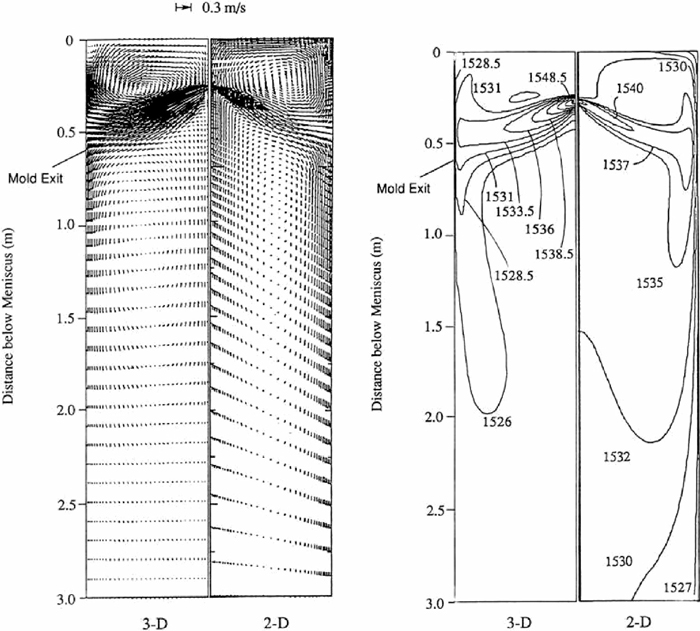
Modeling superheat dissipation18,19,20) requires solving energy equation along with conventional Navier-stokes equation and suitable turbulence models. Najjar13) et al were among the first to model a 2D symmetrical steady state heat transfer, that was in last century. Substantial research was done to understand the superheat dissipation within the mold with simplistic approach without solidification modeling. Here the thermal boundary condition was provided as liquidus solidification temperature i.e. mushy region and shell solidification were left out of computational domain. Thermal buoyancy was excluded. Whereas later Huang13) developed a 3D two fold symmetrical steady state heat transfer through finite volume approach. Importance of wall law implementation in the model was highlighted.21,22) After comparing 2D and 3D results as shown in Fig. 1, necessity for 3D calculations was established. Here thermal buoyancy effect was tried to capture but end up concluding that its effect in upper mold region was negligible on thermo-fluid aspect and thus was excluded for rest of the parametric study. Though a caution was felt that even in mold region like near mushy zone, below the nozzle etc. where Froude number may be lower, natural convection may have a role to play. Shell thickness calculation were done with a separate heat conduction based 1-dimensional (1D) model from superheat dissipation input and was shown to have a good match with shell thickness measurements. Q. Yuan16) improved the model fluid flow calculation by taking mass sink near solidification front into account with transient simulations. The question of extent of computational domain was also addressed by concluding that quarter domain is best avoided as it prevents the jet inherent oscillating and swirling tendencies. Stressing upon importance of turbulence model and grid size, effect of k-ε model with wall-law, low Reynolds (Re) number k-ε model, and Large Eddy Simulation Sub-Grid Scale (LES-SGS) model were evaluated. Das23) advocated about uneven shell due to off-centered Submerged Entry Nozzle (SEN). Zhao24) investigated the detailed turbulent single-phase flow and heat transfer with 3D LES simulation of a slab caster with center plane symmetry. As shown in Fig. 2, large fluctuations were revealed in flow due to anisometric turbulence and its impact on temperature of liquid steel inside mold cavity along with resultant uneven heat transfer rate of order 350 kW/m2 through solidifying shell. They validated their model by thermocouple measurement done in the real caster.
3. Thermal Fluid Flow in the Mold
Modeling fluid flow in presence of heat transfer and solidification was a challenging task given the uncertainties in the wall boundary condition in presence of complex dynamic dendritic structure. Flow near solidification front would behave completely different than that of in bulk liquid region.25) When treating the wall fixed as liquidus, modifying wall roughness was thought of as a solution.13) This calls for solving Navier-Stokes equations with an appropriate turbulence model like low-Re k-ε model and energy equation in temperature24) form as:
|
∂(
T
→
)
∂t
+
∂(
u
i
→
T
→
)
∂
x
i
=
K
ρ
C
p
∂
∂
x
i
(
∂(
T
→
)
∂
x
i
)
+
∂
Q
T
i
∂
x
i
|
Where T denotes temperature, t – time, xi – coordinate, u – velocity, K – thermal conductivity, ρ – reference density, Cp – heat capacity, and QTi represents heat flux source term to take the thermal diffusion due to turbulence into account as:
|
∂
Q
T
i
∂
x
i
=
μ
t
P
r
T
∂
∂
x
i
∂
T
¯
∂
x
i
|
Where μt is eddy-viscosity, PrT is prandtl number valued 0.9 here.
Progressively effect of various important parameter sensitivity is checked by various researchers. Main parameters were wall laws, turbulence models, choice of grid and its coupling with heat transport26,27) etc. Such developed model proved very useful in optimizing the SEN designs.22,28,29) Flow emanating from SEN into mold has been captured by numerous researchers through latest physical modeling techniques like Particle Image Velocimetry (PIV) etc. and have been extensively used as a first hand validation for fluid flow results.24,30,31,32,33,34,35,36)
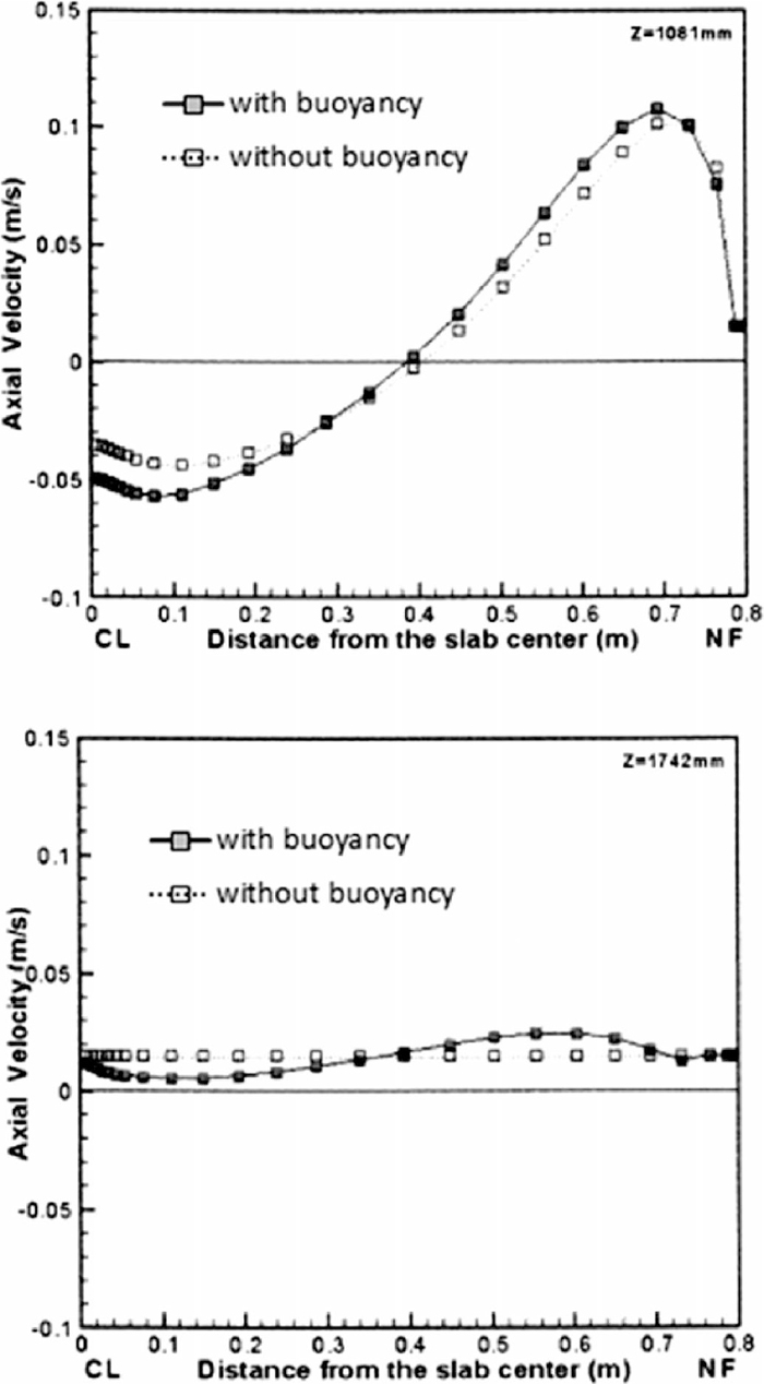
QIU37) developed a validated 3D steady coupled model to resolve the thermal driven buoyancy flow. The importance of inter-dendritic convection was underlined by non-dimensional analysis. In absence of this effect, the recirculation loop may be under predicted by the model.37,38) As shown in Fig. 3, thermal buoyancy role is appreciable especially in sub-mold region.17) It was demonstrated that thermal fluid flow will have a stabilizing effect on lower recirculating flow below the SEN. Discharge jet out of the SEN has tendency to diffuse upward as buoyancy forces rise up part of the steel stream. The extent of two forces are compared as in Fig. 4. This shows that buoyance forces cannot be neglected in later part of the discharge jet. Boussinesq model has been widely used for density variation.

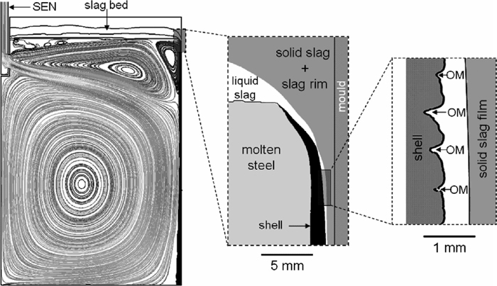
The nature of sub-meniscus flow in the presence of overlying flux is important from the initial solidification point of view. The flow may decide the fate of mould flux effectiveness and formation of a hook and associated defects23,39,40,41) (Fig. 5). The heat transfer for sufficient melting of mold flux depends upon the undercurrent velocity. Whereas an unstable and oscillating jet may unsettle the meniscus dynamics and produce a vortexing phenomenon.42) Various fluid flow conditioners have been investigated to overcome the problem.43) Thermal differences might make the situation worse as cooler steel comes over hotter steel. Significant modeling efforts have been made to resolve the meniscus region by a Volume Of Fluid (VOF) approach.44,45,46,47) The standing wave has been observed in water models and actual caster. The shape of these wave keeps fluctuating depending upon flow in the mold cavity. The wave height and frequency increases with increase of casting speed. Though an electromagnetic force can be applied to minimize these harmful effects48,49,50,51) as it may reduce sub-meniscus velocity by 20% and its fluctuation by 60%.52)
The next challenge was to incorporate multiphase and multi-physics into the molten metal flow model to take argon gas injection in SEN and static magnetic-field into account.49,53) Though these were simplistic approach to take effect of argon bubbles on the fluid flow based on variation of the density of the molten metal. Recently, to model argon bubbles trajectories a Discrete Phase Model (DPM) + VOF approach was developed taking slag-metal interface into account.44) It was concluded that proper implementation of drag law and turbulence model is required for a better similarity with the real situation. In real situation, it is a distribution of bubble size varying mainly from 1–5 mm as revealed by various calculations and bubble captured in real caster54,55,56,57) due to bubble breakup and coalescence phenomena constantly occurring within the mold cavity. Thus the mathematical calculation may take this into account as different bubble size yields differing results in terms of sub-surface velocity. The calculation so far have been based on a single bubble diameter. Smaller bubbles pose a quality threat as they might travel up to solidifying front and get captured while bigger bubbles floats up quickly to disturb the meniscus. Cho52) simulated a sub-1 mm bubble size along with LES model to include a detail turbulence calculation. A strong coupling between the phases revealed that the jet wobbling influences transient argon gas distribution and the location of jet impingement on the narrow Face. In absence of a solidification modeling implementation of a mass sink term has evolved as a modeling practice to predict flow more accurately near walls.52) The coupling between the two phases also produces single roll and double flow pattern on varying casting conditions33,58) recommending careful choice of operating conditions based argon gas flow rate vis-à-vis SEN submergence depth and molten metal through. Another approach to model argon bubbles is an Eulerian–Eulerian (EE) for coupling of two phases.59)
Non-metallic inclusion as a another phase in steel is another worry for a slab caster researcher. The fluid flow inside mold cavity along with solidifying front decide fate of a inclusion particle and therefore steel cleanliness. Evaluation of the path of the inclusion is necessary to make any prediction about fate of the inclusion as whether it is going to be floated up or is going to be caught on solidifying front. A particle momentum equation along with suitable drag law is solved by integrating the equation of motion to correctly predict the particle path.60) Ho29) investigated about use of a rotated port SEN for better steel cleanliness. The flow analysis was based on a steel residence time indicator.
4. Shell Growth through Solidification
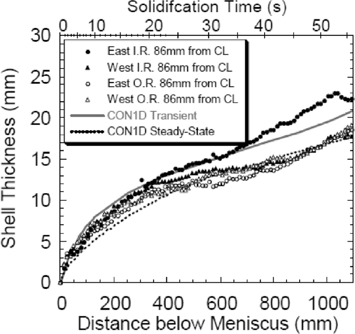
Modeling solidification in a caster involves a understanding at various scales, phases, and thermal zones as liquid-solid phase change occur over a temperature range. Shell thickness evolution as shown in Fig. 6 along the strand length is coupled with fluid flow in mold cavity5,17) interaction with other phases present like inclusion and gas along with varying thermal properties of the solidified shell itself. Microscopically, solidification progress is dendritic in nature61) but become a large problem to simulate the caster. Macroscopically, solidification progress can be viewed as liquid region, mushy region where solidification fraction varies from 0 to 1, and fully solidified shell. The analysis of thermo-fluid phenomena in slab caster from an industrial point of view generally requires a macroscopic solidification modeling. Caster solidification models has progressed from the times of uncoupled solidification only analysis62,63,64,65) to coupled fluid flow solidification problems.66) Modeling treatment of mushy region was key to these developments. This requires a detailed information of temperature field that is generated from energy equation. Initially, a temperature base energy equation was employed along with deforming grids to track moving liquid-solid interface.67) An alternative approach based on enthalpy formulation was proposed by Voller.9,10,11) This made a case for fixed grid solution without an explicit condition on the heat flow at the liquid-solid interface. The issue of arriving at zero velocity condition as the liquid turns to solid was solved by two ways one by varying the viscosity68) and second by treating the mushy region as pseudo porous media with a varying porosity. This gave rise to a “Darcy” source term in momentum equation as:
|
∂(
ρ
u
→
)
∂t
+∇.(
ρ
u
→
u
→
)
=-∇P+∇.(
μ
e
∇
u
→
)
+ρ
g
→
(
β
T
(
T-
T
ref
)
)
+
S
→
mon
|
While the source term here is defined as:
|
S
→
mon
=-
μ
l
K
.(
u
→
-
u
→
s
)
|
K, the permeability for the steel in the mushy region is defined as function of the solid fraction and the secondary dendrite arm spacing.69,70) A Carman-Koseny equation based relation is mostly adapted:
|
μ
l
K
=
C
(
1-
f
l
)
2
(
f
l
3
+b
)
|
where
C is morphology link constant
71) and b is introduced to avoid division by a zero.
While energy equation takes form in terms of enthalpy:
|
∂(
ρ
H
→
)
∂t
+∇.(
ρ
u
→
H
→
)
=∇.(
k ∇
T
→
)
+
S
→
e
|
Where source term was defined as9)
|
S
→
e
=-
∂(
ρ
ΔH
→
)
∂t
-∇.(
ρ
u
→
ΔH
→
)
|
For a caster case where solidified shell is moving it becomes72)
|
S
→
e
=-∇.(
ρ
f
l
u
→
ΔH
→
)
-∇.(
ρ
f
s
(
u
→
-
u
→
s
)
ΔH
→
)
|
The technique has been used to model the thermo-fluid phenomena in numerous application like bloom,73) billet,74) slab caster,75) thin slab caster,76) twin roll casting,77) strip casting78,79) etc. Thomas1,80,81,82) has pioneered the fluid flow and solidification calculations to validate and demonstrate the accuracy of such a mechanistic models. The careful use of turbulence model along with suitable mesh size was mentioned as a high-Re k-ε turbulence model needs y+ is excess of 30 whereas a low-Re k-ε turbulence model requires a y+ less than 1. A good match was demonstrated with breakout shell measurements with predicted shell thickness. Ha83) utilized the above methodology to study the solidification phenomena with ElectroMagnetic BRake (EMBR). The interactions of fluid flow with solidified shell was captured well and effect of EMBR was assessed as having a smoother solidified surface pattern (Fig. 7). SEN design is another aspect that can be resolved through this kind of models.72) Solidification progress also changes the flow pattern inside the cavity in an effective ways through thermal buoyancy.37,84) The effect of thermal buoyancy is obvious in the sub-mold zone but it also becomes an important factor even in the regions of strong forced convection near liquidus temperature as it induces a turbulence flow. Consequently, it also affects the temperature distribution of the slab. Thus a careful consideration of buoyancy effect is a must in the thermo-fluid calculation of the slab caster. These effect becomes even more important when investigating the particle movement inside the mold in presence of solidifying shell.85)
Bellet86) extended the mushy zone modeling concept to capture the mushy zone fluid flow as slab passes through two consecutive rolls showing a bulging. Tambunan87) used a moving quarter 2D slice at casting speed to model the solidified shell thickness profile by using the enthalpy-porosity technique. Shamsi88) modeled quadrant of a commercial slab caster considering steady state. A realistic use of heat transfer coefficient is important to rightly predict the real situation temperature and shell thickness. Measurement of shell profile in the caster is possible with injection of FeS and subsequently printing its presence in solidified slab and provide with very good data to cross check the predictions. It is possible to correlate prevalent cooling rate through appropriate measurement of primary and secondary dendrite spacing89) and provides a good input for modeling of shell thickness.
One aspect of the thermo-fluid modeling is thinning of solidified shell due to convection effect of superheated liquid steel in the mold.24,90) Shell thinning is affected by number of caster parameters like steel superheat, nozzle design, multiphase flow, non-uniform mold cooling, type of mould powder etc. Wang91) analyzed mold data for non-uniform mold cooling by assessing heat flux variation from mold thermocouple data by employing an inverse heat transfer concept and subsequently using the derived data to demonstrate its effect on shell thickness. It was stressed to use actual derived heat flux for the shell thickness calculation for realistic predictions. Such calculations can also be extended to optimize the mould taper.92)
Bastida84) suitably modified the enthalpy-porosity equations to accommodate presence of multiphase including air for free surface and infiltration of mould flux. VOF method with mixture properties proportional to phase present in the cell was used. With the model, effect of subtle changes in nozzle design on temperature and solidified shell profile was assessed. Shell thinning effect due to curved nature of mold was quantified in order to prevent a break out situation. Lopez39,40,41,44,45,93) extended the shell growth modeling in presence of multiphase and included real caster dynamics of slag infiltration with oscillation. The model revealed the initial solidification mechanism and formation of oscillation marks. A very fine mesh of 0.1 mm was utilized to capture initial shell formation and nearby flow. Though to save on computational resources a 2D modeling was adapted. One complex case was done in about 120 h on dual core computer.
Solidification modeling in presence of fluid flow has evolved to great extent but still few areas are yet to be explored like suitable turbulence model in presence of a mushy region especially in porous type formulation.25,94) Variation of solid fraction throughout the mushy region is another parameter that requires help from experimental study and fundamental phase field modeling. Various profiles has been assumed varying from linear with respect to prevalent temperature to exponentially varying.69) Belhamadia95) demonstrated incorporation of different thermo-physical properties into the enthalpy-porosity technique and showed improved results where the properties differ significantly like in case of water.
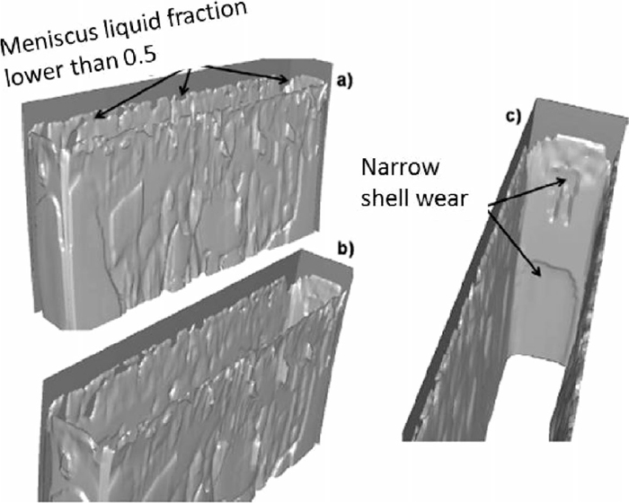
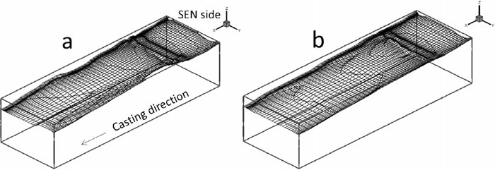
Recently, Du96) extended the computations to also predict porosity and macrosegregation in the continuously cast product using the same concept of fluid flow, heat transfer, and phase change modeling. Hernandez17) investigated the interaction of fluid flow in the mold on initial shell growth. A multiphase approach with enthalpy-porosity method was employed to take the free meniscus and overlying slag layer. Due to curved nature of slab caster mold, the fluid flow effect on front and back face of the slab is not equal. This creates different extent of thermo-fluid interactions. It was revealed that inner radius is more prone to this interaction than the outer radius as shown in Fig. 8.
With the similar thermo-fluid modeling approach, efforts97) are on for extending the models for thermo-fluid-mechanical taking transient mechanical stress-strain history into account. Such models will be very useful for improving efficiency of dynamic soft reduction systems.
5. Measurement and Validation Aspect
Various techniques98) has been used to capture the required data for validation purposes. Though water modeling provide good data on flow aspect but thermo-fluid data are better done in plant measurement. The techniques like nail-board measurement,52,99,100,101,102) torque measuring technique,59) inclination angle method,100) thermocouple inside mold and slab surface measurements, X-ray of melt evaluation, have been used to feel the nerve of the continuous steel caster. Newer techniques like Contactless Inductive Flow Tomography (CIFT) measurement103,104,105,106) are evolving to get more detailed information inside the mold flow. Slab surface temperature measurement107) at the start of secondary cooling provides much needed data to validate the solidification model for the plant conditions.
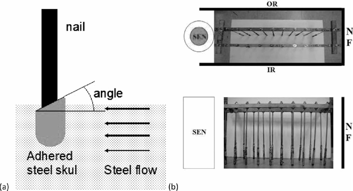
Nail-board method has been long used to get the direction of the flow at multiple location at a time as shown in the Fig. 11, however by measuring the diameter and height of steel deposition on the nail, a crude estimation of the prevailing velocity is also possible by a correlation.102)
Care must be taken about material of the nail like stainless steel in case of FC mold and timing & verticality of the dip.
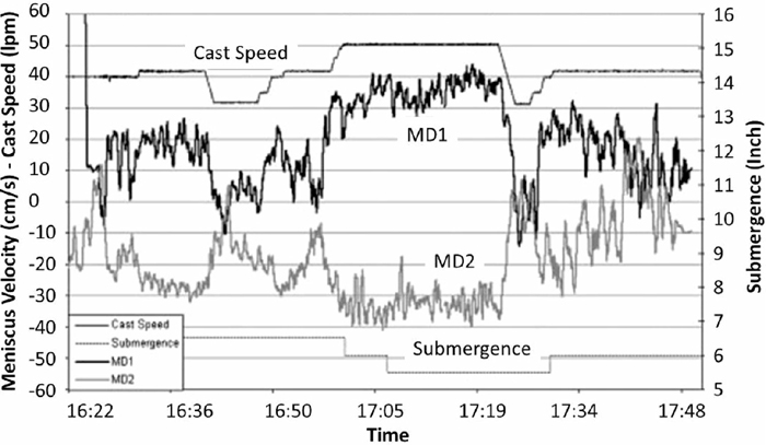
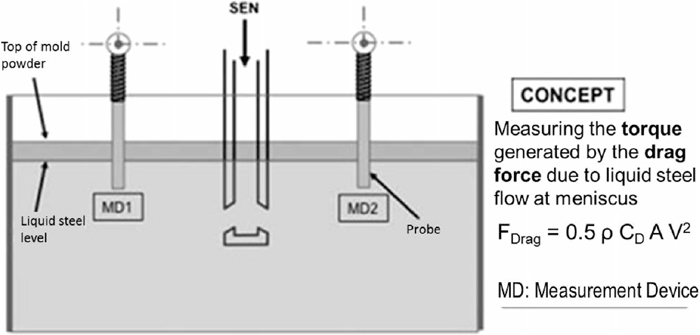
Sub-meniscus flow velocity measurement through torque technique uses the concept of correlating measured torque values to the flow velocity as shown in Fig. 9. Figure 10 depicts a typical transient velocity result for varying caster parameters like casting speed, submergence depth etc. The limitation of this technique is that it provides a single point measurement, which corresponds to an average velocity of the flow in the area of the submerged length. Care must be taken to recalibrate the velocity data based on the actual submergence of the probe as the slag/liquid steel flow may incur significant amount of wear on the probe.
Inclination angle method was used by Visser100) at IJmuiden. It uses a pivotal device as shown in Fig. 12 to measure the inclination angle of a ceramic tube immersed in the liquid steel unto certain depth. The force due to steel flow underneath meniscus causes the ceramic tube to deviate from vertical position thus average steel flow velocity can be correlated by the angle. The direction of the tube inclination also indicates the flow direction. From moment balance of gravity, buoyancy, and frictional forces:
|
Σ
i=steel,slag
(
m
i⋅
l
i
)
⋅
g
⋅
sin α=
Σ
x=steel,slag
(
V
x⋅
ρ
x⋅
l
x
)
⋅
g
⋅
sin α
+
0.5
⋅
C
D⋅
A
⊥,steel⋅
ρ
steel⋅
v
2
⋅
l
steel⋅
cos α
|
Where
m = mass of the different components of the ceramic tube
l = arm of that component or immersed part
α = angle of inclination of the tube from its vertical position
V = volume of the immersed part of the tube
ρ = density of the liquid
CD = drag coefficient
A⊥,steel = cross-sectional area of the immersed part of the tube and
v = steel flow velocity.
In the set-up immersion depth of the ceramic tube is an important parameter and must be chosen carefully to represent prevailing steel flow velocity.
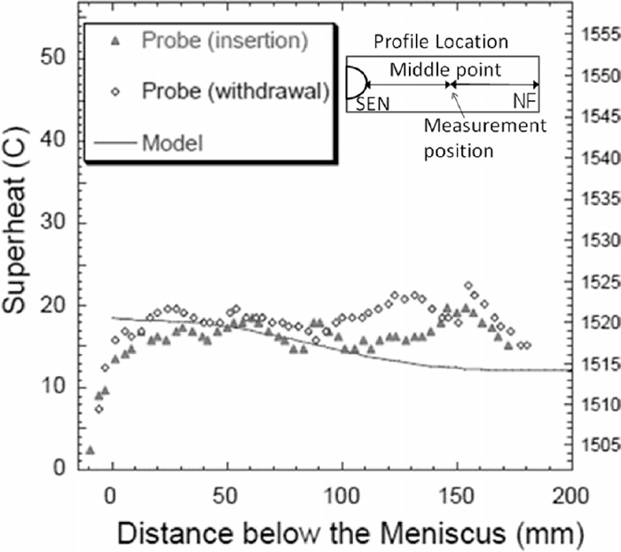
Inside the mold cavity, temperature of the molten steel can be measured by inserting thermocouple probe downward through the top surface at several locations in an operating caster as done by Thomas82) for the Mansfield caster. Care was taken to slowing insert the probe to allow for thermal equilibrium. A typical such measurement data is shown in Fig. 13.
6. Conclusion
The advances in the area of thermo-fluid modeling of a continuous slab caster is presented and discussed in a progressive manner mainly for the last decade. The challenges of solidification modeling and solutions proposed by various researchers have been outlined.
Complex and coupled multiphase, multi-physics, multi-scale, multi-component phenomena are required to be considered to have a complete model of a continuous caster along with suitable validation with the real caster data. Significant progress has been made to take into account detailed 3D transient thermal buoyant flow with anisometric turbulence under the influence of electromagnetism. Caster dynamics such as oscillations, overlying mold flux, argon bubbling, shell thinning, inclusions in presence of mushy region with appropriately varying thermo-physical properties is demonstrated with sufficient confidence. Development of careful measurement techniques to capture the data for model validation has added to accuracy and predictability.
Multi-scale modeling of a caster to realistically simulate the phenomena in the mushy region is still a future challenge. On the other hand, extending the concept of thermo-fluid modeling to include mechanical stress-strain history to enable auxiliary caster systems more efficient.
Thus, the work summarized in this paper can be helpful for further modeling investigation of the continuous casting mold, and to improve understanding of this important industrial process.
References
- 1) B. G. Thomas and L. Zhang: ISIJ Int., 41 (2001), 1181.
- 2) B. G. Thomas: Metall. Mater. Trans. B, 33 (2002), 795.
- 3) R. Singh, B. G. Thomas and S. P. Vanka: Metall. Mater. Trans. B, 45 (2014), 1098.
- 4) L. Zhang and Q. Wang: TMS Annu. Meeting. Suppl. Proc., TMS, Warrendale, PA, (2015).
- 5) G. Lesoult, H. Combeau and M. Moukassi.: J. Phys. IV, 3 (1993), 813.
- 6) D. Mazumdar and J. W. Evans: Model. Steelmaking Processes, CRC Press, Florida, (2010), 290.
- 7) S. Janaa, S. Rayb and F. Durst: Appl. Math. Model., 31 (2007), 93.
- 8) C. Andersson: PhD Thesis, Royal Institute of Technol., Stockholm, (2002), 3.
- 9) V. R. Voller: Int. J. Heat Mass Transf., 30 (1987), 1709.
- 10) V. R. Voller and A. D. Brent: Int. J. Heat Mass Transf., 32 (1989), 1719.
- 11) V. R. Voller, C. R. Swaminathan and B. G. Thomas: Int. J. Numer. Methods Eng., 30 (1990), 875.
- 12) J. Szekely and V. Stanek: Metall. Mater. Trans. B, 1 (1970), 119.
- 13) B. G. Thomas and F. M. Najjar: Appl. Math. Model., 15 (1991), 226.
- 14) H. Yang, L. Zhao, X. Zhang, K. Deng, W. Li, and Y. Gan: Metall. Mater. Trans. B, 29 (1998), 1345.
- 15) S. Qiu, H. Liu, S. Peng and Y. Gan: ISIJ Int., 44 (2004), 1376.
- 16) Q. Yuan, B. Zhao, P. Vanka and B. G. Thomas: Steel Res., 76 (2005), 33.
- 17) S. G. Hernandez, J. D. J. Barreto, R. D. Morales and H. A. Gutierrez: ISIJ Int., 53 (2013), 809.
- 18) B. G. Thomas, B. Ho and G. Li: Alex McLean Symp. Proc., ISS, Warrendale, PA, (1998), 177.
- 19) G. D. Lawson, S. C. Sander, W. H. Emling, A. Moitra and B. G. Thomas: Steelmaking Conf. Proc., Vol. 77, ISS, Warrendale, PA, (1994), 329.
- 20) X. Huang, B. G. Thomas and F. M. Najjar: Metall. Mater. Trans. B, 23B (1992), 339.
- 21) R. A. Parsons, K. A. Tieu and W. K. Soh: 20th Australian Fluid Mechanics Conf., The University of Sydney, Australia, (1995), 501.
- 22) M. Brummayer, P. Gittler and J. Watzinger: 2nd Int. Conf. on CFD in the Minerals and Process Ind., CSIRO, Australia, (1999), 217.
- 23) S. K. Das, K. M. Godiwalla and S. P. Mehrotra: Heat Mass Transf. Conf., IIT Guwahati, India, C297 (2006), 2146.
- 24) B. Zhao, B. G. Thomas, S. P. Vanka and R. J. O’Malley: Metall. Mater. Trans. B, 36 (2005), 802.
- 25) M. Wu, A. Vakhrushev, G. Nummer, C. Pfeiler, A. Kharicha and A. Ludwig: Open Transp. Phenom. J., 2 (2010), 16.
- 26) T. Cebeci: J. Heat Transf., 95 (1973), 227.
- 27) J. Blom: Proc. 4th Int. Heat Transf. Conf., Vol. 2, Eisevier, Amsterdam, (1970), 1970.
- 28) S. Yokoya, S. Takagi, M. Iguchi, K. Marukawa, W. Yasugaira and S. Hara: ISIJ Int., 40 (2000), 584.
- 29) Y. H. Ho, C. H. Chen and W. S. Hwang: Ironmaking Steelmaking, 28 (2001), 258.
- 30) A. R. Banderas, R. S. Pérez, R. D. Morales, J. P. Ramos, L. D. García and M. D. Cruz: Metall. Mater. Trans. B, 35 (2004), 449.
- 31) H. J. Odenthal, I. Lemanowicz, R. Gorissen and H. Pfeifer: Metall. Mater. Trans. B, 33 (2002), 163.
- 32) P. Mishra, S. K. Ajmani, A. Kumar and K. K. Srivastava: IJEST, 4 (2012), 2234.
- 33) L. Zhang, S. Yang, K. Cai, J. Li, X. Wan and B. G. Thomas: Metall. Mater. Trans. B, 38 (2007), 63.
- 34) Q. Yuan, S. Sivaramakrishnan, S. P. Vanka and B. G. Thomas: Metall. Mater. Trans. B, 35 (2004), 967.
- 35) V. Singh, S. K. Dash, J. S. Sunitha, S. K. Ajmani and A. K. Das: ISIJ Int., 46 (2006), 210.
- 36) I. C. N. Ramos and R. D. Morales: Metall. Mater. Trans. B, 46 (2015), 1314.
- 37) S. Qiu, H. Liu, S. Peng and Y. Gan: ISIJ Int., 44 (2004), 1376.
- 38) M. R. Aboutalebia, M. Hasana and R. I. L. Guthrie: Numer. Heat Transf. A, 28 (1995), 279.
- 39) P. E. R. Lopez, P. D. Lee, K. C. Mills and B. Santillana: ISIJ Int., 50 (2010), 1797.
- 40) P. E. R. Lopez, P. D. Lee and K. C. Mills: ISIJ Int., 50 (2010), 425.
- 41) P. E. R. López: PhD Thesis, Imperial College London, UK, (2010).
- 42) F. F. Tsukihashi and B. B. Li: ISIJ Int., 45 (2005), 30.
- 43) F. R. Perez, C. R. Ramirez, R. M. Tello, R. H. Santoyo, F. C. Torre and J. G. Trejo: Math. Probl. Eng., 2014 (2014), 1.
- 44) P. E. R. Lopez, P. N. Jalali, J. Bjorkvall, U. Sjöström and C. Nilsson: ISIJ Int., 54 (2014), 342.
- 45) P. E. R. Lopez: PhD Thesis, Imperial College London, UK, (2010).
- 46) J. Anagnostopoulos: Metall. Mater. Trans. B, 30 (1999), 1095.
- 47) J. L. Liow, M. Rudman and P. Liovic: ISIJ Int., 41 (2001), 225.
- 48) Y. S. Hwang, P. R. Cha, H. S. Nam, K. H. Moon and J. K. Yoon: ISIJ Int., 37 (1997), 659.
- 49) B. Li, T. Okane and T. Umeda: Metall. Mater. Trans. B, 31 (2000), 1491.
- 50) Y. Haiqi, W. Baofeng, L. Huiqin and L. Jianchao: J. Mater. Process. Technol., 202 (2008), 179.
- 51) M. R. Aboutalebi, R. I. L. Guthrie and S. H. Seyedein: Appl. Math. Model., 31 (2007), 1671.
- 52) S. M. Cho, S. H. Kim and B. G. Thomas: ISIJ Int., 54 (2014), 855.
- 53) D. T. Creech: MS Thesis, University of Illinois at Urbana-Champaign, USA, (1998).
- 54) A. Yousif: MS Thesis, McGill University, (2012).
- 55) J. Sengupta, B. G. Thomas, H. J. Shin, G. G. Lee and S. H. Kim: Metall. Mater. Trans. B, 37 (2006), 1597.
- 56) H. Bai and B. G. Thomas: Metall. Mater. Trans. B, 32 (2001), 253.
- 57) B. G. Thomas, X. Huang and R. C. Sussman: Metall. Mater. Trans. B, 25 (1994), 527.
- 58) P. H. Dauby, M. B. Assar and G. D. Lawson: Rev. Métall.-CIT, 98 (2001), 353.
- 59) M. M. Yavuz: Ironmaking Steelmaking, 38 (2011), 453.
- 60) M. D. Santis and A. Ferrettl: ISIJ Int., 36 (1996), 673.
- 61) B. Santillana, R. Boom, D. Eskin, H. Mizukami, M. Hanao and M. Kawamoto: Metall. Mater. Trans. B, 43 (2012), 5048.
- 62) R. Mehrabian, M. Keane and M. C. Flemings: Metall. Mater. Trans. B, 1 (1970), 1209.
- 63) T. Fujii, D. R. Poirier and M. C. Flemings: Metall. Mater. Trans. B, 10 (1979), 331.
- 64) M. Alizadeh, H. Edris and A. Shafyei: Int. J. Iron Steel Iron, 3 (2006), 7.
- 65) P. Sismanis: InTechOpen, 6 (2011), 121.
- 66) W. D. Bennon and F. P. Incropera: Int. J. Heat Mass Transf., 30 (1987), 2171.
- 67) N. Ramachandran, J. R. Gupta, Y. Jalunu and T. Bermat: Int. J. Heat Mass Transf., 25 (1982), 187.
- 68) D. K. Gartling: Computer Methods in Fluids, Pentech, London, (1980), 257.
- 69) J. P. Gu and C. Beckermann: Metall. Mater. Trans. A, 30 (1999), 1357.
- 70) S. H. Seyedein and M. Hasan: Int. J. Heat Mass Transf., 40 (1997), 4405.
- 71) H. Mehrara, B. Santillana, D. G. Eskin, R. Boom, L. Katgerman and G. Abbel: Mater. Sci. Eng., 27 (2011), 1.
- 72) H. Liu, C. Yang, H. Zhang, Q. Zhai and Y. Gan: ISIJ Int., 51 (2011), 392.
- 73) W. Ya-tao, Y. Zhen-guo, Z. Xiao-feng, W. Bao and L. Qing: 8th ECCC Cong., ASMET, Austria, (2014).
- 74) P. Galdiz, J. Palacios, J. L. Arana and B. G. Thomas: 8th ECCC Cong., ASMET, Austria, (2014).
- 75) Z. Liu, F. Qi, M. Jiang and B. Li: 8th ECCC Cong., ASMET, Austria, (2014).
- 76) M. H. Zarea, A. H. Meysami, S. Mahmoudi, M. Hajisafari and M. M. Atabaki: Orient. J. Chem., 29 (2013), 1325.
- 77) A. Miehe and U. Gross: 8th ECCC Cong., ASMET, Austria, (2014).
- 78) R. I. L. Guthrie and R. P. Tavares: Inter. Conf. on CFD in Mineral & Metal Processes and Power Generation, CSIRO, Australia, (1997).
- 79) J. Mahmoudi, M. Vynnycky, P. Sivesson and H. Fredriksson: Mater. Trans., 44 (2003), 1741.
- 80) B. G. Thomas: Modeling for Casting and Solidification Processing, Marcel Dekker, New York, (2001), 499.
- 81) Y. Meng and B. G. Thomas: Metall. Mater. Trans. B, 34 (2003), 685.
- 82) B. G. Thomas, R. O’Malley, T. Shi, Y. Meng, D. Creech and D. Stone: Proc. Conf. MCWASP IX, Aachen, Germany, (2000), 769.
- 83) M. Y. Ha, H. G. Lee and S. H. Seong: J. Mater. Process. Technol., 133 (2003), 322.
- 84) A. N. Bastida, R. D. Morales, S. G. Hernandez, E. T. Alonso and A. E. Zarate: ISIJ Int., 50 (2010), 830.
- 85) C. Pfeiler, B. G. Thomas, M. Wu, A. Ludwig and A. Kharicha: Steel Res., 77 (2006), 1.
- 86) M. Bellet and V. D. Fachinotti: Proc. MCWASP XI, 11th Int. Conf. on Model. of Casting, Welding and Advanced Solidification Processes, Opio, France, (2006), 169.
- 87) B. Tambunan: Proc. Semiloka Teknol. Simulasi dan Komputasi serta Aplikasi, Jakarta, Indonesia, (2006), 168.
- 88) M. R. R. I. Shamsi and S. K. Ajmani: ISIJ Int., 47 (2007), 433.
- 89) M. Hanao, M. Kawamoto and A. Yamanaka: ISIJ Int., 49 (2009), 365.
- 90) R. D. Morales and P. R. López: AISTech Proc., Vol. 1, Warrendale, PA, (2006), 1005.
- 91) X. Wang, L. Tanga, X. Zanga and M. Yao: J. Mater. Process. Technol., 212 (2012), 1811.
- 92) I. Unamuno, J. Ciriza, A. Gotti, M. R. Ridolfi, A. Chown and C. Tscheuschner: European Commission EUR 24176 EN Report, European Commission, EU, (2009).
- 93) P. E. R. Lopez, P. N. Jalali and C. Nilsson: 8th ECCC Proc. Cong., ASMET, Austria, (2014).
- 94) M. Wu, A. Ludwig, C. Pfeiler and F. Mayer: J. Iron Steel Res. Int., 15 (2008), 30.
- 95) Y. Belhamadia, A. S. Kane and A. Fortin: Int. J. Numer. Anal. Mod. B, 3 (2012), 192.
- 96) P. Du: PhD Thesis, University of Iowa, (2013).
- 97) A. Horr, R. Kretz and A. Petz: 8th ECCC Cong., ASMET, Austria, (2014).
- 98) S. A. Argyropoulos: Scand. J. Metall., 30 (2000), 273.
- 99) B. G. Thomas, Q. Yuan, S. Sivaramakrishnan, T. Shi, S. P. Vanka and M. B. Assar: ISIJ Int., 41 (2001), 1262.
- 100) H. H. Visser, W. V. Knoop, W. F. M. Damen, T. G. V. Essen, J. V. Oord, D. Bal, S. R. Higson and J. P. T. M. Brockhoff: Matell. Ital., 101 (2009), 61.
- 101) B. Rietow and B. G. Thomas: AISTech, Warrendale, PA, (2008), 1.
- 102) R. Liu, J. Sengupta, D. Crosbie, S. Chung, M. Trinh and B. G. Thomas: CCC Annual Report, UIUC, USA, (2010).
- 103) T. Wondrak, K. Klotsche, K. Timmel, F. Stefani, N. Shevchenko, S. Eckert and G. Gerbeth: 8th ECCC Cong., ASMET, Austria, (2014).
- 104) T. Wondrak, S. Eckert, G. Gerbeth, K. Klotsche, F. Stefani, K. Timmel, A. Peyton, N. Terzija and W. Yin: Metall. Mater. Trans. B, 42 (2011), 1201.
- 105) T. Wondrak, V. Galindo, G. Gerbeth, T. Gundrum, F. Stefani and K. Timmel: Meas. Sci. Technol., 21 (2010), 045402.
- 106) T. Wondrak, S. Eckert, V. Galindo, G. Gerbeth, F. Stefani, K. Timmel, A. Peyton and W. Yin: Ironmaking Steelmaking, 39 (2012), 1.
- 107) S. Markus, L. Torsten, M. Peter and R. Steffen: 8th ECCC Cong., ASMET, Austria, (2014).