Abstract
A new creep straightening casting curve that continuous casting slab can be straightened by full using of high-temperature creep property was proposed in this paper. The basic arc segment is cancelled in the new curve so that length of the straightening area can be extended and time of creep behavior can be increased significantly. In order to maximize the use of high-temperature creep property, various curvilinear equations with different changing rate of curvature were studied. The distance from solidifying front of slab at 1200°C is confirmed by finite element method. The strain rate at different locations which is beneath the center of inner arc surface were calculated when temperature is 1200°C. Uniaxial tensile tests of Q345C were carried out in order to obtain yield strength and minimum creep strain rate. It is concluded that the strain rate in the straightening area of new curve was less than minimum creep strain rate under yield strength at 1200°C. Therefore, strain rate can be below minimum creep strain rate on new creep straightening curve so that deformation of slabs depended on creep behavior only comes true. Continuous casting slab is straightened by means of creep strain so as to reduce the straightening strain and strain rate substantially. Internal cracks of slab caused by straightening could be effectively avoided, and the quality of the slab could be improved.
1. Introduction
Steel continuous casting is an important part in steel production and the continuous casting ratio has steadily increased, exceeding 90% in the 2000s.1) The presence of internal cracks in thick slabs is a critical defect during continuous casting, on account of these cracks will reduce product quality and affect the subsequent rolling process.2) Owing to the advancement of the understanding in steel solidification phenomena, steel structure, and strand behavior in the casting machine, caster profiles have been improved from simple vertical type to vertical and bending after complete solidification to curved mold and solid or liquid core unbending to vertical mold multi-point progressive bending and straightening with liquid core.1) It had been reported that the internal cracks are resulted from the excessive tensile strains produced by means of straightening at the solidifying front of the slab.3,4) Pascon et al. and Pascon and Habraken had done some research works on the risk of transverse cracking during bending and straightening of steel slabs.5,6) They indicated that Transverse cracks were most likely to occur at the edge on the upper face, at the end of straightening of the slab. This is due to the combination of low ductility of the material with tensile stress and elongation in the casting direction in the straightening zone. Li et al. had done researches about the formation of internal cracks in the bloom.7) They assumed that it is closely related to the deformation in the mushy zone, and When the equivalent plastic strain is larger than the critical strain and the equivalent von Mises stress exceeds the critical fracture stress during solidification, internal cracks will appear. Han et al. established a strain analysis model to study the effects of the strain status at solidifying front and the chemical composition of liquid steel on the internal cracks. The internal cracks were predicted by comparing the strain state at the solidifying front with experimental data based critical strains.8,9) Wang et al. had done analysis on the formation of internal cracks in continuous casting slabs. They concluded that the corresponding strain in the arc and horizontal segments does not exceed this critical value, so the solidification front in the straightening segments would be much easy to crack.10) These reaches indicated that it was necessary to reduce the strain and strain rate of the slab caused by bending and straightening at solid/liquid interface against internal cracks.
Usually it is said that creep behavior of steel is appreciable only at the temperature above forty percent of melting temperature.11) Hence the slab shows strong creep characteristics in present steel continuous casting production. Various researchers have investigated the effect of creep characteristics in the deformation processes of continuous casting slabs. In the earlier years, Grill and Schwerdtfeger developed an elastic and creep model for the prediction of bulging.12) The slab was considered as a bi-dimensional model because the restraining effect of the narrow face on the slab was neglected. Okamura and Kawashima presented a three-dimensional elastic-plastic and creep finite element model to predict the restraining effect of the narrow face on the bulging.13) On account of creep deformation, they concluded that the restraining effect could be neglected when the critical width to length ratio was above 3. In recent years, all kinds of modified model were proposed based on elastic-visco-plastic model. Bellet and Heinrich presented a global non steady-state approach to analyze global stress–strain of steel all along the continuous casting machine.14) They stated that elastic-visco-plastic models which included strain rate sensitivity at high temperature gave a better response than elastic-plastic models. Fachinotti and Cardona had done some research works on the great influence of the strain rate on the behavior of steel at elevated temperature. Different material models of steel at high temperature had been analyzed and compared. It could be found that rate-dependent visco-plastic models allowed this phenomenon that hardening had been observed in all their experimental results should be preferred. Koric and Thomas studied two thermo-mechanical models based on different elastic-visco-plastic constitutive laws are applied to simulate temperature and stress development of a slice through the solidifying shell of 0.27%C steel in a continuous casting mold under typical commercial operating conditions with realistic temperature dependant properties.15) Li and Thomas developed an elastic-visco-plastic creep constitutive equation to simulate temperature, stress, and shape development during the continuous casting of steel, both in and below the mold.16) It was concluded by them that inelastic strain included both strain-rate independent plasticity and time dependent creep. Creep was significant at the high temperatures of this process and was indistinguishable from plastic strain. These researches indicated that high temperature creep of the steel had significant influence on the deforming of the slab, which could not be overlooked in straightening and bending process. However, there is hardly any literature about deformation of continuous casting slab by full using of high-temperature creep behavior.
Based on the elastic-plastic theory, when a material is stressed within the elastic limit, a permanent deformation will not result. However, at the high temperatures the material is stressed less than yield strength will also result in a permanent deformation and there is only creep strain and no plastic strain in this deformation. Therefore, an attempt has been made here to illustrate the positive effects of high-temperature creep behavior on straightening technology of steel continuous casting. A new creep straightening curve which maximize the use of the high-temperature creep deformation during the slab straightening and bending process is proposed in this paper. Continuous casting slab is straightened by means of creep strain so as to reduce the straightening strain and strain rate substantially. Internal cracks can be avoided effectively and the productivity of the caster can be increased significantly.
2. Mathematical Model
Since the restraining effect of narrow face on the thick slab cannot be neglected, the neutral axis is assumed to be at the center of the slab. Therefore, the tensile strain at the solidifying front caused by bending and straightening can be calculated using Eq. (1).9,17,18)
|
ε
s
=(
D
2
-δ
)
(
k
i
-
k
i+1
)
| (1) |
Where D is slab thickness, δ is the solidified shell thickness, ki and ki+1 are the curvature of the starting point and the end point of straightening curve. The strain in some fibre at the distance from the solidifying front can be calculated using Eq. (2).
|
ε
h
=(
D
2
-δ+h
)
(
k
i
-
k
i+1
)
| (2) |
Where h is the distance from the solidifying front. As for continuous straightening curves, the curvature changes consecutively along the arc length. Thus, when the distance between any two adjacent straightening points tends to be infinitesimal, the strain at the point can be taken differentiate relative to arc length. The value of differentiate is the strain rate at the point relative to arc length. In the present work, Vc which stands for withdraw speed is considered as a constant at the steady casting state. Therefore, the strain rate in some distance from the solidifying front can be expressed as Eq. (3).
|
ε
˙
h
(t)=
lim
Δs→0
Δ
ε
h
Δs
Δs
Δt
=
V
c
lim
Δs→0
Δ
ε
h
Δs
=
V
c
(
D
2
-δ+h
)
k
′
(s)
| (3) |
Where k′(s) is the changing rate of curvature. From Eq. (3), it can be concluded that only the slab traverses through a path where there is a change of radius, the strain caused by straightening exists. There is no deformation in the basic arc segment of casting machine. The basic arc segment is cancelled so that length of the straightening area can be extended and time of creep behavior can be increased significantly. In addition, the curvature of straightening segment is changed so slowly that straightening strain rate can be reduced substantially. When the strain rate is reduced to be less than creep strain rate under yield strength at the same temperature, the slab can be straightened only by creep deformation.
3. Parameters of Creep Straightening Curve
As for continuous straightening, Li, Man and Li, Man et al. studied the high temperature character in continuous straightening process and proposed a late-model continuous straightening curve with two continuous straightening areas.19,20,21) In this paper, vertical-arc continuous casting that consists of vertical segment, bending segment, basic arc segment, straightening segment and horizon segment is considered. As for vertical-arc continuous casting curve, some key points need to pay more attention as follows:
(1) Bending segment curve is tangent to vertical line and straightening segment curve is tangent to horizon line. Due to cancel the basic segment, the slope of bending segment curve is equal to the straightening segment curve at the intersection.
(2) Different curves that curvature of bending segment curve is changed rapidly than straightening segment are designed. Because creep strain rate is faster at the higher temperature.
(3) Making the curvature of straightening segment changes as slow as possible so that the strain rate can be reduced less than creep strain rate under yield strength at the same temperature.
3.1. Bending Segment Curve Function
A function that the changing rate of curvature varies sinusoidally with arc length is presented for bending segment in this work. The changing rate of curvature in the bending segment can be express by Eq. (4).
|
k
1
′
(s)=
dk(s)
ds
=
A
1
sin(
B
1
s)
| (4) |
Where
k
1
′
(s)
is the changing rate of curvature in bending segment, s is the arc length, A1 and B1 are undetermined coefficients. Taken the integral for arc length, Eq. (4) transforms into
|
k
1
(s)=
dα(s)
ds
=2
A
1
B
1
sin
2
(
B
1
2
s
)
-1+
C
1
| (5) |
Where α(s) is the angle of rotation in the curve relative to arc length, C1 is the integration constant. A1, B1 and C1 can be calculated by means of following boudary conditions so as to connect vertical segment and straightening segment smoothly.
|
{
k(0)=0
k
′
(0)=0
k
″
(0)=0
k(
L
1
)=1/R
| (6) |
Where L1 is the arc length of the bending segment, R is the curvature radius at the intersection between bending and straightening segments. Substitute Eq. (6) into Eq. (5)
|
C
1
=1,
A
1
=
π
2R
L
1
,
B
1
=
π
L
1
| (7) |
The function of the bending segment curve can be expressed by Eq. (8).
|
k
1
(s)=
dα(s)
ds
=
1
R
sin
2
(
πs
2
L
1
)
| (8) |
A quintic polynomial without even numbers in exponents curvature function relative to arc length is proposed for straightening segment.
|
k
2
(s)=
A
2
s
5
+
B
2
s
3
+
C
2
s
| (9) |
Where k2(s) is the curvature of straightening segment, s is the arc length, A2, B2 and C2 are undetermined coefficients. In order to connect horizontal segment and bending segment smoothly, the same as boundary condition of bending segment is applied to the straightening segment. The beginning point of the curve is at the intersection between straightening and horizontal segments. Equation (10) is constructed to satisfy this boundary condition.
|
k
2
(s)=
1
R
(
1
2
+μ(
s-
L
2
2
)
)
| (10) |
Where L2 is the arc length of the straightening segment, μ(s−L2/2) is a quintic polynomial function without even numbers in exponents as Eq. (11).
|
μ(x)=a
x
5
+b
x
3
+cx
| (11) |
Where a, b and c are undetermined coefficients, x is used to stand for (s−L2/2).
|
{
s=0,
k
2
(s)=0,μ(
-
L
2
2
)
=-
1
2
s=
L
2
,
k
2
(s)=
1
R
,μ(
L
2
2
)
=
1
2
s=0,
k
2
′
(s)=0,
μ
′
(
-
L
2
2
)
=0
| (12) |
According to Eq. (12), a can stand for b and c like Eq. (13).
|
{
b=-
a
L
2
5
+4
2
L
2
3
c=
a
L
2
7
+24
L
2
2
16
L
2
3
| (13) |
Substituting Eq. (13) into Eq. (11) and taken the derivative of Eq. (11).
|
μ
′
(x)=5a
x
4
-
3(a
L
5
+4)
2
L
3
x
2
+
a
L
7
+24
L
2
16
L
3
| (14) |
|
μ
″
(x)=20a
x
3
-
3(a
L
5
+4)
L
3
x
| (15) |
Eventrually, a can be calculated by the method of the extremum of function. The coefficients b and c are solved from Eq. (13).
|
a=-
6
L
5
,b=
1
L
3
,c=
9
8L
| (16) |
Substituting Eqs. (16) and (11) into Eq. (10) and the function of the straightening segment curve can be presented by Eq. (17).
|
k
2
(s)=
1
R
(
1
2
-
6
L
2
5
(
s-
L
2
2
)
5
+
1
L
2
3
(
s-
L
2
2
)
3
+
9
8
L
2
(
s-
L
2
2
)
)
| (17) |
It is noteworthy that the curvature functions of bending and straightening segments are proposed in different coordinate systems. One of independent coordinate systems must be transited and rotated before curves of bending and straightening segments are connected smoothly. Make sure that the slope of bending segment curve is equal to the straightening segment curve at the intersection in the same coordinate systems. Since the slope can be calculated by curvature radius and arc length, the curve of continuous casting machine is only determined finally by the parameters of R and L1 or L2 in Eqs. (8) and (17).
4. Example of Creep Straightening Curve
In this paper, the R9300 vertical-arc slab casting machine of one steel mill is considered. Five-point bending and five-point straightening following the straight section are used. There is a long basic arc segment between bending and straightening segments. Its main paremeters are shown in Table 1.
Table 1. Parameters of R9300 and creep straightening casting curves.
| Parameters of curves | R9300 casting curve | Creep straingtening curve |
|---|
| Basic arc length [mm] | 13300 | 0 |
| Vertical segment [mm] | 1465 | 1000 |
| Bending segment [mm] | 1030 | 8000 |
| Straightening segment [mm] | 1520 | 12274 |
| Height of casting machine [mm] | 12305.55 | 11991.7 |
| Metallurgical length [mm] | 35862 | 35862 |
| Curvature radius of bending segment [mm] | ∞ | ∞ |
| 49420.834 | 9000 |
| 24328.140 |
| 15971.287 |
| 11797.719 |
| Curvature radius at intersection [mm] | 9300 |
| Curvature radius of straightening segment [mm] | 11312.892 |
| 14671.987 |
| 21396.378 |
| 41581.549 |
| ∞ | ∞ |
Generally speaking, basic arc radius of casting machine is determined by empirical Eq. (18).
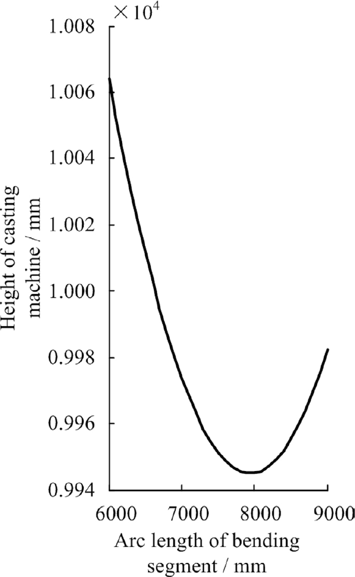
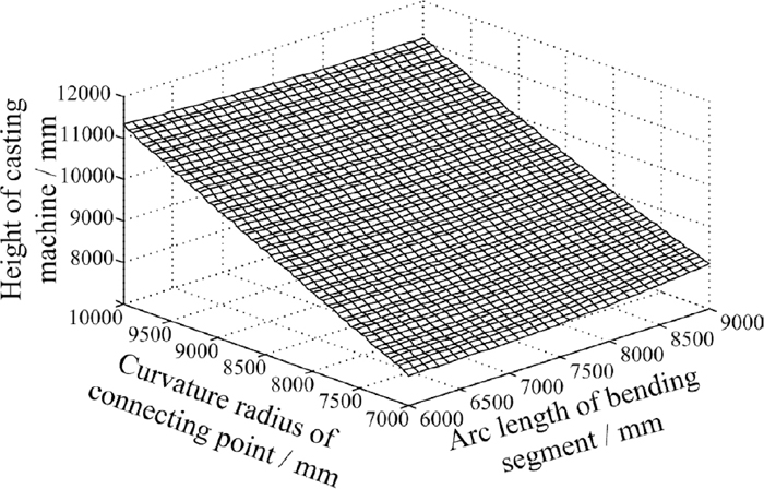
Where D is slab maximum thickness, ε0 is critical strain on the upper face of slab with the range from 1.5% to 2%. When the slab thickness is 230 mm, critical strain is 1.5%, radius of slab casting machine should be above 7666 mm. As for creep straightening casting curve, basic arc segment was cancelled so that the curvature radius of connecting point between bending and straightening segment must be above 7666 mm.The height of casting machine would rise up with increasing the curvature radius of connecting point and the strain rate would improve with decreasing the curvature radius of connecting point. Based on parameters of R9300 casting machine, curvature radius of connecting point between bending and straightening segment should be 9000 mm so as to minimize the change of origin R9300 casting machine. Relationship of multi-parameters on continuous casting machine of new creep straightening casting curve are shown from Fig. 1.
It can be concluded that the arc length of bending segment is close to 8000 mm and the height of the creep straightening casting machine could be minimum, when the curvature radius of connecting point is 9000 mm from Fig. 2.
The slope of tangent line in one point of curve can be calculated by Eq. (19).
|
K=tanα(s)=tan∫
k(s)ds
| (19) |
Where K is the slop, α is the angle of rotation in the curve relative to arc length, k is the curvature. Taken the integral for arc length to Eq. (8). The slopes of bending and straightening segment can be expressed by Eq. (20).
|
K
1
=tan
α
1
(
L
1
)=
L
1
R
K
2
=tan
α
2
(
L
2
)=
L
2
2R
| (20) |
The slope can be calculated to be 0.0155 in the X′O′Y′ coordinate system at the end of bending segment by Eq. (20), when arc length of bending segment is 8000 mm and the curvature radius of connecting point is 9000 mm. In order to connect bending and straightening segment smoothly, the relationship of α1 and α2 can be expressed as follow in the same coordinate system.
Thus, in the same XOY coordinate system, the slop at the intersection between bending and straightening curves is shown by Eq. (22).
|
tan
α
2
=tan(
π
2
-
α
1
)
=tan(
π
2
-
8 000
9 000
)
=0.119
| (22) |
The arc length of straightening segment is 12274 mm so as that the slope of bending segment curve is equal to the straightening segment curve at the intersection in the same coordinate systems. Equations of bending and straightening segments can be expressed with the determination of L1, L2 and R.
Bending segment,
|
k
1
(s)=
1
9 000
sin
2
(
πs
16 000
)
(0≤s≤8 000)
| (23) |
Straightening segment,
|
k
2
(s)=
1
9 000
(
-2.154×
10
-20
(s-6 137)
5
+5.408×
10
-13
(s-6 137)
3
+9.166×
10
-5
(s-6 137)+0.5
)
(0≤s≤12 274)
| (24) |
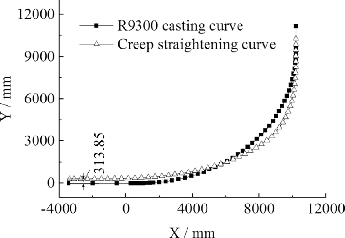
Curves of vertical, bending, straightening and horizontal segments are connected smoothly and the eventural creep straightening curve is shown by Fig. 3. Parameters of new creep straightening casting are shown in Table 1 too. With the top of mold as a common starting point, curves of R9300 casting machine and creep straighteing casting machine are drawn in the same coordinate system by auto-cad software in Fig. 4, according to the parameters of two curves in Table 1. It is clear that the height of new creep straightening casting curve is 313.85 mm lower than the R9300 casting machine From Fig. 4.
It is neccessary to confirm the location of the solidifying front so as to calculate the strain rate accurately at the distance from solidifying front. A bi-dimensional finite element model with half of transversal section in the slab is developed as shown in Fig. 5 by the method of inhomogeneous meshing.
The secondary cooling schedule listed in Table 2 same as R9300 casting machine is applied to this model. The coefficient of heat transfer between water and surface of slab can be calculated by empirical Eq. (25) based on the Table 2.
|
H=0.58
W
0.451
(
1-0.0075
T
W
)
| (25) |
Table 2. Secondary cooling schedule of creep straightening casting machine.
| Zone NO. | Zone of roller number | Loop NO. | Location | Water flow rate [m3/h] | AIRE [m3/h] |
|---|
| 1 | Foot roller | 1 | Wide surface in and out | 9.0 | 9000 |
| 2 | Narrow surface left and right | 1.2 |
| 2 | 1#–6# | 3 | Wide surface in and out | 65.0 |
| 4 | Narrow surface left and right | 7.0 |
| 3 | 7#–13# | 5 | Wide surface in | 30.0 |
| 6 | Wide surface out | 30.0 |
| 4 | 14#–18# | 7 | Wide surface in | 13.0 |
| 8 | Wide surface out | 17.0 |
| 5 | 19#–23# | 9 | Wide surface in | 14.0 |
| 10 | Wide surface out | 18.0 |
| 6 | 29#–34# | 11 | Wide surface in | 9.3 |
| 12 | Wide surface out | 13.5 |
| 7 | 39#–44# | 13 | Wide surface in | 12.0 |
| 14 | Wide surface out | 18.0 |
| 8 | 54#–63# | 15 | Wide surface in | 9.0 |
| 16 | Wide surface out | 17.5 |
Where H is the coefficient of heat transfer, TW is the temperature of water flow, W is the density of water flow rate. Central segregation and heat transfer along the slab moving are neglected in this paper. Q345c steel is considered in present work. The chemical composition of this steel is given in Table 3. The shell thickness is given in Fig. 6 with the casting condition listed in Table 4.
Table 3. Chemical composition of Q345c.
| Steel | C [%] | Si [%] | Mn [%] | P [%] | S [%] | V [%] | Ti [%] |
|---|
| Q345c | 0.2 | 0.50 | 1.65 | 0.030 | 0.035 | 0.18 | 0.11 |
Table 4. Casting conditions.
| Parameter | Value |
|---|
| Steel casting speed [m min−1] | 1.5 |
| Working mold length [mm] | 900 |
| Initial temperature [°C] | 1545 |
| Liquidus temperature [°C] | 1520 |
| Solidus temperature [°C] | 1495 |
| Density [kg m−3] | 7200 |
| Poisson’s ratio | 0.3 |
It is easy to obtain the distance from solidifying front at any temperature using the same method. In general, the temperature of surface on slabs can be above 1000°C, when slabs are straightened. Cracks caused by straightening may occur at one location inner the slab. Thus, the location at 1200°C inner the slab is considered in this paper. It is clear that h1200 standing for the distance from solidifying front at 1200°C in one location of straightening segment is shown from Table 5. Table 5 shows the strain rate and changing rate of curvature from solidifying front and strain rate at 1200°C in some locations of straightening segment. Strain rate located in the slab of straightening segment at 1200°C is calculated by Eq. (3). The straightening segment composed by involute and qubic continuous straightening curves was practical applied to No.2 steelmaking plant in Ansteel group coporation by Man and Jing, also based on R9300 vertical-arc slab casting machine with five bending and five straightening.20,22) The maximum strain rate at solid-liquid interface were 7.55×10⁻⁵ s−1 in volute zone and 3.14×10⁻⁵ s−1 in qubic zone when the withdraw speed was 1.6 m/min. Because of the decline of strain rate, the ratio of abnormal sulphur print after modification during August to October in 2006 decrease by 16.67%, 43.87%, 36.95% than 2005. However, the maximum strain rate at solid-liquid interface of creep straightening curve calculated by Eq. (3) is 1.07×10⁻⁵ s−1. It can be concluded that due to the more lower strain rate, internal cracks caused by straightening could be effectively avoided, and it is important to improve the quality of the slab.
Table 5. Relationship of various parameters with arc length of straightening segment at 1200°C.
| Arc length of straightening sgement [mm] | 1000 | 2000 | 3000 | 4000 | 5000 | 6000 | 7000 | 8000 | 9000 | 10000 | 11000 | 12000 |
|---|
| h1200 [mm] | 86.95 | 85.40 | 83.98 | 82.82 | 81.63 | 80.35 | 79.02 | 77.68 | 76.28 | 74.89 | 73.50 | 72.10 |
| Curvature [10−5 mm−1] | 10.75 | 9.90 | 8.86 | 7.78 | 6.72 | 5.70 | 4.67 | 3.62 | 2.54 | 1.48 | 0.56 | 0.03 |
| Strain Rate [10−5 s−1] | 1.44 | 2.08 | 2.27 | 2.23 | 2.12 | 2.05 | 2.04 | 2.07 | 2.07 | 1.91 | 1.43 | 0.40 |
5. Experiment of Creep Strain Rate
Uniaxial tensile tests of Q345c by constant strain rate and constant load are carried out separatedly on Gleeble-3800 machine. In order to simulate continuous casting, the heating rate was 10°C s−1 to 1320°C and holding the temperature for 2 minutes. Controlled cooling rate to the tensile test temperature was 3°C s−1 and holding time the temperature before tensile testing is 3 minutes.23,24) The specimens in10 mm diameter by 120 mm long threaded at both ends as shown Fig. 7 were submitted to 0.01 s−1 constant strain rate tensile tests at temperatures of 1200°C in Gleeble-3800 machine. According to the true stress-strain experimental data, numerical data of 0.2 offset yield strength of Q345c steel at temperatures of 1200°C are given in Fig. 8.

The schematic thermal cycle the same as the heating ductility is used to carry out the creep tensile test. Constant load tensile tests under 1100 N corresponding to stress about 14 MPa less than yield strength 16.12 MPa at 1200°C are carried out by using of the same specimens in Gleeble-3800 machine. According to the casting speed and metallurgical length in the R9300 casting machine, time of creep tensile test is considered as 1200 second. Figure 9 shows creep strain curve consisted of three stages, and that primary, secondary and tertiary. Firstly there is a relatively short initial period in which the creep strain increases at variable rate. And then there is long period with the creep strain increasing at constant rate. Lastly creep strain increases rapidly and fracture occurs. It can be seen that the minimum creep strain rate under 14 MPa is 7.45×10⁻⁵ s−1 from Fig. 9.

The yield strength is 16.12 MPa and the minimum creep strain rate under 14 MPa is 7.45×10⁻⁵ s−1, when the temperature is 1200°C. It can be concluded that the strain rate in slab of straightening area is less than creep strain rate under yield strength at 1200°C in the new creep straightening curve from Fig. 10. There are only creep deformation in these locations of slab, when the temperature is 1200°C. Thus, some areas in the slab can be straightened only by high-temperature creep behavior.
6. Conclusion
A new creep straightening casting curve full using of high-temperature creep behavior is proposed in this paper. The basic arc segment is cancelled in the new curve so that length of the straightening area can be extended and time of creep behavior can be increased significantly based on the R9300 vertical-arc continuous casting machine. The curvature of bending segment curve is changed rapidly than straightening segment in the creep straightening curve. In addition, the height of new creep straightening casting curve is 313.85 mm lower than the R9300 casting machine.
The distance from solidifying front in the slab at 1200°C is calculated by finite element method. Strain rate located in the slab of straightening segment at 1200°C is confirmed and creep strain rate less than yield strength at 1200°C is obtained by means of uniaxial tensile tests of Q345c. It can be concluded that the strain rate in slab of straightening area is less than creep strain rate under yield strength at 1200°C in the new creep straightening curve. The new creep straightening technology can make strain rate below creep strain rate so that deformation of slabs depended on creep behavior only comes true. Continuous casting slab was straightened by means of creep strain so as to reduce the straightening strain and strain rate substantially. Internal cracks caused by straightening could be effectively avoided, and it is important to improve the quality of the slab. It is helpful for the design of the new casting machine and improvement of old casting machine depended on high temperature creep property.
Acknowledgements
This research was financially supported by the National Science Foundation of China under the Grant No. 51275446, the Hebei Provincial Natural Science Foundation of China under the Project No. E2016203492 and the Hebei Provincial project for Returned overseas personnel No. C2013005012. The authors thank the National Science Foundation of China and Hebei Provincial Natural Science Foundation of China for funding of this research work.
References
- 1) H. Tomono: Ironmaking Steelmaking, 42 (2015), 242.
- 2) F. M. Du, X. D. Wang and Y. Liu: ISIJ Int., 55 (2015), 2150.
- 3) K. Kim, H. N. Han, T. Yeo, Y. Lee, K. H. Oh and D. N. Lee: Ironmaking Steelmaking, 24 (1997), 249.
- 4) A. Yamanaka, K. Nakajima and K. Okamura: Ironmaking Steelmaking, 22 (1995), 508.
- 5) F. Pascon, S. Cescotto and A. M. Habraken: Int. J. Numer. Methods Eng., 68 (2006), 125.
- 6) F. Pascon and A. M. Habraken: Comput. Methods Appl. Mech. Eng., 196 (2007), 2285.
- 7) X. B. Li, H. Ding, Z. Y. Tang and J. C. He: Int. J. Miner. Metall. Mater., 19 (2012), 21.
- 8) Z. Q. Han, W. X. Yuan and K. K. Cai: J. Univ. Sci. Technol. Beijing, 6 (1999), 268.
- 9) Z. Q. Han, K. K. Cai and B. C. Liu: ISIJ Int., 41 (2001), 1473.
- 10) B. Wang, J. M. Zhang, C. Xiao, S. X. Wang and W. Song: High Temp. Mat. Pr-Isr., 35 (2016), 269.
- 11) V. Raghavan: Materials Science and Engineering, Prentice-Hall of India, New Delhi, (2004).
- 12) A. Grill and K. Schwerdtfeger: Ironmaking Steelmaking, 6 (1979), 131.
- 13) K. Okamura and H. Kawashima: ISIJ Int., 29 (1989), 666.
- 14) M. Bellet and A. Heinrich: ISIJ Int., 44 (2004), 1686.
- 15) S. Koric and B. G. Thomas: J. Mater. Process. Technol., 197 (2008), 408.
- 16) C. Li and B. G. Thomas: Metall. Mater. Trans. B, 35 (2004), 1151.
- 17) Y. P. Sheng, J. Q. Sun and M. Zhang: Iron Steel, 28 (1993), 20.
- 18) R. K. Verma and N. U. Girase: Ironmaking Steelmaking, 33 (2006), 471.
- 19) X. K. Li: Iron Steel, 31 (1996), 31.
- 20) Y. Man and X. K. Li: J. Plast. Eng., 15 (2008), 96.
- 21) Y. Man, X. K. Li and L. D. Yang: Mater. Sci. Forum, 30 (2008), 7.
- 22) F. R. Jing, X. K. Li, L. D. Yang, H. G. Sun, T. G. Wang and Z. Y. Chen: Iron Steel, 44 (2009), 23.
- 23) Z. H. Dong: Chin. J. Mater. Res., 27 (2013), 273.
- 24) X. D. Kang, H. S. Dong and X. M. Zhang: J. Northeast. Univ., 25 (2004), 40.