Regular Article
Comparison of Thermo-electromagneto-hydrodynamic Multi-physical Fields in ESR Furnace with Vibrating and Traditional Electrodes
2017 年 57 巻 1 号 p. 91-99
詳細
2017 年 57 巻 1 号 p. 91-99
The transient three-dimensional (3D) full-coupled multi-physical fields in the Electroslag-Remelting (ESR) process with the vibrating and traditional electrodes have been compared in this paper. A mathematical model for simultaneously predicting the electromagnetic phenomenon, heat transfer, two phase flow and solidification has been established in the ESR furnace. Especially, the Joule heating and electromagnetic force are calculated by self-developed program based on the magnetohydrodynamic (MHD) model. The effects of the vibrating modes, such as horizontal and vertical vibration, on the heat transfer and MHD two-phase flow as well as solidification are clarified. The results indicate that the melting rating can be increased in the ESR process with vibrating electrode. The small-scale factory experiments are conducted and a reasonable agreement between the experimental observations and numerical results is obtained. The variation of temperature distribution dominated by the dropping behavior of the metal droplets is ordered and periodic. Particularly, the distinct variation of temperature distribution occurs beneath the bottom tip of the electrode. The horizontal vibrating ESR process can generate smaller metal droplets, which provide less energy (heat plus momentum) into the metal pool, constitute a shallower pool and a lower average temperature gradient. Moreover, with the increasing amplitude or frequency, the average temperature gradients for both cases decrease.
The electroslag remelting (ESR) process is one of the most distinguished methods for the secondary refining of special steel, such as die steel, ball bearing steel or nuclear power steel.1) Figure 1 represents a schematic drawing of the ESR process. In general, the original current flow from a self-consumable electrode continuously inserted into the molten slag layer, through molten metal pool, to a directional solidification ingot. The massive Joule heating heat the slag layer, leading to the melting of bottom tip of electrode.2) In the meanwhile, when the tip melts, the molten droplets form and pass through the slag layer pool into the molten metal pool. This process offers a possibility for the inclusion removal and chemical refinement of molten droplets.3)
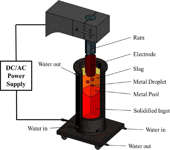
Schematic diagram of electroslag remelting process. (Online version in color.)
The initial comments of optimizing operational parameters and refining chemical composition have been suggested to produce high quality ingots with ESR technique. Nevertheless, few have significant effects.4,5,6) The efficiently relative movement between the electrode and molten slag, resulting in homogenizing organization and increasing melting rate, has been demonstrated and verified in the past few years.7) Based on it, the innovative vibrating electrode method has been proposed.8) Instead of the motionless electrode, it would vibrate periodically in a vertical or horizontal direction during the ESR process. Therefore, the vibrating of electrode will change the formation mechanism of metal droplets. Meanwhile, the melting rate in the ESR system of vibrating electrode will be increased compared with the traditional electrode. In addition, it can be practicably implemented and applied in industrial application, which is beneficial to boost the rapid development of heavy industry and mechanical manufacture.
In order to put the ESR process of vibrating electrode into practice, an in-depth investigation should be considered. Physical experiments are not enough for evaluating the relationship between the operating parameters and process characteristics, since the physical phenomena are even intricate and the cost of materials and energy are too high. Moreover, it is too difficult to measure precisely and errorless in a high temperature environment. However, numerical simulation could provide a systematic and efficient way for exploring a basic understanding of the primary physical processes. Nowadays, many researches have studied the mathematical simulation of heat transfer and fluid flow in the ESR furnaces with traditional electrode.9,10,11) Jardy12,13) carried out a transient mathematical model by means of a mesh-splitting method to calculate the continuous growth of the ESR ingots. Vishwanathan and Melgaard14) developed and analyzed the effect of the important operating parameters on hear transfer, two-phase fluid flow, and solidification. Szekeley15,16) figured out a significant work in simulating the ESR process to solve the problem of heat transfer and fluid flow in the slag layer, molten pool and ingot. The work utilizes the standard turbulent model to resolve turbulent viscosity and turbulent thermal conductivity in the slag, and calculates the Maxwell equations to simulate the distribution of Lorenz force and the Joule heating in the slag. What’s more, the electromagnetic phenomenon, fluid flow and solidification in the ESR process with a novel electrode (rotating electrode) has been studied by Wang,17) in which the effect of a rotating electrode on the coupled physical fields are illustrated. Additionally, a three-dimension finite-element method considering the effect of two connected electrodes on the Joule heating and temperature distribution in the ESR system was clarified by Li.18) It successfully reveals the characteristics of the electromagnetic and temperature fields with two connected electrodes.
The purpose of the present study is to understand the mechanism of vibrating electrode on multi-physical fields in ESR process by a transient 3D comprehensive model, to compare the thermo-electromagneto-hydrodynamic phenomenon in the ESR furnaces with the vibrating and traditional electrodes. The physical experiments of the ESR furnace with the vibrating and traditional electrode are conducted to validate the reliability of the models. Meanwhile, the effect of the vibrating electrode modes (no vibration, horizontal vibration and vertical vibration) on the heat transfer and MHD two-phase flow are also represented in detail.
In the present work, a calculation model for the ESR system has been studied as a hypothesis of the real entity including the slag, metal pool, and ingot. The effect of temperature on densities of the slag and the metal is employed, and the electrical conductivity of the slag is considered to be dependent on the temperature, as shown in Table 1.19) The other physical parameters of slag and metal are set to be independent and constant.20) The tip configuration and immersion depth of the electrode will be remained unaltered. In order to approximating the real condition, the tip configuration of electrode applied in the calculation is flat, obtained by the laboratory observation.
| Properties | Metal | Slag |
|---|---|---|
| Density (kg·m−3) | ρmetal = 7820−0.8123 (T+273) | |
| Viscosity (kg·m−1·s−1) | 0.006 | 0.3 |
| Specific heat (J·kg−1·K−1) | 866 | 1255 |
| Thermal conductivity (W·m−1·K−1) | 35 | 10.46 |
| Volumic thermal expansion coefficient of the liquid (K−1) | 1×10⁻³ | 1×10⁻⁴ |
| Electrical conductivity (Ω−1·m−1) | 7.14×10⁵ | lnσ=−6769.0/T+8.818 |
| Latent heat of solidification (J·kg−1) | 2.77×10⁵ | \ |
| Liquidus temperature (K) | 1784 | 1650 |
| Solidus temperature (K) | 1716 | \ |
The basic electromagnetic governing equations are employed here. Since the displacement of electric current is much smaller than the electric conduction while the frequency is less than 50 Hz, the Maxwell equations can be expressed as follows:
Ampere’s law is
| (1) |
Ohm’s law:
| (2) |
Lorentz’s law:
| (3) |
In order to solve the above referenced governing equations, the governing equations of electrical potential originated from the conservation of the current, which is comprised of the electrical potential φ and the magnetic potential vector A, have been introduced as follows:
| (4) |
In the meanwhile, the magnetic fields could be expressed as a function of magnetic potential vector Ref:22)
The continuous equation and time-averaged Navier-Stokes equation are used to calculate the fluid fields of slag and molten metal:
| (5) |
Where the source term
Jardy12,13) has pointed out that the turbulent flow of the slag and liquid metal are weak in ESR process. The Reynolds-Averaged Navier-Stokes equations have been adopted to simulate the fluid flow, built on disintegrating the local velocity into a mean and a fluctuating value. We choose the RNG k−ε turbulence model, which is developed with a lower Reynolds number, especially for an enhanced wall function of the near-wall zone. The geometric reconstruction volume of fluid (VOF) model is employed to trace the metal/slag interface since it is a vigorous and wide applied technique.23,24) In addition, in order to make the electrode vibrate, the user-defined function (UDF) and dynamic mesh model have been used together.
2.3. Heat Transfer and SolidificationThe energy conservation equation based on the enthalpy theory is used to model the heat transfer and solidification phenomena of slag and molten metal in the ESR system:25)
| (6) |
| (7) |
Where, href and Tref are the reference enthalpy and the reference temperature, respectively, here href = 0 and Tref = 298 K. We consider fl, which represents a linear relation between temperature and liquid fraction, as
| (8) |
Where Am represents the mushy zone, here Am = 105. In the meanwhile, the slag layer is rising slowly while the metal pool is filled by the dropping metal droplets. Because of the small casting velocity (the order of 10−3 m/s), it could be ignored in Eq. (8).26) Source terms have also been added to the RNG k−ε turbulent equation in the mushy and solidified zones, separately:
Joule heating as a source term appears in the turbulent equations, where the thermal conductivity can be obtained from the turbulent viscosity.
A zero potential is imposed on the bottom tip of electrode while a potential gradient is enforced on the bottom surface of ingot. Considering the skin effect, a radial distribution of the current density is provided as follows:27,28)
| (9) |
The vibrating velocity will be imposed on the bottom tip of electrode. The direction of electrode vibrating is horizontal or vertical. The amplitude and frequency of electrode vibrating are shown in Table 1. The enhanced wall function could be introduced due to the low Prandtl number.29) Additionally, non- slip condition is set on the wall. At the top surface of slag, a zero shear stress is given. The initial conditions of volume fractions are metal = 1, slag = 0 in the molten pool zone and ingot zone and metal = 0, slag = 1 in the slag layer zone, respectively.
Considering the effect of varying melting rates on the Joule heating, the iterative procedure has been carried out as:
| (10) |
Where Qtotal, η, L and V represent the total value of Joule heating, the power efficiency, latent heat of slag and volume of slag layer, respectively. The value of power efficiency is too hard to carry out, due to the complex operating parameter. A reliable power efficiency is achieved from literature.30) Nevertheless, it has to be modified built on the actual condition of our experiment. A value of 0.18 has been adopted in the work. In addition, we have ignored the effect of slag skin thickness on the melt rate in this paper.
3.3. Heat Transfer and SolidificationThe heat exchange at the top surface of slag and the bottom of electrode tip are in the form of natural convection and thermal radiation. The inlet temperature of the molten metal is set as a parabolic profile, which has an estimated 30 K superheat compared with the metal liquidus, leading to a simple way of solving the melting process. The effective heat transfer coefficient is not an independent value, but depending on many factors. Hence, a tantamount heat transfer coefficient of slag-mold interface and metal-mold interface could be concluded from experiments and literatures.
The commercial software FLUENT, which is based on the finite volume method to discretize the governing equations, was developed to model the multi-physical fields. The MHD module of FLUENT was employed to simulate the electromagnetic field using self-developed program. A synchronous iterative solution process was used to calculate all the governing equations for electromagnetic field, temperature field, two-phase flow field and solidification. The effect of the phase change on the resultant electromagnetic force and Joule heating, which would be added into the source term of momentum and energy conservation equations, respectively, would be considered at each iteration. The combination of dynamic mesh model and the user-defined function (UDF) was introduced to process the motion of vibrating electrode. The iterative process would go on until all the normalized residuals were less than 10−6. In the meanwhile, an independent-mesh work was implemented. The independent of mesh of 250000, 490000, and 720000 were checked, respectively. Considering the actual calculation time and the deviation of the computational results, the middle mesh of 470000 was chosen and displayed in Fig. 2. The key properties used for the calculation are represented in Table 2.
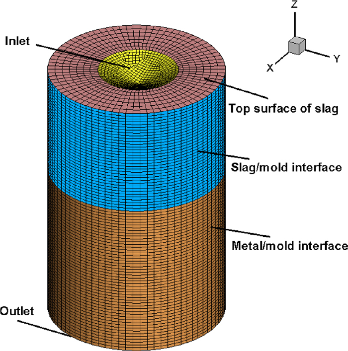
Finite volume mesh in ESR system (bottom of electrode, slag, metal). (Online version in color.)
| Parameter | Value |
|---|---|
| Applied current, A | 4500 |
| Volt, V | 58 |
| Vibrating amplitude, m | 0.003/0.045/0.006 |
| Vibrating Frequency, c/min | 0/5/10/15/20/60 |
| Temperature of cooling water in and out, K | 288/310 |
| Temperature of air, K | 308 |
| Heat transfer at the slag/mold wall, W/m2K | 486 |
| Heat transfer at the metal/mold wall, W/m2K | 414 |
| Heat transfer at the slag/air, W/m2K | 232 |
| Emissivity of top surface of slag | 0.6 |
| Interfacial tension between slag and metal, N/m | 0.9 |
The factory investigations on the comparison of traditional and vibrating electrodes in ESR system have been implemented at Shenyang Research Institute of Foundry in China, as displayed in Fig. 3. The typical vibration technology principle has been introduced to design the equipment of vibrating electrode. The position of vibration generating equipment, according to the principal of the laser amplitude sensor, is at the tip of beam in ESR furnace. The self-consumable electrode is made of Q235 carbon steel, which has the chemical composition (wt%) of C = 0.18%, M = 0.45% Si = 0.25%, S = 0.045%, P = 0.04%. The slag is composed of 75% calcium fluoride and 25% aluminum. The detailed geometry conditions are described in Table 3.
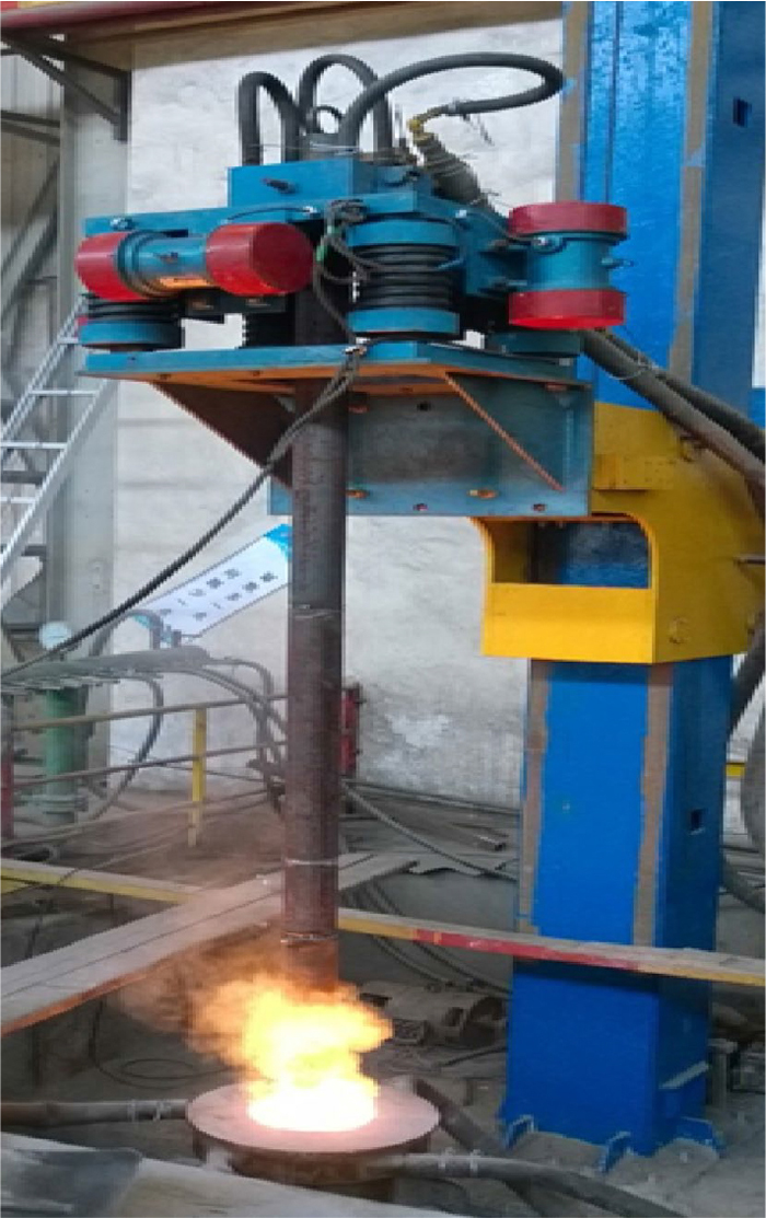
Photo of the ESR experiment with the vibrating electrode. (Online version in color.)
| Parameter | Value |
|---|---|
| Electrode diameter, m | 0.1 |
| Ingot diameter, m | 0.22 |
| Slag height, m | 0.14 |
| Immersion depth of electrode, m | 0.02 |
Figure 4 represents the comparison of measured temperature and calculated temperature in the slag at 2100 s. The position of observing line is of 0.08 m away from the center paralleling to the symmetry axis. The optional W3Re or W25Re thermocouple was used to measure the temperature at a frequency of ten minutes. From both the experiment and simulation results in the slag layer, the maximum temperature could be observed at z = 0.26 m along the line. Comparisons of the effect of frequency of vibrating electrode on melting rate between the experimental and calculated results at 2100 s are represented in Fig. 5. In this paper, the frequency fvib means the number of electrode vibrations per minute (c/min). With the purpose of recording the melting rate, the distance measuring equipment, which would be settled on the column, was used to record the upward displacement of beam. Furthermore, we have written self-compiled program to transform the displacement of beam into melting rating. From the picture, we could conclude that the melting rate will be significantly increased by using the vibrating electrode in the ESR system. As to the vibration of electrode, the heat exchange between the molten slag and metal droplets will be enhanced, leading to acceleration of electrode tip melting. In the meanwhile, the formation rating of metal droplets will be much quicker than without vibration due to the inertia force. Hence, the melting rate will be accelerated. Moreover, when the number of vibrating is not high, the melting rate with vertical vibrating increases significantly than that with horizontal vibrating. This could be obviously observed both in the experiment and simulation results. Hence, the experiment results are in a reasonable agreement with the calculations, which could verify the reliability of models. The deviation could be concluded by complexity of boundary conditions and physical properties during high temperature environment.
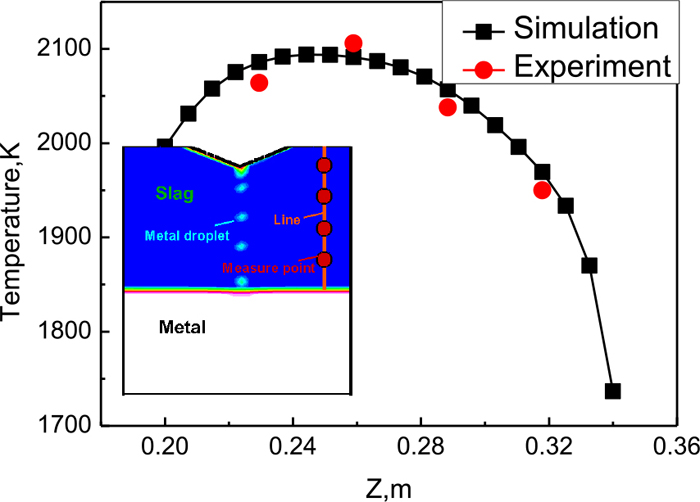
Comparison of measured temperature of the points and the numerical temperature of the line in the slag at 2100 s, fvib = 20 c/min, Avib = 0.003 m. (Online version in color.)

Comparison of variation of melting rate as a function of the frequency of vibrating electrode between the experimental observations and numerical results at 2100 s, Avib = 0.003 m. (Online version in color.)
The isometric vector field of current density and the thermal power density (Joule heating) distribution at the main section (x = 0) with the horizontal vibrating electrode are exhibited in Fig. 6(a). Since the electrical conductivity of metal is significantly larger than that of slag layer, the electric current in the molten metal will be penetrated easier that in the slag layer. Moreover, it is very interesting to observe that the outline of the maximum current density zone is in accordance with the configuration of the metal droplets in the slag layer. The minimum current density zone appears right beneath the slag/air interface adjacent to the inside wall of mold. As to the higher electrical resistance of slag, there is few current flow in the upper molten slag near the sidewall. Moreover, the skin effect is not prominent, since the analysis value of depth of the skin effect approaches to 84 mm near the ingot radius. In addition, the maximum zone of Joule heating which is in accordance with the highest domain of current density could be obtained. In the meanwhile, the Joule heating yielding in small electric resistivity of the steel could be negligible. Plenty of Joule heating is distributed at the front of moving direction of the metal droplets, which could be brought into metal pool finally. The profile of the Joule heating distribution and the falling motion of metal droplets could be captured synchronously in a periodical form.
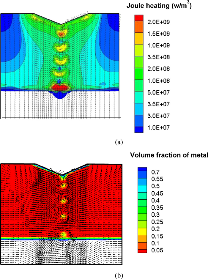
(a) Electric current (isometric vector) and Joule heating density distribution and (b) electromagnetic force and volume fraction of metal at the longitudinal section of the domain with the horizontal vibration of electrode (x = 0), the maximal of electromagnetic force is 918 N/m3, fvib = 20 c/min, Avib = 0.003 m. (Online version in color.)
Figure 6(b) exhibits the electromagnetic force field and volume fraction of metal in the longitudinal plane. The inward electromagnetic force resulted in a pinch effect as previously mentioned.11) The distribution of the electromagnetic force will vary simultaneously with the dropping metal droplets, which is similar to the current flow. It could be deduced that the electromagnetic force distributed at the vicinity of the metal droplets would hinder the dropping of the metal droplet. Furthermore, it can be found that the largest electromagnetic force appears around the metal droplets, not gathering close to the corner of the inlet of current flow in the bottom tip of electrode.
6.2. Temperature DistributionThe temperature distribution of the longitudinal plane (a) without vibrating, (b) with vertical vibrating and (c) with horizontal vibrating are shown in Fig. 7. The maximum temperature and depth of molten pool with vertical vibrating, no vibrating and horizontal vibrating in the slag layer are 2198 K, 2162 K, 2148 K and 0.108 m, 0.105 m, 0.1042 m, respectively. The key reason is that in vertical vibrating process, a large amount of Joule heating concentrates on the center of slag layer, resulting in generating molten droplets of larger diameter. Hence, it has the higher heat energy and deeper molten pool in vertical vibrating process. Additionally, we can observe that there are two high-temperature regions at the two sides of slag layer and a low-temperature region in the center of slag layer. The cooling system of the mold plays a paramount role in creating a large radial temperature gradient. It also makes the temperature of slag layer close to the mold much lower than that in the core. Nevertheless, since the temperature of fallen molten metal droplets is lower than the surrounding molten slag, the temperature of the slag layer in center zone will decrease. The temperature distribution changes beneath the bottom tip of the electrode. The variation of temperature distribution dominated by the dropping behavior of the metal droplets is ordered and periodic.
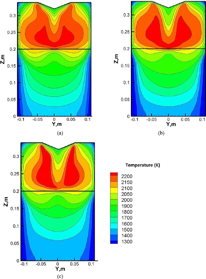
The temperature distribution of the longitudinal plane (a) without vibrating (b) with vertical vibrating and (c) with horizontal vibrating at 2100 s, fvib = 20 c/min, Avib = 0.003 m. (Online version in color.)
Figure 8 represents the evolution of the temperature profile in the middle horizontal plane of slag layer along the Y axis with three vibrating modes. From the picture, it can be seen that there is a lower temperature region in the center of slag layer in the three cases, as a result of the temperature of metal droplets lower than of slag layer. The higher temperature will be existed in the horizontal vibration of electrode ESR process, but this is not the maximum in the slag layer. The maximal temperature is located near the corner of electrode bottom in the upper slag layer, as there is plenty of Joule heating generated here, except for that generated through the metal droplets.
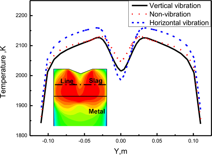
Evolution of the temperature profile in the middle horizontal plane of slag layer along the Y axis with three vibrating modes, fvib = 20 c/min, Avib = 0.003 m. (Online version in color.)
The evolution of average temperature gradient with different (a) amplitude and (b) frequency are displayed in Fig. 9. With the increasing amplitude and frequency, the average temperature gradients for both cases decreased. The increasing amplitude and frequency both mean that the vibration rate of electrode will be accelerated. Hence, the increasing of vibration rate of electrode will make the heat exchange between slag layer and electrode enhanced and inertia force enlarged, leading to the melting rate increased.
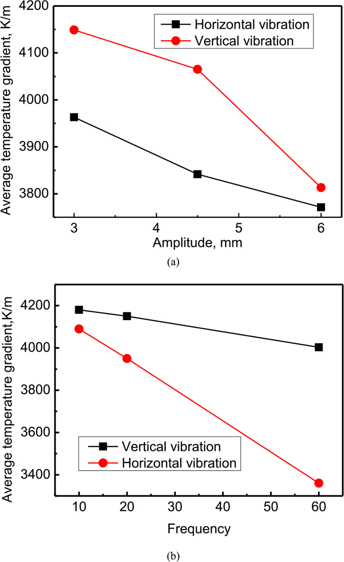
Evolution of average temperature gradient with different (a) amplitude and (b) frequency at 2100 s. (Online version in color.)
A description of the velocity and solidification fields of the molten slag and molten metal with (a) horizontal vibrating and (b) vertical vibrating in the ESR system are illustrated in Fig. 10. In order to show the vectors clearly in the molten pool, we particularly make this zone in white, actually in red. Focusing on the positions marked by the circles, we can see that the velocity distribution with vertical vibrating in the ESR process is symmetrical, while the velocity distribution with horizontal vibrating is asymmetrical. The main reason is that the horizontal vibrating could generate the radial velocity component. The shape of molten pool is a key factor to produce high quality metal and alloy in the ESR process. Generally, it is well to achieve a typical U-shaped metal pool profile. From the picture, we could see that the molten pool profile obtained in the horizontal vibrating electrode of ESR furnaces is shallower than that in the vertical vibrating electrode, which could be beneficial to directional solidification and restrain the macro-segregation significantly. Hence, the horizontal vibrating electrode in ESR furnaces is superior to the vertical vibrating electrode. Figure 11 shows the evolution of the velocity in the middle horizontal section of slag with three vibrating modes. It further verifies that the vertical and horizontal vibration in ESR system have the higher velocity than that with no vibrating (traditional electrode).
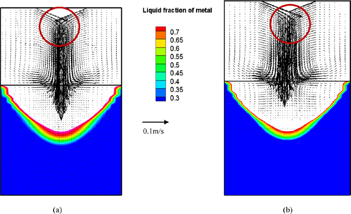
Velocity and solidification field of the molten slag and metal with (a) horizontal vibrating and (b) vertical vibrating in the ESR system at 2100 s, the maximal velocity is approximately 0.112 m/s, fvib = 20 c/min, Avib = 0.003 m. (Online version in color.)
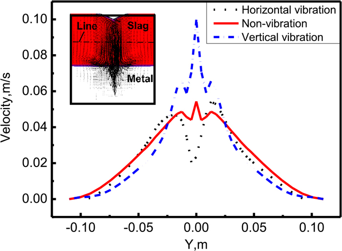
Evolution of the velocity in the middle horizontal section of slag with three vibrating modes, fvib = 20 c/min, Avib = 0.003 m. (Online version in color.)
Figure 12 displays the falling behavior of metal droplets in the main section (a) without vibrating (b) with vertical vibrating and (c) with horizontal vibrating. In order to show the vectors clearly in the molten pool, we particularly make this zone in white, actually in red. The equivalent diameter of metal droplets are 10.93 mm, 11.5 mm and 10.06 mm, respectively. The maximum diameter of metal droplets occur in the vertical vibrating process. The reason is that when the electrode goes downward, the metal droplets are in the fastest-growing condition. It will become larger until the electrode begins to go upward. When the electrode goes upward, the metal droplets will get rid of the tip of electrode and fall down into the molten pool due to the downward inertia force. The minimum diameter of metal droplet appears in the horizontal vibrating process, in which the formation of metal droplets is dominated not only by gravity force but also by horizontal inertia force. This will lead to the decreasing of the diameter of metal droplets. In the meanwhile, the falling metal droplets will move toward left and right. All the procedure is represented as a periodic behavior.
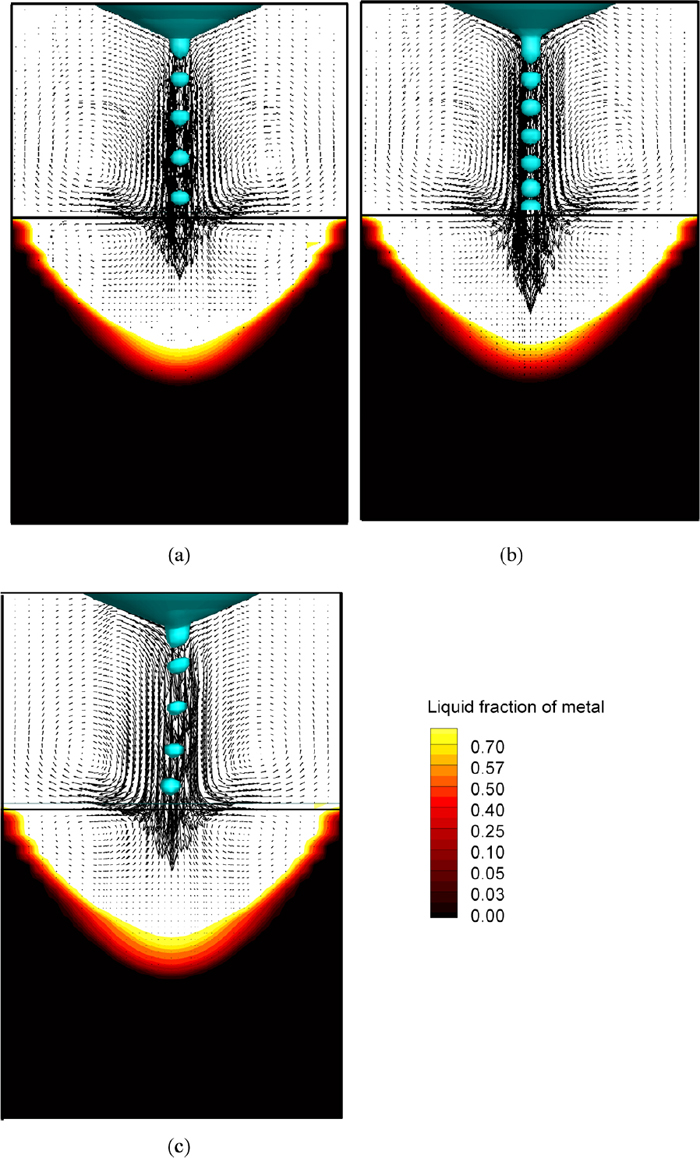
The falling motion of metal droplets of the main section (a) without vibrating (b) with vertical vibrating and (c) with horizontal vibrating, fvib = 20 c/min, Avib = 0.003 m. (Online version in color.)
The evolution of the equivalent diameter of the metal droplet, average temperature gradient, maximum depth molten pool and maximum temperature of molten pool with three modes of electrode at 2100 s are shown as Fig. 13. It is obvious that the horizontal vibrating ESR process can generate smaller metal droplets, which provide less energy (heat plus momentum) into the metal pool, constitute a shallower pool and a lower average temperature gradient, and finally be beneficial to the quality of steel. There is the minimum temperature in the middle of slag layer with the horizontal vibration of electrode compared to the other two cases. The reason for that is the distribution of Joule heating with horizontal vibration of electrode will be scattered in terms of the longitudinal component of velocity. Meanwhile, it gets the lower temperature ingredient when the heat exchange between slag layer and mold will be enhanced with the longitudinal component of velocity. However, since there are larger metal droplets produced and electricity currents are prone to go through the low electrical resistance, the Joule heating generated by the vertical vibration of electrode ESR process will be increased and concentrated, yielding in the higher maximum temperature of slag layer and the maximum temperature ingredients.

Evolution of the equivalent diameter of the metal droplet, average temperature gradient, maximum depth molten pool and maximum temperature of molten pool with three motion modes of electrode at 2100 s, fvib = 20 c/min, Avib = 0.003 m. (Online version in color.)
In this paper, it is the first time to compare the thermo-electromagneto-hydrodynamic fields with the vibrating and traditional electrodes in the ESR furnace by a transient 3D coupled model. The conclusions are as follows:
(1) It is verified that the melting rating can be increased in the vibrating ESR process. The small scale factory experiment is conducted, and a reasonable agreement between the experimental observations and numerical results is obtained.
(2) The variation of temperature distribution dominated by the dropping behavior of the metal droplets is ordered and periodic. With the increasing amplitude and frequency, the average temperature gradients decreased for both cases.
(3) Through the comparisons between three vibrating modes, the horizontal vibrating ESR process can generate smaller metal droplets, which provide less energy (heat plus momentum) into the metal pool, constitute a shallower pool and a lower average temperature gradient, and finally be beneficial to the quality of steel.
The authors’ gratitude goes to National Natural Science Foundation of People’s Republic of China [NO. 51275320 and 51210007] and Fundamental Research Funds of People’s Republic of China for the Central Universities (N150204004).
Am: mushy zone constant
Ax: x component of magnetic flux density (T)
Ay: y component of magnetic flux density (T)
Az: z component of magnetic flux density (T)
Avib: amplitude of vibration(m)
Cp: heat capacity (J/(kg·K))
fH: electric current frequency (Hz)
fvib: frequency of vibration (c/min)
h: sensible enthalpy (J/kg)
href: reference enthalpy (J/kg)
H: enthalpy (J/kg)
Irms: root mean square current (A)
k: turbulent kinetic energy (m2/s2)
ke: effective thermal conductivity (W/(m·K))
L: latent heat (J/kg)
Q: Joule heating (W/m3)
Qtotal: the total value of Joule heating (W/m3)
R: radius (m)
Rmold: radius of the inner mold (m)
Sk: source term of solidification in the turbulent kinetic energy equation (m2/s3)
Sε: source term of solidification in the dissipation rate of turbulent kinetic energy equation (m2/s3)
t: time (s)
T: temperature (K)
Tref: reference temperature (K)
Ts: solidus temperature (K)
V: volume of slag layer(m3)
β: thermal expansion coefficient (1/K)
δ: electromagnetic skin thickness (m)
ε: dissipation rate of turbulent kinetic energy (m2/s3)
η: power efficiency
μ0m: vacuum permeability of metal (H/m)
μeff: effective viscosity (Pa·s)
ρ: density (kg/m3)
ρmetal: electric resistance of metal (Ω·m)
σ: electrical conductivity (1/(Ω·m))
φ: electric potential (V)