Abstract
Recently, 5% Mn steel has been focused on as one of the promising candidates for third generation AHSS by showing an excellent TS (Tensile Strength)-El (Elongation) relationship. The excellent TS-El relationship is brought about by a large volume fraction of retained austenite through the enrichment of austenite stabilizing elements such as C and Mn in retained austenite. The effect of the microstructure of mother hot band on the changes in microstructure and mechanical properties was compared with the intercritical annealing time in this study. The steel containing about 10% of retained austenite in a mother hot band exhibited a higher volume fraction of retained austenite and higher strength after intercritical annealing. On the other hand, the steel which did not contain retained austenite in a mother hot band exhibited excellent TS-El combination. The difference of work hardening behavior in these steels was analyzed and thought to be brought about by the difference of transformation behavior during deformation determined by the stability of retained austenite affected by Mn concentration. Although the precipitation of cementite was intended to effectively act as a nucleus of reverted austenite formation and to accelerate its formation, this affirmative result was not obtained. Since the volume fraction of cementite in a short annealing time is nearly the same in all hot rolling conditions, the higher volume fraction in hot band did not act to increase retained austenite during intercritical annealing.
1. Introduction
Reducing the weight of the automobile body while maintaining sufficient safety by using high strength steel sheet is an important concern of automakers from the viewpoint of both fuel efficiency and crash worthiness.1) When the high strength steel sheet is applied to automobile parts, high ductility is demanded to enable the press forming for complex shape of parts.
The concept of advanced high strength steel sheets (AHSS) such as DP (Dual Phase)2) and TRIP (Transformation Induced Plasticity)3) steel sheets were developed and 980 and 1180 TS grade steels have been progressively applied to body parts to satisfy these requirements recently.4,5,6,7) However since the combination of tensile strength (TS) and total elongation (T-El) of these steels is limited to about TSxT-El=20000 MPa·%, the development of high strength steel sheet with higher El has been strongly demanded. Recently, steel sheet with much higher El has been focused on as the third generation AHSS. Q&P (Quench & Partitioning) steel8) and medium Mn steel9,10,11,12,13,14,15,16,17,18) are promising candidates for the third generation AHSS. In this investigation, medium Mn steel is focused on, because an excellent TS-El relationship is expected due to a large volume of retained austenite.
Medium Mn steel can retain a lot of austenite by reheating to an (α+γ) intercritical temperature through the enrichment of austenite stabilizing elements such as C and Mn in reverted austenite. It is reported that an excellent TS-El relationship is achieved by the TRIP effect of the large volume fraction of retained austenite. Research on this material has been performed for hot rolled sheet9,10,11,12,13,14,15,16) and cold rolled sheet.17,18) The stress-strain curve of these steels is different because of the difference of the microstructure. Hot rolling and intercritical annealed steel shows a lamellar type structure of annealed martensite and austenite and continuous yielding behavior, while cold rolling and intercritical annealed steel shows ultrafine equiaxised microstructure and several percent of yield point elongation. Although a lot of papers on medium Mn steel have been published, the effect of microstructure on the mechanical properties and its mechanism before intercritical annealing has not been thoroughly discussed. Thus the effect of the microstructure of the mother hot band on the changes in microstructural and mechanical properties as compared with the intercritical annealing time was investigated. In addition, the mechanism for the excellent TS-El relationship of this steel is discussed through an analysis of the stability of retained austenite.
2. Experimental Procedure
The steel used in this study was 0.2C-2Si-5Mn (mass%) steel with the chemical composition shown in Table 1. 50 kg steel was melted in a vacuum atmosphere. The ingot was hot forged to 50 mm square and rough hot rolled into 30 mm in thickness, followed by finish hot rolling to 3.0 mm. The reheating temperature (RT) and finishing hot rolling temperature (FT) was 1200°C and 870°C respectively. In order to change the conditions of hot rolled sheets, three kinds of cooling and reheating conditions, as shown in Fig. 1, were carried out. The aim of Condition I was to obtain a martensitc microstructure by rapid cooling of 95°C/s to room temperature from finish rolling. The aim of condition II was to obtain a bainitic microstructure by keeping the sheet at 360°C for 60 min (CT) after hot rolling. The steel of condition II was reheated to 575°C for 60 min to shed light on the effectiveness of cementite as a nucleolus of reverted austenite and designated as condition III. These hot rolled sheets were heat treated in a salt bath and air cooled to room temperature. The heat treatment was conducted at 675°C for 1 min to 100 min, the temperature at which the equivalent ferrite and austenite ratio is 1:1. The software to calculate the equilibrium phase fraction was Thermo-Calc. (Data base; TCFE6).
Table 1. Chemical composition of steel used (mass%).
| C | Si | Mn | P | S | Al | N | O |
|---|
| 0.19 | 1.98 | 4.99 | 0.005 | 0.0018 | <0.002 | 0.0038 | 0.0006 |
Tensile tests were carried out using JIS No. 14B specimens taken in the longitudinal direction and ground to 2 mm in thickness. The gauge length and width of the tensile specimen were 20 mm and 7 mm respectively. The tensile rate was 4 mm/min. The engineering stress-strain curve was measured by an extensometer with a GL of 12.5 mm.
The microstructure and retained austenite were evaluated by FE-SEM (Field Emission-Scanning Electron Microscope). FE-SEM/EBSD:OIM system (Electron Back Scattering Diffraction: Orientation Imaging Microscopy system), TEM (Transmission Electron Microscope). Mn and Si partitioning behavior was studied by Cs-STEM/EDX (Corrector Spherical aberration-Scanning TEM/Energy Dispersive X-ray Spectroscopy). The volume fraction of retained austenite, the carbon concentration in retained austenite (Cγ) and the volume fraction of carbide were quantified by SR-XRD (Synchrotron Radiation-X Ray Diffraction).19,20) Specimens were electro-polished to 0.3 mmϕ after an electric discharge cutting to 0.5 mmϕ × 30 mm. BL19B2 in SPring-8 with 35keV input energy and a Debye-Scherrer Camera were used for X-ray transmission diffraction. The volume fraction of retained austenite and carbide were measured from the integration of the intensities of the scattering 2θ angle from 5 degrees to 58 degrees. The scattering 2θ angle covers from (110) to (730) for α phase, from (111) to (931) for γ phases and from (121) to (334) for carbide, Fe3C. Cγ was estimated by substituting the lattice constant aγ measured by SR-XRD into the following Eq. (1) proposed by Dyson et al.21)
|
a
γ
=3.5780+0.0330(%
C
γ
)
+0.00095(%M
n
γ
)+0.0220(%
N
γ
)
| (1) |
where %Mn
γ and %N
γ represent the concentrations of the respective individual elements (mass%). For convenience, the amounts of the added alloying elements were used for these elements in this study.
In order to analyze the transformational behavior of retained austenite measured against tensile strain, tensile strain within the range of uniform elongation was given for small tensile specimens (t=1, w=5, GL=12.5). The specimen for SR-XRD was cut from the strained specimens and the volume fraction of retained austenite was measured according to the above mentioned XRD measurement procedure.
3. Experimental Results
3.1 Microstructure Evolution of Hot Band and Intercritical Annealed Steel Sheet
SEM images of hot bands of condition I through III are shown in Fig. 2. The microstructure of condition I was lath martensitic structure. The microstructure of condition II was bainitic structure, which was brought about by coiling simulation at bainite transformation temperature range. Many fine cementites were observed at the bainite lath boundary in condition III.

Since the classification of retained austenite in matrix was not clear by SEM images, FE-SEM/EBSD observation was carried out. As the representative example of intercritical annealed sheets, EBSD IPF maps annealed at 675°C for 30 min are shown in Fig. 3. All of the intercritical annealed structure, as shown in Fig. 3, exhibited a lamellar type structure of annealed martensite and retained austenite in all of hot rolling conditions. Nearly the same crystallographic orientated retained austenite was existed in one prior austenite grain. The volume fraction of the retained austenite obtained in Fig. 3 was approximately 25%. This value is smaller than the result evaluated by SR-XRD, mentioned later. The discrepancy comes from the difference of penetration depth between EBSD and SR-XRD. The penetration depth of the electron beam in the EBSD is ~10 nm, while a transmitted value of 0.3 mmϕ was measured in the case of SR-XRD. Akamizu et al reported that the retained austenite near the surface decreases for the following reasons: (1) transformation to martensite by the polishing strain, (2) the loss of space constraint by surrounding grains.22) The difference of volume fraction in both methods must be due to the above mentioned reasons.

Figure 4 shows TEM and Cs-STEM images of intercritical annealed steel at 675°C for 30 min for condition I. Figures 4(a), 4(b), 4(c) and 4(d) show Cs-STEM bright field image, TEM dark field image, a Cs-STEM Mn mapping image and the Cs-STEM line analysis result respectively. As shown in Figs. 4(a) and 4(b), retained austenite whose width and length are approximately 150 and 500 nm was located at the lath boundary. As shown in Fig. 4(c), enrichment of Mn was recognized in retained austenite identified by a TEM dark field image. The distribution of Mn and Si along the line perpendicular to retained austenite and annealed martensite is shown in Fig. 4(d). The Mn content in the Mn-rich and –lean region is 8–10% and 2% respectively, while the ferrite former element, Si, showed the reverse behavior. Through these observations it was confirmed that retained austenite contains as high as 10% enriched Mn and a lower amount of Si than added content of 2%.
3.2 Precipitation Behavior of Cementite
Effects of hot rolling conditions and intercritical annealing times on the cementite precipitation behavior are shown in Fig. 5. The volume fraction of cementite of hot band for conditions I and II were smaller than the analyzed limit, while in condition III, it was 2.3 vol.%. About 3% of cementite were observed in a short annealing time, which decreases gradually with increasing annealing time.
3.3 Volume Fraction of Retained Austenite
Effects of hot rolling conditions and intercritical annealing time on the changes of volume fraction of retained austenite are shown in Fig. 6. As far as hot bands are concerned, the volume fraction of retained austenite of conditions I was 2.5%, while in condition II, it was 11.7%.

The volume fraction of retained austenite increased with annealing time. The maximum volume fraction of retained austenite was obtained for the longest annealing time, 100 min, in all hot rolling conditions. Condition II exhibited a higher volume fraction than conditions I and III. The higher volume fraction of retained austenite in condition II is thought to be obtained by the higher volume fraction in its hot band. As mentioned exactly in 4.3, grain size of retained austenite of ConditionII was larger than it of ConditionI.Although in condition III, it was intended that cementite effectively act as the nucleus of reverted austenite formation and accelerate its formation, this affirmative result was not obtained. Since the volume fraction of cementite in a short annealing time is nearly the same as in all hot rolling conditions, the higher volume fraction of cementite in condition III in its hot band did not act to increase retained austenite during intercritical annealing.
3.4 Tensile Properties
The mechanical properties of hot bands are listed in Table 2. The highest TS, 1855 MPa, was obtained for condition I and then, 1617 MPa for condition II, which are reflected the microstructure, martensite or bainite. Condition III, which was tempered at 575°C, showed the lowest value at 1064 MPa. Their YS were 1269 MPa, 914 MPa, and 859 MPa for conditions I through III. TSxEl as an index of the strength-elongation relationship was the highest in condition II due to the highest volume fraction of retained austenite. As for the yield ratio (YR=YS/TS), condition I showed a low value of 0.68, and condition II showed a lower value of 0.57. These results are thought to originate in the microstructure, that is, martensite in condition I and the existence of retained austenite in condition II. Condition III showed the highest value, 0.81, which is brought about by the tempering.
Table 2. Mechanical properties of hot rolled steel before intercritical annealing.
| Condition | 0.2% YS
[MPa] | TS
[MPa] | U-El
[%] | T-El
[%] | TSxT-El
[MPa·%] | YR |
|---|
| I | 1269 | 1855 | 4.8 | 7.2 | 13356 | 0.68 |
| II | 914 | 1617 | 6.1 | 16.1 | 26034 | 0.57 |
| III | 859 | 1064 | 9.1 | 19.4 | 20645 | 0.81 |
Figure 7 shows the effects of hot rolling conditions and intercritical annealing time on tensile properties. The tensile properties of conditions I, III and II are clearly different. TS increased with an increase in annealing time longer than 10 min. Condition II showed higher TS in all annealing times. YS of conditions I and III decreases with an increase in annealing time. While condition II showed a low YS, 650 MPa, from a short annealing time. YR was as high as 0.8 in short annealing times for conditions I and III and decreased to 0.6 with an increase in annealing time. In contrast, condition II showed a low YR of 0.6 from a short annealing time. Total elongation (T-El) and uniform elongation (U-El) increased with an increase in annealing time. Conditions I and III showed a higher value than condition II.

Changes in mechanical properties with annealing time are mainly related to the changes in volume fraction of retained austenite. TS and elongation increased with an increase in annealing time. This behavior accorded with the increase in volume fraction of retained austenite and with an increase in annealing time. It is well known that TSxU-El increases with an increase in volume fraction of retained austenite due to the TRIP effect.23) The result of the elongation obtained in this experiment comes from the TRIP effect due to the higher volume fraction of retained austenite during the longer annealing time. The decrease in YS with annealing time in conditions I and III is brought about by a decrease in dislocation density through the annealing of martensite.
4. Discussion
4.1 Work Hardening Behavior
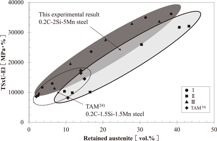
The relationship between TSxU-El, which is an index of the strength-elongation relationship, and the volume fraction of retained austenite is shown in Fig. 8. Their relationship of conventional low Mn-TRIP steel is plotted in addition to the data obtained in this experiment. The steel, named TAM (TRIP Annealed Martensite), was referred in order to compare it with the result of this experiment, because TAM has the same microstructure as in this experiment, consisting of annealed martensite and film-like retained austenite existing at the annealed martensite lath.24) The reason why TSxU-El, but not TSxT-El, was adopted as the index of the TS-El relationship is the different shape of the tensile specimen. TAM showed a maximum value of 15% of retained austenite and 15000 MPa% of TSxU-El, while 5%Mn steel exhibited higher than 35% of retained austenite and higher than 30000 MPa% of TSxU-El. This result means that an excellent TS-El relationship of 5%Mn steel can be obtained by the existence of a high volume fraction of retained austenite. However, a difference in the TSxU-El level among the hot rolling conditions was observed. That is, conditions I and III show a higher level than condition II. The difference of the TSxU-El level at the same volume fraction of retained austenite is thought to result from the difference of the stability of retained austenite.
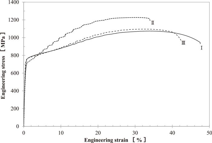
The effect of hot rolling conditions I through III on the engineering stress-strain curves of 30 min intercritical annealed steels is shown in Fig. 9. Serration related to localized deformation due to the TRIP effect was found in all steels. The most intensive serration was observed in condition II. The mechanical properties and volume fraction of retained austenite of these steels are listed in Table 3. The n value was calculated for two kinds of strain range; one is 5%–15% and the other is 10%–20%. Hot rolling conditions I and III showed a high n value at the high strain range, while condition II was high as 0.36 and 0.37 in both strain ranges.
Table 3. Mechanical properties and retained austenite volume fraction and Ms of 30 min annealed steel.
| Condition | 0.2% YS | TS | U-El | T-El | n value | γR |
|---|
| [MPa] | [MPa] | [%] | [%] | 5%–15% | 10%–20% | [vol.%] |
|---|
| I | 681 | 1079 | 32.4 | 45.1 | 0.225 | 0.359 | 31.5 |
| II | 627 | 1228 | 25.8 | 26.6 | 0.361 | 0.372 | 40.6 |
| III | 719 | 1087 | 30.3 | 38.0 | 0.251 | 0.364 | 27.8 |
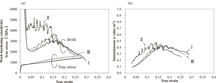
The work hardening behavior was also different between conditions I and III, and condition II. In order to analyze the work hardening behavior, changes in the work hardening rate, dσ/dε, and the instantaneous n value, n*, against the true strain is calculated and revealed in Figs. 10(a) and 10(b). The instantaneous n value (n*) was calculated according to Eq. (2).
As shown in Fig. 10(a), conditions I and III exhibited a low dσ/dε in the low strain range and increased with the strain, while condition II showed a high dσ/dε from a low strain range and decreased gradually with an increase in strain. As shown in Fig. 10(b), conditions I and III exhibited their peak value at a high strain range, while condition II showed peak n* value at a lower strain range. The behavior of dσ/dε and n* in conditions I and III is different from that in condition II. This difference means that the transformation behavior of retained austenite is different between them.
4.2 Stability of Retained Austenite with Strain
Since nearly same mechanical property and work hardening behavior were obtained in conditions I and III, the steel of condition I was selected as a representative. Accordingly the comparison between steels annealed for 30 min of conditions I and II were carried out. In order to investigate the transformation behavior with tensile strain, the volume fraction of retained austenite for pre-strained tensile specimen was measured by SR-XRD. The change in volume fraction of retained austenite compared with pre-strain is shown in Fig. 11. The number indicated in parenthesis is the strain induced transformation factor, k, which is the index of the stability of retained austenite. A low k value means a high stability of retained austenite.25,26) The k value was calculated by the Eq. (3);
where f
γ0 is the initial volume fraction of the retained austenite, and f
γε is the volume fraction of the retained austenite after applying plastic strain,
ε. In order discuss about the stability of retained austenite with strain, k value shown in
Eq. (4) was used.
The retained austenite decreases with tensile strain. But their dependence on strain is different in two kinds of hot rolling conditions I and II. Condition I showed a low k in a low strain range and shifted to a high k in a high strain range, while condition II showed a high k in a low strain range and shifted to a lower k in a high strain range. These results mean that retained austenite is the most stable in the low strain range of condition I and the most unstable in the low strain range of condition II. This behavior corresponded with the behavior of dσ/dε and n* shown in Fig. 10. In order to discuss the stability of retained austenite, the martensite start temperature (Ms), which is known as the index of it,27,28) is calculated.
Ms was calculated for the steels shown in Fig. 11 and is given in Table 4. The Ms was calculated according to Eq. (5).29) Cγ, Mnγ, Siγ and Alγ are C, Mn, Si and Al concentration in retained austenite. Cγ and Mnγ are used as the value measured by SR-XRD and Cs-STEM/EDX respectively. For convenience, the amounts of the added alloying elements were used for Siγ and Alγ.
|
Ms(°C)=539-423(%Cγ)-30.4(%Mnγ)
-7.5(%Siγ)+30(%Alγ)
| (5) |
Table 4. C
γ (carbon content in retained austenite) and Mn
γ (Mn content in retained austenite) and calculated Ms temperature of intercritical annealed steel at 675°C for 30 min for condition I and II.
| Condition | Cγ [mass%] | Mnγ [mass%] | Ms [°C] |
|---|
| I | 0.52 | 9.9 | 2.8 |
| II | 0.47 | 7.5 | 98.2 |
Condition I showed a lower Ms than condition II because of the higher content of austenite stabilizing elements C and Mn, which implies retained austenite in condition I is more stable than condition II. Higher C and Mn content in retained austenite in condition I is thought to be come from the different volume fraction. When the intercritical annealing time is same, diffusion and enrichment of C and Mn to retained austenite is same. Accordingly, the enrichment of austenite former elements is higher in smaller austenite volume fraction in condition I. The difference of the content of austenite stabilizing elements in the two conditions results in a difference of transformation behavior as measured against tensile strain through the difference of Ms. However, the Ms of condition II was higher than room temperature, which indicated the possibility of transformation during the cooling process from intercritical annealing. Ms decreases with a decrease in austenite grain size. The effect of the grain size of retained austenite is not considered in Eq. (5). It is reported that when the grain size of retained austenite is as small as the submicron level, the Ms temperature decreases more than 100°C.30,31) As the width of the retained austenite in this study was submicron size, the Ms of condition II is thought to be lower than room temperature.
4.3 Enrichment of Manganese in Retained Austenite
In order to confirm the enrichment of Mn in retained austenite, the measurement of Mn content was carried out by Cs-STM/EDX. The effect of hot rolling conditions I and II on the Mn mapping image and a points analysis of 30 min intercritical annealed steels are shown in Fig. 12. As shown in the Mn mapping images, Mn is enriched in retained austenite. Condition I showed even enrichment, while Mn is locally enriched at the boundary of the α and γ interface in condition II. The average and standard deviation of conditions I and II were 9.9%, 7.5%, 0.33 and 0.31 respectively. These results clarified that condition I showed a higher and smaller scattered Mn content than condition II. Inoue et al.30) discussed about the morphology of two types of retained austenite, although the Mn content in the retained austenite is not discussed. They reported that film like austenite is formed through the growth of the untransformed austenite, while island-type austenite was observed in the fully-quenched specimens. The morphology shown in Fig. 12 is resembled with the results of them. The lower Mn region in condition II shown in Fig. 12 must be formed by the growth of the existing austenite, while the higher Mn content in the retained austenite of condition I is possibly due to enhancement in nucleation of the austenite during intercritical annealing. Not only Mn content but also size of them must be affected by the different morphology of the two types of retained austenite.

The difference in Mn distribution in retained austenite brought about the difference of transformation behavior. That is, the stable retained austenite in condition I brought about the high work hardening rate and n* to the high strain range in the tensile test, while condition II showed the martensite transformation at a low strain range due to the instability of retained austenite and brought about a low work hardening rate and n* in a low strain range. In addition, the retained austenite disperses finely in condition I. The refinement of retained austenite contributes to stabilize retained austenite through the decrease of Ms.31,32) From above mentioned discussion, the difference of work hardening behavior is brought about by the difference of enrichment of austenite former elements in retained austenite and grain size of retained austenite.
5. Conclusion
By using 0.2C-2Si-5Mn steel, the effect of the microstructure of the mother hot bands on the changes in mechanical properties and transformation behavior with intercritical annealing time and the mechanism for the excellent strength-elongation relationship of this steel were discussed and the following results were obtained.
(1) Excellent strength-elongation combination was obtained for the intercritically annealed steels within 30 to 100 min. The highest values were TS=1080 MPa, T-El=41% and TSxT-El=44600 MPa·% for steels which did not contain retained austenite in their mother hot band and TS=1270 MPa, T-El=35% and TSxT-El=44100 MPa·% for steels which contained about 10% of retained austenite in their mother hot band.
(2) The steels with a high Mn concentration in their retained austenite exhibited a TRIP effect in a high strain range, while the steels with a relatively low Mn concentration in retained austenite exhibited a TRIP effect in a low strain range. This result implies that the transformation behavior during deformation is determined by the stability of retained austenite which is affected by Mn concentration.
(3) Although the precipitation of cementite was intended to effectively act as a nucleus of reverted austenite formation and to accelerate its formation, this affirmative result was not obtained. Since the volume fraction of cementite in a short annealing time is nearly the same in all hot rolling conditions, the higher volume fraction in hot band did not act to increase retained austenite during intercritical annealing.
References
- 1) K. Saito: Materia Jpn., 53 (2014), 584.
- 2) S. Hayami and T. Furukawa: Proc. Micro Alloying 75, Union Carbide Corp., New York, (1977), 311.
- 3) V. F. Zackay, E. R. Parker, D. Fahr and R. Bush: Trans. Am. Soc. Met., 60 (1967), 252.
- 4) M. Ohta, Y. Taniguchi, Y. Yamamori and T. Tanaka: J. Soc. Automot. Eng. Jpn., 68 (2014), 139.
- 5) N. Fujita, K. Kusumi, K. Matsumura, T. Nonaka and T. Tomokiyo: Nippon Steel Tech. Rep., 393 (2012), 99.
- 6) T. Kimura: Kobe Steel Eng. Rep., 61 (2011), 49.
- 7) K. Sugimoto and J. Kobayashi: J. Jpn. Soc. Technol. Plast., 54 (2013), 949.
- 8) J. Speer, D. K. Matlock, B. C. DeCooman and J. G. Schroth: Acta Mater., 51 (2003), 2611.
- 9) R. L. Miller: Metall. Trans., 3 (1972), 905.
- 10) T. Furukawa, H. Huang and O. Matsumura: Mater. Sci. Technol., 10 (1994), 964.
- 11) T. Furukawa and O. Matsumura: Netsu Shori, 37 (1997), 204.
- 12) T. Hanamura, S. Torizuka, A. Sunahara, M. Imagumbai and H. Takechi: ISIJ Int., 51 (2011), 685.
- 13) C. Wang, J. Shi, C. Y. Wang, W. J. Hui, M. Q. Wang, H. Dong and W. Q. Cao: ISIJ Int., 51 (2011), 651.
- 14) H. F. Xu, J. Zhao, W. Q. Cao, J. Shi, C. Y. Wang, J. Li and H. Dong: ISIJ Int., 52 (2012), 868.
- 15) C. Zhao, C. Zhang, W. Cao, Z. Yang, H. Dong and Y. Weng: ISIJ Int., 54 (2014), 2875.
- 16) H. Xu, W. Cao, H. Dong and L. Li: ISIJ Int., 55 (2015), 662.
- 17) D. W. Suh, S. J. Park, T. H. Lee, C. S. Oh and S. J. Kim: Metall. Mater. Trans. A, 41A (2010), 397.
- 18) D. W. Suh, J. H. Ryu, M. Joo, H. S. Yang, K. Lee and H. K. D. H. Bhadeshia: Metall. Mater. Trans. A, 44A (2013), 286.
- 19) E. Nishibori, M. Takata, K. Kato, M. Sakata, Y. Kubota, S. Aoyagi, Y. Kuroiwa, M. Yamakata and N. Ikeda: Nucl. Instrum. Phys. Res., 467–468 (2001), 1045.
- 20) M. Takata, E. Nishibori, K. Kato, Y. Kubota, Y. Kuroiwa and M. Sakata: JCPDS-International Center for Diffraction Data 2002, Advances in X-ray Analysis, 45 (2001), 377.
- 21) D. J. Dyson and B. Holmes: J. Iron Steel. Inst., 208 (1970), 469.
- 22) H. Akamizu, K. Saitou, S. Ikeda, K. Makii and S. Takaki: Kobe Steel Eng. Rep., 52 (2002), 43.
- 23) O. Kawano, J. Wakita, K. Esaka and H. Abe: Tetsu-to-Hangané, 82 (1996), 232.
- 24) S. Hashimoto, T. Kashima, S. Ikeda and K. Sugimoto: Tetsu-to-Hagané, 88 (2002), 42.
- 25) S. Sugimoto, N. Usui, M. Kobayashi and S. Hashimoto: ISIJ Int., 32 (1992), 1311.
- 26) K. Sugimoto, M. Kobayashi and S. Hashimoto: Metall. Mater. Trans. A, 23A (1992), 3085.
- 27) I. Tamura: Tetsu-to-Hagané, 56 (1970), 429.
- 28) K. Shibata: Netsu Shori, 32 (1992), 2.
- 29) J. Mahieu, J. Maki, C. DeCooman and S. Claessens: Metall. Mater. Trans. A, 33A (2002), 2573.
- 30) T. Inoue, T. Egashira, J. Tobata, D. Akama, N. Nakata, T. Tsuchiyama and S. Tkagi: CAMP-ISIJ, 28 (2015), 787.
- 31) H. S. Yang and H. K. D. H. Bhadesia: Scr. Mater., 60 (2009), 493.
- 32) S. Lee and B. C. DeCooman: Metall. Mater. Trans. A, 44A (2013), 5018.