Regular Article
Additional Slag Doors for Increased EAF Efficiency: A Conceptual Study
2017 Volume 57 Issue 8 Pages 1394-1399
Details
2017 Volume 57 Issue 8 Pages 1394-1399
The paper presents a conceptual study on modification of the electric arc furnace (EAF) slag doors in order to allow removal of the excess slag from the EAF. The idea behind additional slag doors is to allow deslagging of the bath in certain unfavorable cases when the slag height is too great. Slags which exceed the optimal height cause unnecessary refractory corrosion and additional energy losses. The study proposes symmetric slag doors comprised of two hatches, i.e. upper and lower. The upper hatch is intended to decrease the slag height to the optimal level, while the lower hatch can be used to completely deslag the EAF at tapping. In this manner, tilting of the EAF is not necessary. A conceptual study is performed focusing on the effects of the proposed doors on EAF energy performance. The study shows that implementation of the proposed solution could lead up to 1–2% efficiency improvement and approximately 2–3 minute tap-to-tap time decrease in comparison to the conventional slag doors.
In this paper a conceptual study on modification of the electric arc furnace (EAF) slag doors, in order to allow removal of the excess slag (ES) from the EAF, is performed. The idea of additional slag doors is to allow deslagging of the EAF in certain unfavorable conditions when the slag height is too great and extends over the arcs. Whether the slag exceeds its optimal height, i.e. being greater than the length of the arcs, unnecessary refractory corrosion and additional energy losses appear.
Slag doors are a part of an EAF and are used to sample the bath and to deslag the furnace. In normal operation, an EAF equipped with a standard slag doors is tilted for 15 to 20° in order to deslag the bath at tapping1) or for 3° to remove the excess slag during the operation. The movement of the EAF causes mechanical stress on the furnace structure and increases tap-to-tap time. Moreover, openings around the door allow air infiltration into the furnace or gas emissions from the furnace, depending whether the EAF pressure is negative or positive. Furthermore, furnace operators have no control over slag discharge from the door.
Innovations related to slag doors as well as concepts to remove an optimum amount of excess slag are seldom reported. Most innovations focus on sealing the openings around the slag door due to its negative effects. Wunsche2) invented a door closure element that seals the openings air-tight. Miani3) invented a slag door including at least one moveable water cooled panel that covers the opening around the door and can remove the slag around it. These innovations do not allow removal of a determined amount of slag based on bath and slag heights.
The proposed innovation relates to additional slag doors, placed symmetrically around the EAF, which are schematically shown in Figs. 1 and 2. Figures 1(a) and 2(a) show the placement of the proposed doors and slag line position for spout tapping (ST) and eccentric bottom tapping (EBT) EAFs. In order to show the effect of the additional slag doors on the slag line position in comparison to the EAF with conventional slag doors, Figs. 1(b) and 2(b) are shown.

Schematic representation of the proposed slag doors for spout tapping EAF, a) proposed slag door, b) conventional slag door.

Schematic representation of the proposed slag doors for EBT EAF, a) proposed slag door, b) conventional slag door.
As can be seen, each door set consists of at least two hatches placed vertically. Upper hatches are intended to remove the excess slag during EAF operation and at tapping, while the lower hatches are used together with the upper hatches to completely deslag the EAF. The bottom edge of the lower hatch should be placed slightly above the maximum steel bath height at tapping. In this manner, only slag is removed when deslagging. All hatches on the same level (upper or lower) are supposed to be opened simultaneously, except when the EAF is continuously charged with DRI. In that case, only the slag doors with the greatest distance to the DRI feed path should be opened assuring minimum probability of DRI discharge.
Figure 3 presents the EBT EAF equipped with the proposed doors and their placement around the furnace circumference from the top view.
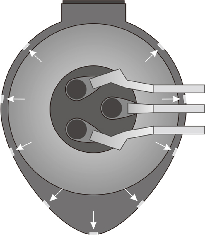
Top view of the proposed slag doors for spout tapping EAF.
Each door has its own slag discharge path. The purpose of the slag discharge paths is twofold; first, to convey the slag into the container; and second, to prevent the contact between the slag and the EAF shell and its damage. As can be seen in Fig. 4, each hatch is placed on the rails, mounted inside the upper brick, allowing its movement in radial direction, and is protected by a barrier at the inner-upper side of the EAF. Figures 4(a) and 4(b) show the inside and the outside views of the proposed door hatch (slag door not shown).
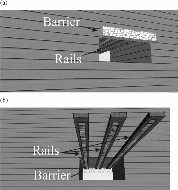
Schematic representation of a slag door hatch along with the barrier to prevent slag infiltration to the rails, a) inside view, b) outside view.
As seen in Fig. 4, the protective barrier covers the rails from the inside of EAF, which should prevent the slag to adhere to the rails and block the hatch when returning into the closed position. The length of the rails should be determined according to the EAF wall thickness to ensure complete removal of the hatch and thus a free slag-flow path. However; since at this point this is still a conceptual study, operation of the hatches and the mechanisms should be thoroughly tested in practice for its reliability. Whether the mechanism is inappropriate, another maintenance-free door design should be used.
In general, the doors are intended to function as a conventional slag door as well as to reduce energy losses due to excess slag. Furthermore, presented doors allow removal of the slag without tilting the EAF, reducing the mechanical stress and reducing the time needed to deslag the furnace in comparison to the conventional slag doors. Beside the aspects of energy savings and increased useful life of the EAFs (which are both challenging issues in the steel making field, especially with austenitic and duplex stainless steels), the proposed doors introduce an additional manipulated variable, which can be used to adjust the slag quality and thus leads to higher accuracy in element contents in austenitic and duplex stainless steel grades.
Below, a simulation based calculation is shown, comparing the energy consumption and tap-to-tap times of a conventional EAF and an EAF with the proposed slag doors.
The paper addresses the proposed innovation from two perspectives, i.e. from the energy and from the time point of view.
2.1. Energy SavingsIt is known that foamy slag has several beneficial effects on operation of the EAF, such as lower refractory erosion, lower arc noise and better energy transfer to bath. In order to take advantages of the slag, its height should be in the optimal range. Under certain unfavorable conditions in the furnace, it is likely to have a slag, which exceeds over the arcs and is thus out of its optimal range. The conditions, which occur due to excess slag, lead to increased energy losses due to contact between the slag and the furnace surfaces (water cooled panels, electrodes, roof etc.), refractory erosion, as well as unwanted electrical currents from the electrodes to the furnace surfaces. It is possible that excess slag causes energy losses to furnace surfaces exceeding the energy savings otherwise gained by the slag. Therefore, deslagging of the furnace in proper conditions can lead to increased energy efficiency of the EAF.
A typical EAF can schematically be divided into 11 main zones to quantify the role of excess slag on energy balance of each zone in contact with the slag. At this point, an assumption is made that each zone consists of identical materials and has the same temperature level; arcs - arc, solid scrap - sSc, liquid scrap - lSc, solid slag - sSl, liquid slag - lSl, gas - gas, electrodes - electrode, floor - floor, lower-wall or refractory brick - wall, upper-wall or water-cooled panels – water and roof - roof. In order to calculate the beneficial effects of the proposed solution, wall, water and electrode zones are further divided into smaller portions as follows. wall zone is divided into three areas; 1) first area ranges from the sill level to the slag level that covers the arcs, 2) second area ranges from the end of the first area to the arc attachment with the electrodes (when the arc is not immersed in the slag completely) or to the intersection of slag and gas (when the arc is immersed in the slag completely), 3) third area ranges either from the end of the second area (whether the second area exists) or from the end of the first area to the upper-wall cooled with water-cooled panels. According to the EAF conditions, it is possible that second and/or third area do not appear during the operation. Furthermore, water and electrode zones include two areas; 1) first area is surrounded by slag and 2) second area is surrounded by gas. According to the EAF conditions, it is possible that the first area does not appear during the operation.
During the EAF operation, variations in bath height, slag height and arc length can cause 7 different heat transfer paths inside the EAF as described by Table 1. Among them, excess slag leads to states F or G.
| A | LlSc+LsSc+LlSl+LsSl>Lwall, | Larc>LlSl+LsSl | Larc+LlSc+LsSc>Lwall |
| B | LlSc+LsSc+LlSl+LsSl<Lwall, | Larc>LlSl+LsSl | Larc+LlSc+LsSc<Lwall |
| C | LlSc+LsSc+LlSl+LsSl<Lwall, | Larc=LlSl+LsSl | Larc+LlSc+LsSc<Lwall |
| D | LlSc+LsSc+LlSl+LsSl>Lwall, | Larc=LlSl+LsSl | Larc+LlSc+LsSc>Lwall |
| E | LlSc+LsSc+LlSl+LsSl<Lwall, | Larc>LlSl+LsSl | Larc+LlSc+LsSc>Lwall |
| F | LlSc+LsSc+LlSl+LsSl<Lwall, | Larc<LlSl+LsSl | Larc+LlSc+LsSc<Lwall |
| G | LlSc+LsSc+LlSl+LsSl>Lwall, | Larc<LlSl+LsSl |
Where Lx is the height of the zone x.
When the furnace is properly deslagged, state F changes to state C and state G changes to state C or D. The later depends on combined arc and bath heights in comparison to the wall height. Furthermore, wall temperature is usually close to the slag temperature; therefore, significant temperature difference between wall and water zones exists. For this reason, removal of only a part of the excess slag touching the water zone can be rational. In such case, the heat-transfer path changes from state G to state F. As a result, eliminating the excess slag can be obtained in 4 cases.
Excess slag exchanges the energy with wall, water, roof and electrodes zones. Table 2 shows the main types of heat transfers between excess slag and the zones interacting with it. Generally, excess slag leads to increased heat losses through convection to wall, electrodes and water (except in the first case) zones, decreases the radiative view factor between the slag and the third part of the wall (in the first and the third case) and increases the view factor between the slag and the roof.
;%0A%09%09%09newWindow.document.open();%0A%09%09%09newWindow.document.write('<img src=%22./Graphics/57_1394_tbl_2.jpg%22>');%0A%09%09%09newWindow.document.close();%0A%09%09)
|
From the energy-saving point of view, slag doors should be opened if the MT obtained by Eq. (1), corresponding to the four abovementioned cases, is lower than the remaining tap-to-tap time and the predicted lifetime of the excess slag. MT represents an index to quantify when the excess slag imposes losses greater than the energy saved by the slag itself. The left side of Eq. (1) consists of two parts estimating convective and radiative losses caused by the excess slag. In order to obtain the radiative part, radiative losses have to be calculated for two cases, i.e. with or without the excess slag. In the following Equation, zone subscript shows the zone part as mentioned.
| (1) |
Removing the excess slag also affects the component masses. The amount of removed slag can be calculated using Eq. (2), which considers equal slag density along the slag height. The amount of components removed can be calculated using Eq. (3). Since the components can be distributed non-uniformly, Eq. (3) also considers a probability of certain compound being present in the excess slag.
| (2) |
| (3) |
The effect of the installed slag doors on time savings can be assessed in two aspects, i.e. improved EAF efficiency and required time to remove the slag. A desired deslagging time can be achieved by choosing a proper amount of doors and their dimensions.
The number of needed doors (n) can be estimated by Torricelli’s law, assuming proper effective viscosity of the slag, by Eq. (4):
| (4) |
The proposed modifications of the slag doors and the corresponding calculation algorithm have been added to the existing EAF model published previously.4,5,6) The model can predict variations in slag and bath heights, arc lengths and their effect on overall energy balance. Adding the described algorithm to the existent EAF model, a quantitative assessment of the proposed innovation can be made. It should be noted that calculated efficiency improvement shown in this study is optimistic, as the model considers the entire slag zone with the same temperature. In practice, it is expected to get lower improvements due to lower slag conductivity; however, the savings should still be measurable.
To quantify the effects of the proposed slag doors on overall EAF performance, two batches classified as the best operations are chosen. Figure 5 shows the comparison between the bath temperatures for both cases. The figures show three temperature simulations, i.e.: 1) the existent EAF operation (solid line); 2) operation of the EAF with the proposed slag doors and the same charging regime as in existent EAF operation (dashed line); and 3) operation of the EAF with the proposed slag doors and a new charging regime (dotted line), which allows charging of the second and third basket approximately 150 seconds earlier. The simulations assume that modified slag doors are opened as soon as the excess slag appears.

Comparison between bath temperatures for two batches. Solid line represents the simulated bath temperature of an EAF equipped with conventional slag doors. Dashed line represents the simulated bath temperature of an EAF equipped with the proposed slag doors, without changing the scrap charging regime. Dotted line represents the simulated bath temperature of an EAF equipped with the proposed slag doors and modified scrap charging regime.
In the cases shown, EAF power off is done at 2963 s of the first and 2882 s of the second heat. When comparing the bath temperatures, it can be seen that implementation of the proposed doors leads to approximately 9 K and 20 K bath temperature increment for the first and the second batch, when the charging trajectory is the same as in the existent EAF operation. The increment in temperature is equivalent to an overall EAF efficiency increase of 0.95% and 1.2% for the first and the second batch, respectively. Normally, the EAF is powered off when tapping temperature is reached. Using the proposed doors, a 9 K and a 20 K bath temperature increase show that tapping temperature will be achieved sooner, i.e. 55 seconds and 65 seconds for the first and the second batch, respectively. In other words, using the proposed doors as a manipulated variable without changing the conventional charging trajectory can reduce the power-on-time for approximately one minute. Moreover, due to roughly one minute shorter tap-to-tap times, an energy saving of approximately 4 kWh ton−1 and 5 kWh ton−1 for the first and the second batch is made, respectively.
When using a modified charging regime, meaning that the second and the third scrap baskets are charged 150 earlier, the temperature increment reaches 23 K and 21 K, respectively. Charging the EAF sooner causes electrical energy consumption decrease by 0.265% for the first and 1.52% for the second bath respectively. Furthermore, the simulations also show that due to increased bath temperatures and earlier charging, the tapping temperature will be achieved sooner, which leads to reduced tap-to-tap time for approximately 100–150 seconds.
The simulations show that operating the proposed slag doors together with the modified scrap charging regime leads to more efficient EAF operating than using just the doors and no charging modifications. However, it is not always possible to shorten the intervals between basket charging, due to various charging regimes and initial conditions. Such operation is shown in Fig. 6, which represents the simulated bath temperatures between the existent EAF operation and the operation of the EAF with the proposed doors and the same charging trajectory. In this situation the measured EAF power-off is performed at 3042 s and using the proposed doors the bath temperature at this point would be 17 K higher than existent, meaning that EAF power-off could be performed 80 s sooner. Therefore, the additional slag doors still allow shortening of the EAF power-on-time for approximately 80 seconds, but in this case cannot reduce the intervals between charging the baskets.

Comparison between bath temperatures. Solid line represents the simulated bath temperature of an EAF equipped with conventional slag doors. Dashed line represents the simulated bath temperature of an EAF equipped with the proposed slag doors without changing the scrap charging regime.
Whether the door size is assumed at 200 mm × 100 mm, considering the specific EAF, 9 door sets should be used to reach a deslagging time of 1 minute. A conventional EAF would need approximately 2 minutes to deslag the bath, which furthermore saves 0.5 kWh ton−1 of energy7) due to decrease of the power-off time for 1 minute. Furthermore, the allocated area for the presented doors (9 door sets) is approximately 3.5 times smaller than the conventional slag-door area.8) Since the presented study is still in its conceptual phase, all assumptions, calculations and simulations made in this paper should be thoroughly tested and validated in practice and the corresponding corrections should be made if necessary.
In the continuation of the EAF modelling, simulation and optimization research; the main focus will be on the development of a framework for optimal feeding trajectory determination, for both carbon and stainless steel production in the EAFs. The framework will rely on the effects of the proposed doors for optimal EAF operation, namely charging trajectory planning, energy use and time saving. Since finding the optimal scrap charging times is a complicated and a complex task, which is far too extensive to be added to this paper, the later mainly focuses on the idea of the proposed slag doors and their advantages when using the same charging trajectories, which are also not neglectable.
The paper presents a possible innovation to the EAF slag doors. A multi-hatch door sets mounted on the circumference of the EAF are proposed, and intended to remove the excess slag from the EAF or to completely deslag the furnace. Simulation results have shown that using the proposed solution, savings up to 5 kWh ton−1 of energy and approximately 1–2 minutes of tap-to-tap times can be made, due to removed excess slag and depending on the EAF operation (constant or modified charging trajectories). Furthermore, another 1 minute of tap-to-tap time could be saved when deslagging the EAF at tapping. Overall, using the proposed solution on a modern EAF would lead up to an estimated 1.5% decrease in total energy consumption and up to 3 minute decrease in tap-to-tap time.
The paper received funding from Sharif Research Energy Institute (SERI), project Simulation and control of an EAF. The support of SERI is kindly acknowledged.