Regular Article
Flow Field and Dross Behaviour in a Hot-Dip Round Coreless Galvanizing Bath
2017 Volume 57 Issue 9 Pages 1617-1624
Details
2017 Volume 57 Issue 9 Pages 1617-1624
This paper presents the results of fluid flow and dynamic behavior of dross in a hot-dip coreless galvanizing process by performing water modeling experiments and numerical simulations. NaCl aqueous solutions and plastic particles were employed as model fluid and top and bottom dross, respectively. The velocity distributions of the fluid were measured with the help of an Acoustic Doppler Velocimeter (ADV) for the strip speeds from 1.0 m/s to 2.7 m/s. The results from both water modeling experiments and numerical simulations showed that the flow in the bath is very complex and is determined by the strip speed, which is also a key factor for the distribution of top and bottom dross distribution in the bath. In the water modeling experiments applying the ADV at different strip speeds, some swirling flow which may drive the dross to the strip was observed on the surface of the bath, as well as inside the bath. And the swirling flow on the surface was disappeared when the strip speed was increased to 2.0 m/s. Consequently, high strip speed is favorable for the strip to avoid the dross adhering problem. In addition, bottom dross distribution was also investigated by using plastic particles. The results illustrate that bottom particles distribution is highly determined by the strip speed. Remarkably, more intensive flow driven by much higher strip speed (2.3 m/s) may roll up the bottom particles into the bath. This gives higher possibilities for the strip to cause surface quality problem.
Nowadays, the hot-dip galvanizing (HDG) productions are widely used for automotive and household appliance steel panel, electronics shell and extra corrosion resistance.1) Steel strips with different widths and various thicknesses are coated by rapid immersion in a Al–Zn liquid alloy bath operated at a speed of 1–3 m/s. Normally, it is very common that some dross are formed during this process due to chemical reactions in the Al–Zn liquid bath. Because of their different compositions, some dross floats up while others sink down in the bath. Since dross formation is a major production defect and not easy to overcome, decreasing the dross particles attached on the steel strip surface is a significant part to improve the surface quality. During the process, steel strip speed, width and bath configuration can influence the flow field of the Al–Zn liquid and alloy component, as well as the dross formation, distribution and coating quality of the steel strip.3)
Several previous investigations4,5,6,7,8,9,10,11,12,13,14,15,16,17,18) have attempted to understand the flow characteristics in the process of hot-dip rectangle galvanizing bath by performing numerical simulation and cold modeling experiment. Cold modeling experiment at a reduced scale is usually carried out to investigate the flow pattern of Al–Zn liquid in the HDG bath.4,5,6,7,8) To study dynamical features of flow, the Laser Doppler Velocimetry and Particle Image Velocimetry are usually employed. CaCO3 particles with a mean diameter of 0.001 m, and 5.0 mass% KCl aqueous solution were employed as tracers in a reduced scale of 1/10 continuous HDG plating bath by using a cold transparent model vessel.9,10,11) Li employed the black particles of acrylonitrile butadiene styrene as bottom dross to investigate the distribution and accumulations of bottom dross in a HDG bath.12) Although there are some limits of the program development, such as restrictions HDG bath with complex geometries and boundary conditions, numerical simulation studies can provide a fairly comprehensive information of flow, heat and mass transfer phenomena. As evidence, Al–Zn liquid flows inside an induction channel as well as flow inside a HDG bath were illustrated by using the commercial computational fluid dynamics software using a model of mass and momentum with the k-ε turbulence model.13,14,15,16)
However, most studies focus more on channel-type HDG process in rectangle bath while less on a coreless HDG process, which differs from that of the channel-type rectangle one. The round coreless bath for hot dip aluminum zinc alloy is advantage to the coating of aluminum zinc liquid with high aluminum content compared to rectangular bath for hop dip zinc coating. Because of the low density of aluminum, aluminum zinc alloy coating can reduce weight and provide better high temperature properties. Temperature distribution is more even in round coreless bath comparing with the conventional rectangular bath, especially in the four corners of the rectangular bath. The stirring effect of induction heating in round coreless bath has significant, accurate temperature control and strong mixing.
Till now, round coreless HDG process has been paid less attention on the flow field and dross distribution. Accordingly, for the development of efficient methods of removing dross, the work is aimed to elucidate flow phenomena and the dross movement in the HDG bath by applying physical and numerical simulations. The HDG bath consists of a sink roll, the strip and two stabilizing rolls. The schematic of apparatus for the coreless pot process is shown in Fig. 1.

A schematic diagram of the HDG pot.
According the similarity principle, geometry similarity, kinematic similarity and dynamic similarity can make sure the similarity of flow and other features between model and prototype. In the present study, the value of kinematic viscosities of water and Al–Zn liquid are close. So water modeling in the physical simulation can be applied to simulate the Al–Zn liquid flow. In addition, the Reynolds7) number and the Froude number were used to satisfy the dynamic similarity for designing the dimensions of water modeling. The Reynolds number (Re) and the Froude number (Fr) are defined as
| (1) |
| (2) |
The magnitude of the turbulent Reynolds number for the considered Al–Zn liquid and water were estimated in a magnitude of more than 105 and they are all in the second automatic simulation region.12) Reynolds number is in the second automatic simulation region in which flow state of fluid is turbulent flow. Fluid velocity distribution and flow regimes are not determined by the Reynolds number anymore. The Reynolds number of flow can be relaxed under total turbulent conditions for both model and prototype. The Reynolds number is not the key factor any more for the velocity distributions and flow regimes. Thus, Froude number between the model and the prototype was considered to be equivalent to make sure the similarity between model and prototype in this work.
According to the Froude similarity criterion,
| (3) |
| (4) |
Where, subscript m and p represent the physical and the prototype modeling, respectively.
On the basis of flow field similarity between the model and the prototype, appropriate particles selected as dross in the water modeling are further to satisfy dynamic similarity of dross movement such as flotation, dispersion, subsidence and transport of the dross. The Reynolds number, Shields number θ and Froude number for the particle were considered to investigate the motion of dross particles in the Al–Zn liquid flow. Shields number θ is chosen for guaranteeing similarity of scaling floating or sediment motion between model and prototype, which is defined as
| (5) |
Where, subscript inc and f represent the inclusion and the fluid modeling, respectively, D represents the diameter of inclusion.
As described previously, Reynolds number is in the second automatic simulation region in which flow state of fluid is turbulent flow. Thus Shields number and Froude number of the particles were adopted to ensure the similarity of dross motion between model and prototype.12) The density ratio between plastic particle and water is equal to that of the ratio between the oxidation density and the Al–Zn liquid alloy.12)
| (6) |
Where νf is the kinematic viscosity of a fluid.
Based on the above discussion, a 1/2.9 scale water modeling experiment was intended to perform the flow phenomena in a HDG bath. NaCl aqueous solutions and plastic particles were employed to simulate the Al–Zn liquid and the dross in the bath. As shown in Fig. 2, the physical modeling consists of a sink roll, a circle moving strip made by a rubber band with its width of 1.3 m, two stabilizing rolls and a DC (direct current) motor, which drives the strip to obtain different strip speeds. The inclination angle of entrance strip with the vertical plane is adjusted to 30 degree. The circle moving strip was motivated by a DC motor. Furthermore, in order to make sure the strip move smoothly to one side, the stabilizing rolls were installed at the top middle part of the bath. The operating parameters of the bath are listed in Table 1.
The experimental apparatus of the physical modeling.
| Parameters | Prototype | 1/2.9 Model |
|---|---|---|
| Zinc pot diameter, m | 2.5 | 1.2 |
| Zinc pot height, m | 2.1 | 0.7 |
| Liquid level height, m | 1.9 | 0.66 |
| Sink roll diameter, m | 0.8 | 0.276 |
| Stabilizing roll diameter, m | 0.2 | 0.069 |
| Strip width, m | 1.3 | 0.45 |
| Strip speed, m/s | 1.0, 1.3, 1.7, 2.0, 2.3, 2.7 | 0.58, 0.76, 0.98, 1.15, 1.35, 1.56 |
The effects of different strip speeds on the flow, as well as the dross distribution in the bath have been investigated in order to optimize conditions for suppressing the formation of dross particles. This approach is expected to provide an effective perspective for understanding the flow field and dross distribution in the round coreless HDG bath.
Experiment arguments for model and prototype are summarized in Table 1. Figure 3 presents lines and planes investigated in the physical and numerical studies. The Al–Zn liquid, NaCl aqueous solutions and simulation particles parameters are shown in Table 2.
The position of points, lines and planes (a) vertical plane (b) horizontal plane (c) side view.
| Parameters | Value |
|---|---|
| Al–Zn liquid viscosity, kg/(m·s) | 0.004 |
| Al–Zn liquid density, kg/m3 | 6600 |
| Plastic particles density, kg/m3 | 920, 1050 |
| Plastic particles mean diameter, m | 0.00015, .00003 |
| NaCl aqueous solutions, kg/m3 | 1050 |
Some fundamental characteristics and flow pattern, velocity profile were measured by using an Acoustic Doppler Velocimeter (ADV) to determine the turbulence of the flow in the bath. ADV measurements were applied for acquiring fluid velocities in a Cartesian coordinate system for three (xyz) directions. Normally, the measurement is performed after the experiment system runs for several minutes in order to get a steady flow, in turn, to get a stable data for velocity measurement. An example of velocity measurement can be seen in Fig. 4. The distance of two adjacent measure points is 0.01 m in the water modeling. The detailed position can be seen in Figs. 4(a) and 4(b). As shown in the figure, the measurements show very strong fluctuations in all three coordinates. The measured velocity for x, y and z are 1.94 cm/s, 0.95 cm/s and 1.76 cm/s, with their standard deviation of 2.0, 1.76 and 1.74, respectively. In the experiments, a transient velocity can be observed for each coordinate measurement. This transient velocity changes because of the flow fluctuation. Some acquired data would be removed as noise data during the measuring process. The record will be performed when the data on the screen are stable.

Three direction velocity measured in ADV.
In the development of the numerical model, the flow inside the bath is calculated as an incompressible fluid and is described by the continuity and momentum equations. The governing equations for fluid flow are represented as follows.
Continuity equation:
| (7) |
Momentum equation:
| (8) |
Considering the effect of Al–Zn liquid swirling with turbulence, the RNG k-ε turbulent model was adopted to resolve the effective viscosity.16,17)
Turbulence kinetic energy equation:
| (9) |
Turbulence kinetic energy dissipation rate equation:
| (10) |
Where
| (11) |
Effective viscosity:
| (12) |
Where Ω is a characteristic swirl number evaluated within ANSYS Fluent, and αs is a swirl constant that assumes different values depending on whether the flow is swirl-dominated or only mildly swirling. Model constants take on the constant value Cμ=0.0845, C1=1.42, C2=1.68, ak=aε=1.393.19)
3.2. Boundary Conditions and Numerical Solution ProcedureIn the current study, the following boundary conditions have been applied. For the free surface, the normal gradients of all the variables are set as zero.3) No slip conditions are applied to the solid bath walls in the bath. This implies all velocity components are zero at these walls. The standard wall function is used to incorporate the influence of turbulent flow for the near-wall treatment.
Al–Zn liquid is treated as incompressible viscous fluid. The physical properties of the Al–Zn liquid such as density and viscosity are constant values, which are shown in Table 2. Furthermore, the flow in the bath is turbulent with a turbulence intensity of 10%. Sink roll and stabilized rolls are set as movement walls with angular velocities. Horizontal and vertical velocities are applied to determine the steel strip velocity boundary conditions. The steel strip velocity and sink roll and stabilized rolls velocity can be found in Table 2.
The solutions of flowing equations carried out in the present work are based on the semi-implicit method for pressure-linked equations (SIMPLE). A three-dimensional computational domain is extracted and discretion into hexahedral cells with Gambit 2.4. The numerical simulation is performed by the software FLUENT 12.0. Numbers of hexahedron elements used in the fluid flow calculations are more than 1.3 million. The convergence is calculated as residuals less than 10–5.
A cross-sectional (Plane 1) for a flow chart is shown in Fig. 5. This result displays the flow pattern in an actual HDG line under the steel strip speed of 2.0 m/s in numerical simulation. In particular, the flow patterns are very complex in the “V” shape region enclosed with the steel strip, sink roll and stabilizing rolls which is installed to govern the steel strip. Multi-scales circulating flow exists inside of the “V-shape” region. The intensity of the flow within the region gradually increases with the increasing of the steel strip speed.

Flow pattern in the vertical plane 1.
Importantly, there are several circulations formed around the sink roll in the bath. These circulation flows are found to be decisive for the movement of the dross on top of the surface, bottom and inside of the bath. Consequently, the aim of this study is to investigate the effects of the strip speeds on the flow, as well as the dross behavior in the bath. The validity of the mode has been carried out using the water modeling in Ref.20). It can be seen that the numerical simulation results are in agreement with results in physical modeling.
To investigate the flow pattern reasonably, especially in the region near the strip, the velocity were measured by the ADV for plane 3, 4 and 5 in the water model, as presented in Figs. 6, 7 and 8, respectively. In general, fluid velocity increases when the steel strip speed is increased. According the comparison at three different levels, flow near the surface of the bath shows a more intensive fluctuation and higher velocity distributions.

Velocity distribution in the x-y plane acquired by ADV at the plane 3.
Velocity distribution in the x-y plane acquired by ADV at the plane 4.
Velocity distribution in the x-y plane acquired by ADV at the plane 5.
Specifically, vortex flow can be observed when the strip speed increased from 1.0 to 2.7 m/s at the plane 3. However, vortex can not be found when the strip speed is 1.0 and 1.3 m/s for the plane 4 and 5, and the flow patterns are significantly changed compared with the flow in position of plane 3. In addition, for the plane 4 and 5, as increasing the strip speed to 1.7 or 2.0 m/s, the vortex phenomena begin to appear and the intensity is increasing with increasing the strip speed. Overall, the comparison of different measured planes suggests that the flow pattern near the strip in the bath is depended on the strip speed as well as the level heights. It is very beneficial to understand the flow in the strip region, and then to study the particle behavior in the bath.
The effects of different strip speeds on the dross behavior at the top surface of the bath can be found from the profile of top dross distribution shown in Fig. 9. The flow shows a symmetrical pattern on the surface of the bath. And, the flow near the center position of the strip flows towards to the strip, which means, there are possibilities for the doss to adhere on the surface of the strip in this region if the flow is not appropriately formed. As can be seen from the Fig. 11, surface dross distribute uniformly on the surface of the bath when the strip speed is 1.0 m/s. When the strip speed is increased to 1.3 m/s, a large number of dross concentrate in the area which is near to the strip. The reason is that the flow with higher velocity drives the particle flow towards to the strip and velocity of flow near the strip increases as increasing the strip speed. This is also can be illustrated by the calculated velocity for line 1, as shown in Fig. 10. Reversed directions shown in the figure means that the flow near the strip flow towards to the strip while the flow far from the strip flows to the wall direction.
Particles distributed on the surface of the bath at different strip speeds.
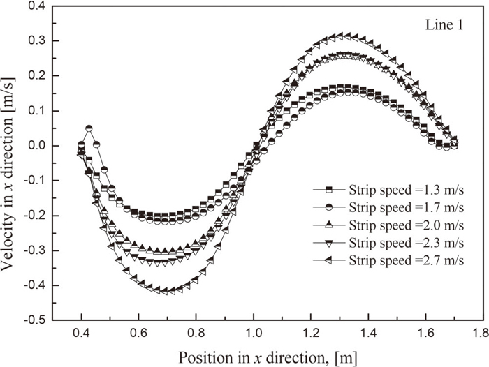
The calculated velocity in the numerical model for Line 1 with different strip speeds.

Bottom dross distribution with different strip speeds.
As the strip speed increases, the absolute value of velocity distributed increases because the movement of the surface becomes more intensive. Remarkably, as the strip speed increases to 2.0 m/s, the strip almost had no surface residue when the strip is pulled out. In other words, steel strip with high speed is favorable for dross removal from the strip when float dross exists in the bath. The observation from the experiments shows that this owes to the higher velocity of the flow which drives these particles to both side of the strip. In the industrial tests, some similar phenomena and tendency were also observed.
In addition, some vortexes, which make the dross easy to adhere on the strip, begin to appear near the strip when the strip speed over 1.3 m/s, However, when the strip speed increases to 2.0 m/s, the vortex moves away to both sides of the strip, which makes the dross difficult to adhere to the strip surface.
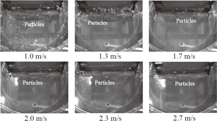
Figure 11 illustrates profiles of dross distribution resulted in the bottom of the bath when the steel strip speed is increased from 1.0 m/s to 2.7 m/s, together with the shadow outlines of doss distribution. For each investigation, the particles are distributed uniformly on the bottom wall before the experiment is performed. Once the motor is started, the particles will move following the liquid flow driven by the moving strip. As a result, this dross distribution in the bottom reflected partly the characteristics of the liquid flow in the bath.
When the strip speed is 1.0 m/s, a blank region, where the particles are removed by the flow, can be found at the bottom of the bath. This area is enlarged when the strip speed is increased to 1.3 and 1.7 m/s. The reason is that the flow intensity in this region is stronger compared with the region in other area at the bottom. Figure 12 shows the results of numerical model of velocity distribution in Plane 2. The vertical velocity towards the pot bottom is higher than other area of the plane, thus the particles in this bottom area are carried to somewhere else. It explains well how this blank region forms under current situation.

The velocity distribution for the Plane 2.
With the strip speed increasing, the motion of fluid in the bath is further intensified. The blank region becomes larger and larger when the strip speed increases to 2.7 m/s. This can be illustrated by the velocity distribution along the line 2. As can be seen from Fig. 13, the velocity in x = −0.5 m of the line 2 increases when the strip speed is increased although the peaks of the velocity for different strip speeds don’t show at the same position.

The calculated velocity in the numerical model for Line 2 with different strip speeds.
Also, some dross is rolled up by the vortex in the bath, which is not beneficial for the product quality. When the strip speed is 2.0 m/s, as can be seen from Fig. 11, blank region appears on the right side of the bath. Simultaneously, the dross in this region has also been gradually rolled up. A large part of these particles are driven and accumulated at the left side of the bath. Accordingly, this phenomena of dross distribution at bottom gives a clear information of the dross and is expected to introduce to practice to do an efficient work during the dross removal process.
Fluid flow and dross movement phenomena in a round coreless HDG bath were investigated by performing water modeling experiments and numerical simulations. Both experimental and numerical results have demonstrated some remarkable characteristics in the bath. The main conclusions are summarized as follows:
(1) The flow field of the fluid in the bath is very complicated, with forced convection derived from the strip movement. The flow pattern, as well as the dross distribution at the surface and the bottom of the bath, can be changed profoundly when the strip speed is increased.
(2) The particles on the surface are very easy to adhere on the strip because exist of the vortex formed near the strip when the strip speed is low, while they can be driven away to both sides of the roll when the strip speed is high. It is found that the strip almost had no surface residue when the strip is pulled out when the strip speed is higher than 2.0 m/s.
(3) Although high strip speed is beneficial for the strip to avoid surface adhering of dross, excessive strip speed (higher than 2.3 m/s in the experiment of this study) can roll up some bottom dross which may cause surface quality problem for the strip production. Consequently, the strip speed adopted for real practice should be considered for both top and bottom dross movement.
This work was supported by grants from the Key Laboratory Open Project Fund of Metallurgical Emission Reduction & Resources Recycling, Ministry of Education (KF17-06), Anhui University of Technology, Anhui University Provincial Natural Science Research Key Project (KJ2016A101), the National Natural Science Foundation of China (51004001).
Variables
Cd: Drag coefficient
D: Particle diameter (m)
Fd: Drag on a particle moving in liquid
Fr: Froude number
g: Acceleration due to gravity
L: Characteristic length
Re: Reynolds number
t: Time
u: Velocity
λ: Scale factor
ρ: Density
μ: Kinematic viscosity