Ironmaking
Changes in Microstructure and Chemical Composition of Deadman Coke of a 2800 m3 Industrial Blast Furnace
2018 年 58 巻 4 号 p. 667-676

詳細
2018 年 58 巻 4 号 p. 667-676
The paper examined the changes in microstructure and inorganic elements in their true mineral forms of the coke samples from various hearth locations using X-ray diffraction (XRD) and scanning electron microscopy-energy dispersive spectroscopy (SEM-EDS) after the blow out and cool down of a 2800 m3 industrial blast furnace. The results illustrate that all deadman coke samples from fines to lumps were confirmed to be highly graphitized. Furthermore, the deadman coke was filled up with the accumulated KAlSiO4 during its descent process and the blast furnace slag which consisted of Ca2MgSi2O7–Ca2Al2SiO7 system and Ca2ZnSi2O7 phases. Besides the slag phases, the iron was also observed in the deadman coke soaked in the iron layer. Those cause that the mass of the deadman coke is about 1.62–2.82 times larger than that of the feed coke under the same conditions. Thus it may make the deadman which was designed to float sit on the hearth bottom as the permeation of the slag and the liquid iron into the deadman coke was not taken into consideration during the design process. We concluded that the slag phase below the taphole level is primarily derived from the blast furnace slag. Moreover, the deadman coke carrying final slag may come in contact with the hearth bottom and react with ceramic pad or carbon brick with a sitting deadman, thereby it results in degrading the hearth lining. Meanwhile, the slag phases below the taphole level can provide the material for the formation of skull to protect the hearth lining.
Deadman is an almost stagnant zone in a blast furnace hearth.1,2) Deadman coke which is the only solid material remaining in a blast furnace hearth plays multiple roles by providing carburization source, permeable medium and mechanical support for the burden above the deadman.1) These important roles have a close relationship with the quality of molten iron, the hearth campaign life and the stable operation. Therefore, it is important to investigate the deadman coke behavior. Previous studies on deadman coke behavior of the hearth have mainly focused on its interaction with the blast furnace slag and liquid iron in the laboratory by using the feed coke without any other treatment.3,4) However, in the real blast furnace, the coke is subjected to the solution loss reaction, alkalis (Na, K) and the zinc vapors attack, high temperature, high pressure, and interaction with the liquid metal and slag phases, etc. before reaching the hearth level. Thus, some meaningful information about the hearth coke behavior of deadman may not be obtained in laboratory study. Due to the harsh environment, such as high temperature and multiphase, etc., it is often impossible to collect the coke samples from the zones below the tuyere level in an operating blast furnace. At present, the blast furnace dissection or overhaul is the only opportunity to obtain deadman coke from the blast furnace below the tuyere level. Previous research5,6,7,8,9) on the blast furnace hearth dissection focused primarily on investigating the relationships between the blast furnace operating conditions and the erosion profile. It gains a better understanding of the hearth. However, a limited number of papers have studied on the coke samples extracted from the deadman below the tuyere level.10,11,12) B.van der Velden et al.11) studied the microstructure of coke taken from different heights of the hearth after blowdown. They found that the slag partly drips into the coke pores at tuyere level, a large quantity of slag fills pores of coke at the liquid slag level, and liquid iron and slag permeate the coke pores at the liquid iron level, however, they did not study the mineralogy and graphitization of the deadman coke. Li et al.10) studied the graphitization of deadman coke and its interactions with slag with samples obtained from blast furnace center at the taphole level during its overhaul period. They found that hearth coke samples from fines to lumps were highly graphitized and slag phase filled up with all the macro coke pores, but they did not study the coke soaked in iron layer. Wang et al.12) studied the composition of coke extracted from the top of deadman to taphole level by proximate analysis during the medium maintenance. They found that slag impregnated coke, resulting in the decrease of fixed carbon and the increase of minerals in coke. They studied the minerals in oxide forms rather than the inorganic elements in their true mineral forms. These studies have deepened metallurgists’ understanding of deadman coke. However, the systematic and comprehensive studies on the inorganic elements in their true mineral forms, microstructure and coke carbon structure of deadman coke at different heights of blast furnace hearth especially the coke below taphole level are rare and insufficient.
In this paper, the microstructure of deadman coke and its composition as well as mineral phases were investigated in detail with samples obtained from different heights and different radius of the deadman of a 2800 m3 blast furnace during its overhaul period. Samples obtained from different positions can provide much meaningful information about the transformation of coke microstructure and organic compounds, and coke graphitization, which cannot be obtained from the laboratory research so as to give a deep insight into the understanding of the behavior and the characteristic of the large blast furnace deadman coke soaked in the slag layer and iron layer. The detailed study on deadman coke in this paper also contributes to lay the solid foundation for the improvement of the quality index of the large blast furnace coke and coal blending.
In the present study, the blast furnace from which the coke samples were obtained was a large size furnace of Ansteel with an inner volume of 2800 m3. The relevant parameters are listed in Table 1. Coke samples collected from the hearth deadman after blow out and cool down of the blast furnace. In this study, the horizontal positions of the collected coke samples are S1 at the center of blast furnace and S2, S3 at the subcenter of blast furnace (locating in the straight line of No. 4 and No. 18 tuyere and being 2850 mm away from the center). They are marked in the Fig. 1(a). The five vertical positions of coke samples locating at 1.8, 2.5, 3.3, 5.0 and larger than 5.0 m below the center level of the tuyere were labeled sequentially as DM1.8, DM2.5, DM3.3, DM5.0 and DM>5.0, as shown in Fig. 1(b).
| Parameter | Volume | Hearth diameter | Tuyere number | Depth of salamander | Blow in date | Blow out date | Tap hole number | Coke ratio | Coal ratio | Blast Temperature | Utilization coefficient | Hearth height | M10 | M40 | CSR | CRI |
|---|---|---|---|---|---|---|---|---|---|---|---|---|---|---|---|---|
| Unit | m3 | m | – | m | – | – | – | kg/t | kg/t | °C | t/(m3·d) | m | % | % | % | % |
| Value | 2800 | 11.6 | 30 | 2.4 | 2009-6-28 | 2016-9-20 | 3 | 347 | 160 | 1160 | 2.1 | 4.1 | 5.8 | 87.9 | 66 | 22 |

The schematic of the hearth coke sampling positions. (a) Horizontal positions; (b) Vertical positions. (Online version in color.)
Specimens were prepared by mounting the coke pieces in the rounded plastic pipes of 20–25 mm in diameter and about 10–20 mm in height which were filled with the epoxy resin. Then the specimens were ground and polished. The specimens were coated with carbon. The specimens were then examined with a Zeiss Evo18 Special Edition SEM-EDS for microstructure analysis, chemical analysis and mapping. Mineral phases and carbon structure in deadman coke and feed coke were identified using XRD analysis. The cokes were crushed to passing less than 74 μm and then were ashed by heating in air at 1088 K (815°C) to remove carbon similar to the previous studies.10,13) The samples for carbon structure identification were not treated by ashing process. XRD spectra were obtained using a Bruker diffractometer (D8 ADVANCE, Germany) as well as Cu (Kα) radiation. During this analysis, samples were scanned with 2θ in the range of 10 to 90 deg at a scan rate of 5 deg/minute. The chemical compositions of minerals in deadman coke were analyzed via X-ray fluorescence (XRF, Shimadzu XRF-1800, Japan).
To get a better understanding of the changes of deadman coke in the blast furnace smelting process, the feed coke was also studied. Figure 2 shows the microstructure of feed coke. Table 2 shows the EDS results of feed coke. Although the EDS analysis does not quantitatively measure the % composition of carbon, the relative abundances of carbon can be distinguished in the EDS results. Therefore, the carbon content is listed in the composition table to be analyzed qualitatively. The feed coke is mainly composed of the carbon (the black phases in Fig. 2), pores (the pits of different shapes in Fig. 2) and the inorganic compounds (white phases in Fig. 2). The distribution of the inorganic compounds and pores with the maximum size of up to 800 microns is non-uniform throughout the feed coke, which is shown in Fig. 2. The EDS analysis results show that the composition of the minerals is similar. Therefore, Table 2 only lists the ingredients of some representative points (the same below). The XRD pattern (Fig. 3) shows that the predominant phases of minerals in the feed coke are quartz and mullite, which is consistent with the observations in the previous works.14) Sulfur and nitrogen in the feed coke primarily exist in the form of organic compounds because the high content of sulfur, nitrogen and carbon, and few other elements are observed in some positions in the coke, as shown in P2. It is in accordance with the previous studies.15)

The microstructure of the feed coke (SEM image). (Online version in color.)
| Position | C | O | Al | Si | S | K | Ca | N | Sum |
|---|---|---|---|---|---|---|---|---|---|
| P1 | 32.97 | 29.54 | 18.63 | 18.50 | 0.00 | 0.37 | 0.00 | 0.00 | 100 |
| P2 | 95.07 | 0.00 | 0.73 | 0.87 | 1.50 | 0.00 | 0.00 | 1.84 | 100 |
| P3 | 46.73 | 27.17 | 12.90 | 13.20 | 0.00 | 0.00 | 0.00 | 0.00 | 100 |
| P4 | 18.17 | 33.20 | 24.80 | 22.36 | 0.00 | 0.00 | 1.47 | 0.00 | 100 |

The XRD spectra of the feed coke.
Table 3 shows the EDS results of deadman coke surface at different heights of the blast furnace center. The first row of Table 3 lists the final slag composition of Ansteel 2800 m3 blast furnace in the normal production. The maximum pore size of the deadman coke from DM1.8-S1 to DM>5.0-S1 is about 1300, 1500, 1500, 860 and 990 microns, respectively, which is larger than that of the feed coke (800 microns), as shown in Fig. 4. The main components of inorganic compounds in the deadman coke are Ca, Si, Al and Mg, which are quite similar to that of blast furnace final slag in the normal ironmaking process, as shown in Table 3. The XRD spectra of the minerals of the deadman cokes under the industrial blast furnace conditions are similar, which is notably different from the XRD spectra of the feed coke, as shown in Fig. 5. It is indicated that significant changes of the minerals in the deadman coke have taken place. The minerals in deadman coke were mainly made up of akermanite (Ca2MgSi2O7) and gehlenite (Ca2Al2SiO7) system which are the most common minerals in the blast furnace slag,16) hardystonite (Ca2ZnSi2O7) and kaliophilite (KAlSiO4). Besides, magnetite (Fe2O3) was observed in the XRD spectra of DM>5.0. The absence of quartz (SiO2) and mullite (Al6Si2O13) which are the predominant phases of minerals in the feed coke is also confirmed in the diffraction pattern of deadman cokes, as shown in Fig. 5. The compositions of minerals in deadman coke are very close to that of final slag, as shown in Table 4. The content of potassium in deadman coke minerals is higher than that in final slag. So the final slag is not the main source of potassium in deadman coke minerals. Kaliophilite, which is the main phase of potassium in deadman coke minerals, occurs in all deadman cokes possibly due to the interaction between potassium vapor and the mullite in the ash of the feed coke during its descent process.17) The viscosity of slag increases with the decrease of temperature. It is difficult for slag to penetrate into the open pores of the deadman coke under the conditions of low slag temperature, low blast pressure, and low internal-external pressure difference of the deadman coke pores during the tapping of overhaul period. Therefore, the inorganic compounds in the deadman coke is not the ash remaining in the feed coke, but the blast furnace final slag penetrated through coke open pores and the accumulated kaliophilite during its normal production. Magnetite (Fe2O3) in the remnant mineral matter of DM>5.0 was formed by the reoxidation of iron in the ashing process, as shown in Fig. 5. Besides penetration of slag, the molten iron infiltrates the pores of deadman coke, as shown in Fig. 4(e), which is in agreement with the XRD results (Fig. 5 DM>5.0).
| Area | C | Al | Si | Ca | Mg | Fe | O | S | K | Mn | Sum |
|---|---|---|---|---|---|---|---|---|---|---|---|
| Final slag | 0.00 | 8.85 | 16.05 | 29.47 | 3.96 | 0.00 | 40.64 | 1.03 | 0.00 | 0.00 | 100 |
| P1 | 43.15 | 11.60 | 4.69 | 14.56 | 2.08 | 0.00 | 23.92 | 0.00 | 0.00 | 0.00 | 100 |
| P2 | 93.73 | 0.00 | 0.85 | 1.90 | 0.00 | 0.94 | 2.58 | 0.00 | 0.00 | 0.00 | 100 |
| P3 | 98.84 | 0.00 | 0.00 | 0.60 | 0.00 | 0.00 | 0.00 | 0.56 | 0.00 | 0.00 | 100 |
| P4 | 0.00 | 44.8 | 0.00 | 0.00 | 18.36 | 0.00 | 36.85 | 0.00 | 0.00 | 0.00 | 100 |
| P5 | 79.78 | 2.15 | 3.13 | 2.22 | 0.58 | 0.00 | 8.10 | 0.34 | 2.53 | 1.17 | 100 |
| P6 | 29.68 | 25.47 | 0.00 | 0.00 | 11.09 | 0.00 | 33.3 | 0.00 | 0.00 | 0.45 | 100 |
| P7 | 19.06 | 13.91 | 11.30 | 32.38 | 2.01 | 0.00 | 21.33 | 0.00 | 0.00 | 0.00 | 100 |
| P8 | 18.27 | 9.02 | 14.09 | 28.79 | 3.59 | 0.00 | 25.33 | 0.91 | 0.00 | 0.00 | 100 |
| P9 | 17.84 | 8.26 | 14.30 | 31.45 | 3.31 | 0.00 | 24.03 | 0.81 | 0.00 | 0.00 | 100 |
| P10 | 87.91 | 1.36 | 1.89 | 3.87 | 0.48 | 0.00 | 3.92 | 0.57 | 0.00 | 0.00 | 100 |
| P11 | 2.82 | 10.16 | 11.95 | 31.89 | 3.87 | 4.03 | 31.44 | 0.96 | 1.11 | 1.77 | 100 |
| P12 | 0.00 | 0.00 | 0.00 | 0.00 | 0.00 | 100 | 0.00 | 0.00 | 0.00 | 0.00 | 100 |

The microstructure of coke in the center of the furnace at different levels. (a) DM1.8-S1 (DM1.8 stands for vertical position and S1 stands for horizontal position, similarly hereinafter); (b) DM2.5-S1; (c) DM3.3-S1; (d) DM5.0-S1; (e) DM>5.0-S1. (Online version in color.)
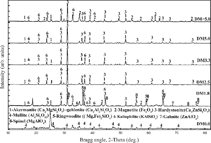
The XRD spectra of mineral matter of the deadman coke at different positions. (DM0.0-Feed coke).
| Items | CaO | SiO2 | Al2O3 | MgO | K2O | ZnO |
|---|---|---|---|---|---|---|
| Slag in coke | 36.78 | 33.70 | 19.72 | 6.57 | 3.23 | 0.01 |
| Final slag | 39.80 | 32.80 | 16.19 | 7.33 | 0.38 | 0.03 |
| Position | C | Mg | Al | Si | Zn | Na | O | N | Sum |
|---|---|---|---|---|---|---|---|---|---|
| P1 | 77.43 | 4.72 | 11.57 | 0.17 | 0.00 | 0.00 | 6.11 | 0.00 | 100 |
| P2 | 72.11 | 0.00 | 4.61 | 0.00 | 10.06 | 0.74 | 12.48 | 0.00 | 100 |
| P3 | 21.61 | 0.00 | 0.00 | 0.00 | 70.03 | 0.00 | 8.36 | 0.00 | 100 |
| P4 | 98.31 | 0.00 | 0.89 | 0.00 | 0.00 | 0.00 | 0.00 | 0.80 | 100 |
| Area | C | O | Mg | Al | Si | S | K | Ca | Mn | Fe | P | Sum |
|---|---|---|---|---|---|---|---|---|---|---|---|---|
| P5 | 0.00 | 33.98 | 4.86 | 10.89 | 14.81 | 0.00 | 0.00 | 35.46 | 0.00 | 0.00 | 0.00 | 100 |
| P6 | 0.00 | 32.01 | 2.53 | 15.13 | 13.37 | 0.00 | 0.00 | 36.95 | 0.00 | 0.00 | 0.00 | 100 |
| P7 | 85.51 | 4.89 | 0.75 | 1.57 | 2.07 | 0.00 | 0.95 | 4.26 | 0.00 | 0.00 | 0.00 | 100 |
| P8 | 92.61 | 2.24 | 0.45 | 0.91 | 1.17 | 0.00 | 0.59 | 2.03 | 0.00 | 0.00 | 0.00 | 100 |
| P9 | 11.33 | 24.17 | 4.16 | 9.51 | 14.43 | 2.21 | 0.00 | 34.18 | 0.00 | 0.00 | 0.00 | 100 |
| P10 | 7.84 | 0.00 | 0.00 | 0.00 | 0.00 | 0.00 | 0.00 | 0.00 | 1.73 | 89.91 | 0.51 | 100 |
| P11 | 2.76 | 31.99 | 2.00 | 18.71 | 13.43 | 0.00 | 0.00 | 31.11 | 0.00 | 0.00 | 0.00 | 100 |
Compared with the feed coke, the walls of deadman coke pores become thinner, which is attributed to several factors such as the high degree of gasification due to prolonged stay, the adsorption of recirculating alkalis and zinc as well as the interaction with penetrated slag and iron. Some coke pores that are initially closed or not interconnected turn open or connect with each other after the consumption of coke walls, as demonstrated in Fig. 4. The number of the open pores and the open porosity decrease remarkably while the amount of penetrated slag and liquid iron increases significantly, as shown in Figs. 4(c)–4(e). The impregnated area of the slag and liquid iron accounts for about 24%, 30% and 21% of the cross section of DM3.3-S1, DM5.0-S1 and DM>5.0-S1, respectively. Some potassium in deadman coke can be inserted into the carbon layer existing in the form of graphite intercalation compounds as the potassium content of P5 in the Fig. 4(b) is obviously higher than that of the corresponding components in the final slag, which is in agreement with previous studies.17) Magnesium-aluminate Spinel (P4 and P6) was observed in deadman coke.
3.3. The Microstructure and the Composition Analysis of the Coke Inside in the Subcenter of the FurnaceThis paper only shows the results of S2 because the results of S3 are similar to that of S2. Mg–Al (P1) and Zn–Al (P2) compounds are observed in DM1.8-S2, which are in accordance with XRD spectra of mineral matters of DM1.8 (Fig. 5). Zinc oxide (P3) also occurs in DM1.8-S2. It is indicated that the zinc vapor penetrates into the coke through the open pores and is absorbed by the coke. It may lead to the generation and expansion of micro-pore and the increase of the pore diameter, causing serious damage to coke structure and decreasing the strength of the coke.18) Ca, Si, Al and Mg that are the major components of blast furnace final slag in the normal production are the main constituent of minerals in deadman coke. Meanwhile, compared with the feed coke, the content of Ca, S and Mg in the inorganic compounds of deadman coke increase significantly. Iron is also observed in deadman coke (Fig. 6(e)), indicating that the DM>5.0 soaked in the iron layer. The coexistence of the iron and slag in DM>5.0 shows that the slag in deadman coke of the iron layer derives from the coke passing through the slag layer into the molten iron layer. The above analysis shows that the slag and hot metal can seep into the interior of the coke, which is in agreement with the XRD results (Fig. 5). The coke at the bottom of deadman is dotted with white matters (slag and iron) with the naked eye (Fig. 6(f)), further explaining that the blast furnace slag and liquid iron can impregnate the deadman coke and the slag phases in coke of the deadman bottom can come into contact with the ceramic pad with a sitting deadman.

The microstructure of coke in the subcenter of the furnace at different level. (a) DM1.8-S2; (b) DM2.5-S2; (c) DM3.3-S2; (d) DM5.0-S2; (e) DM>5.0-S2; (f) Actual photograph of the deadman coke in the salamander. (Online version in color.)
In combination with the composition of inorganic compounds in the surface of deadman coke, it is indicated that slag and liquid iron can not only penetrate into the coke surface, but also the interior of the coke, reducing the coke porosity and the number of open pores enormously. The maximum pore size can reach about 1700, 1600, 1600 and 1800 microns in the order of DM1.8-S2, DM2.5-S2, DM3.3-S2, DM5.0-S2, DM>5.0-S2 which is much bigger than the maximum pore size (800 microns) of the feed coke. The area of the slag and iron impregnated accounts for about 12%, 27%, 28% and 44% of the cross section of coke at 2.5, 3.3, 5.0 and larger than 5.0 meters below the centerline of the tuyere, respectively.
The ash yield of deadman cokes at different locations is presented in Fig. 7. The ash yield of deadman coke increases greatly from tuyere level to hearth bottom, which is much higher than the ash yield (15%) in the feed coke with the exception of DM1.8. The average ash yield in the hearth coke below taphole level is about 45%. The ash yield of DM>5.0 is up to 70%, which is higher than that in the real blast furnace due to the oxidation of iron during ashing treatment. High ash yield in the deadman coke can be attributed to the penetration of slag and metal droplets. The mechanism of penetration of slag and hot metal into the coke and its related factors need further study.
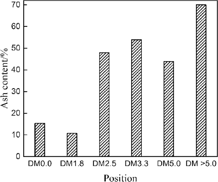
The ash yield of deadman cokes at different locations. (DM0.0: feed coke).
Figure 8 shows EDS maps showing the distribution of Ca, Si, Al, Mg, S, K, O and Fe of the coke at the bottom of the deadman. The inorganic compounds in the deadman coke are made up of CaO–SiO2–MgO–Al2O3 with small amounts of sulfur (Fig. 8(a)), which is similar to the typical composition of standard blast furnace slag. Also, a certain amount of iron is observed in the coke pores. Besides the sulfur in mineral form, other sulfur spreads in the carbon-based matrix of coke in the form of stable organic sulfur (Fig. 8(c)), indicating that the organic sulfur in feed coke can only be reduced with the solution loss reaction, combustion and carbon dissolution reaction in the process of blast furnace production. The potassium was observed not only in the carbon-based matrix of the coke but also in the minerals (Fig. 8(b)). It showed that the potassium vapour can not only be inserted into the carbon layer to form the graphite intercalation compounds, but also react with the aluminosilicate compounds in the feed coke to form KAlSiO4 accumulated in the pores during its descent process which is in accordance with the XRD results (Fig. 5).
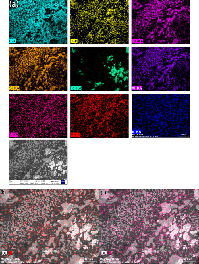
EDS maps showing the distribution of Ca, Si, Al, Mg, S, K, O and Fe of the coke at the bottom of the deadman. (a) The distribution of all elements; (b) The distribution of K; (c) The distribution of S. (Online version in color.)
Figure 9 shows the XRD pattern of deadman coke fines (<3 mm), deadman coke lump and feed coke. From the classical Scherrer equation, we can know that a sharp and narrow 002 carbon peak indicates high ordering of the carbon structure.19) The 002 carbon peak of the deadman coke lumps and feed coke are clearly asymmetric and can be resolved into three peaks,20) as shown in Fig. 9(c). It is proposed20) that three peaks are as follows: peak 1, the broad low intensity peak, is attributed to disordered carbon in the coke; peak 2 is observed at low scattering angle and corresponds to the peak due to heat treatment and peak 3, at the highest scattering angle, is due to the graphite formed by the catalytic graphitization. The broad and diffuse 002 carbon peak of the feed coke provides the low value of the stack height of carbon crystallites and indicates poor ordering of carbon structure, as shown in Fig. 9. It is clearly shown from Fig. 9 that, in the coke lumps, the heat-treatment and catalytic graphitization have an important influence on the coke graphitization. The peak 3 of the DM1.8 and DM>5.0 is obvious, which may be related to the iron and magnetite in the coke lump (Fig. 5) as they can catalyse coke graphitization.20) Whether blast furnace slag plays a catalytic role in the graphitization of deadman coke needs further study.

The XRD spectra of deadman cokes at different heights. (L-lump; F-fines). (Online version in color.)
The 002 carbon peak of the deadman coke fines is relatively symmetric and thus is not resolved into three peaks. Table 7 presents the results of XRD studies of the deadman coke samples. Table 7 and Fig. 9 show that there is an obvious shift of the carbon peak positions of the deadman cokes towards the right side compared with the feed coke, indicating that graphite crystals of the deadman coke possess a lower interlayer spacing d002 than the feed coke. The d002 value of all deadman coke fines is estimated to be about 0.339 nm which is very close to the interlayer spacing of pure graphite (0.338 nm10)). The crystallite height of the carbons of deadman coke fines is larger and increases from 24.31 to 44.35 nm from DM1.8-F to DM>5.0-F, which is about 5–10 times the value of the crystallite height of the feed coke. The average crystallite height of carbons of deadman coke lumps ranges from over 11 nm for DM1.8-L to about 16 nm for DM3.3-L which is much higher than that of the cokes (3–7 nm19)) at tuyere level and the feed coke (4.0 nm). It may relate to the contribution of prolonged hot metal contact,20) prolonged final slag contact and high temperature treatments19) on improving the ordering of carbon structure of coke. The average interlayer spacing d002 of deadman coke carbons ranges from 0.3386 nm to 0.3498 nm which is less than that of the feed coke (0.3607 nm). The 002 carbon peak width of the deadman coke fines is the smallest compared to that of the deadman coke lumps and the feed coke and the 002 carbon peak width increases in the order: deadman coke fines, deadman coke lumps, feed coke, as shown in Fig. 9. This implies that the most ordered carbon structure occurs in deadman coke fines, followed by deadman coke lumps and the feed coke. Gupta19) and Li10) found that the graphitization of coke in the high temperature zone starts from the coke surface and the graphitization process leads to the formation of coke fines. The previous studies21,22) proposed that the carbon in highly ordered coke would be easier to dissociate and this leads to higher dissolution rates. Therefore, the deadman coke graphitization can promote carburization; On the other hand, it can lead to the formation of coke fines.
| Samples | 2-Theta (°) | Interlayer spacing d002 (nm) | Full width at half maximum (°) | Crystallite height lc (nm) | ||||||||
|---|---|---|---|---|---|---|---|---|---|---|---|---|
| Peak1 | Peak2 | Peak3 | Peak1 | Peak2 | Peak3 | Peak1 | Peak2 | Peak3 | Peak1 | Peak2 | Peak3 | |
| DM0.0 | 23.510 | 24.710 | 25.890 | 0.3781 | 0.3600 | 0.3439 | 2.38 | 1.57 | 1.75 | 3.37 | 5.13 | 4.61 |
| DM1.8-L | 24.720 | 25.570 | 26.080 | 0.3599 | 0.3481 | 0.3414 | 1.54 | 0.63 | 0.52 | 5.23 | 12.79 | 15.52 |
| DM2.5-L | 25.270 | 25.650 | 26.080 | 0.3522 | 0.3470 | 0.3414 | 0.60 | 0.53 | 0.54 | 13.43 | 15.21 | 14.94 |
| DM3.3-L | 25.456 | 25.810 | 26.200 | 0.3496 | 0.3449 | 0.3399 | 0.52 | 0.50 | 0.50 | 15.50 | 16.13 | 16.14 |
| DM5.0-L | 25.300 | 25.670 | 26.090 | 0.3517 | 0.3468 | 0.3413 | 0.73 | 0.52 | 0.53 | 11.03 | 15.50 | 15.22 |
| DM>5.0-L | 25.340 | 25.810 | 26.300 | 0.3512 | 0.3449 | 0.3386 | 0.66 | 0.60 | 0.50 | 12.21 | 13.44 | 16.14 |
| DM1.8-F | 26.299 | 0.3386 | 0.33 | 24.31 | ||||||||
| DM2.5-F | 26.280 | 0.3388 | 0.25 | 31.90 | ||||||||
| DM3.3-F | 26.261 | 0.3391 | 0.34 | 23.46 | ||||||||
| DM5.0-F | 26.299 | 0.3386 | 0.23 | 34.79 | ||||||||
| DM>5.0-F | 26.300 | 0.3386 | 0.18 | 44.35 | ||||||||
The above analysis shows that the final slag and liquid iron can penetrate into not only the coke surface, but also the interior of coke. The R index is proposed to evaluate the influence of the infiltrated iron and slag on the mass of the deadman coke, as shown in the following equation
| (1) |
The mass of deadman coke by penetration of slag and iron at most of the hearth locations is about 1.62–2.82 times larger than that of the feed coke under the same conditions (Table 8). This shows a substantial increase of deadman coke mass when the coke reaches to the slag layer and the iron layer. The penetration by slag and liquid iron of the deadman coke increases its gravity, which may make the deadman designed to float sit on hearth bottom. When the deadman is sitting on the bottom, the hot metal circulation is faster and the wall shear stress is larger near the bottom corners leading to serious erosion.23,24) The previous models of the deadman force analysis24,25) need further improvement to evaluate the deadman status more accurately during the normal ironmaking process because they did not consider the effects of the permeation of the slag and liquid iron on the deadman gravity. The state of the deadman is also important to determinate the reasonable salamander depth during the design process.
| Position | DM0.0 | DM1.8 | DM2.5 | DM3.3 | DM5.0 | DM>5.0 |
|---|---|---|---|---|---|---|
| mbf (g) | 4.00 | 4.00 | 4.00 | 4.00 | 4.00 | 4.00 |
| maf (g) | 0.61 | 0.43 | 1.92 | 2.16 | 1.76 | 2.80 |
| R | 1.00 | 0.95 | 1.62 | 1.84 | 1.51 | 2.82 |
The existence of slag phase below the taphole level has been controverted for many years.26,27) It is difficult for blast furnace slag to dip below the taphole level directly because the considerable variation of density exists between the hot metal and liquid slag. However, blast furnace slag can enter the salamander indirectly. The composition and phase analysis of minerals in the deadman coke indicates that the slag phase existed below the taphole level is mainly originated from the blast furnace final slag and the accumulated kaliophilite during its descent process. The blast furnace slag penetrates the deadman coke through the coke open pores in the slag layer. The deadman coke subjected to the penetration of slag in the slag layer moves to the salamander and then the blast furnace slag that penetrated into the pores of the coke is also brought into the salamander.
3.7. The Effect of Mineral Phases in Deadman Coke and Coke Graphitization on Hearth ErosionCarbon bricks will be eroded inevitably if they are contacted with the liquid slag directly.28,29) Also, ceramic pad can react with liquid slag and liquid slag can permeate into the ceramic pad with deadman sitting on bottom, leading to the destruction of ceramic pad.28,29,30,31) The blast furnace slag and kaliophilite in deadman coke below the taphole level are exposed to the hot metal due to carbon dissolution of coke into liquid metal. Highly graphitized deadman coke fines covering the surface of coke lumps contribute to carburization, improving carburized rate and increasing the amount of slag phase in iron layer. Also, the deadman coke with high ordering of carbon structure may generate more fines and then decrease the deadman permeability. If the hearth is in an inactive status, some high melting point slag phase such as kaliophilite (KAlSiO4, 1800°C32)), gahnite (ZnAl2O4, 1950°C33)) and spinel (MgAl2O4, 2135°C34)) in the iron layer may exist in a solid form. During the process of floating, the solid slag may adhere to the surface of coke, form a film of slag, and reduce the rate of coke carburization. When the slag film on the coke surface reaches a certain extent, the gaps between deadman cokes will be blocked. It enhances peripheral flow and decreases the contacting area between the liquid iron and coke carbon, resulting in the decrease of carbon dissolution of coke and the increase of carbon dissolution of the carbon brick exposed to molten iron. Deadman cokes carrying final blast furnace slag may come in contact with the hearth bottom and react with ceramic pad with a sitting deadman and carbon bricks of hearth sidewall located below the taphole level, degrading the refractories and bringing negative influence on the blast furnace campaign life. On the other hand, the blast furnace slag existing in salamander provides the material for the formation of the skull (a layer of solidified iron and slag, and graphite) on the hot surface of the refractory linings below the taphole level, protecting blast furnace linings from erosion. Some researchers27) found that the protective layers sampled 1 m below the taphole level contain the slag phases whose major crystalline phase is magnesium melilite (Ca2MgSi2O7). Our results show that the magnesium melilite is one of the main phases in the deadman coke below the taphole level. Therefore, blast furnace slag in the deadman coke may be the main source of the slag phase in protective layers rather than the coke ash. In short, the slag existed in the salamander and the changes of coke carbon structure present both positive and negative effects on the blast furnace campaign life. The effects of the blast furnace final slag on the hearth bottom and hearth sidewall refractory require detailed study, as it may be one of the important factors of hearth refractory damage below taphole level.
This paper studied the microstructure, mineral phases and chemical composition of samples of coke collected from the hearth deadman after blow out and cool down of a 2800 m3 blast furnace. The following results are presented.
(1) Compared with the feed coke, the wall of the deadman coke pores becomes thinner and the pore size becomes larger. Some coke pores that are initially closed turn open after the consumption of the coke walls and connect with each other.
(2) The paper concludes that the blast furnace slag and molten iron infiltrate the pores of deadman coke. The minerals in deadman coke were mainly made up of akermanite (Ca2MgSi2O7) and gehlenite (Ca2Al2SiO7) system, hardystonite (Ca2ZnSi2O7) and kaliophilite (KAlSiO4).
(3) The average interlayer spacing of deadman coke carbons varies from 0.3386 nm to 0.3498 nm, which is less than that of feed coke (0.3607 nm). The crystallite height of the carbons of deadman coke ranges from about 11 to 44 nm while that of feed coke is 4.4 nm. The 002 carbon peak width of deadman coke fines is the smallest compared to that of deadman coke lumps and feed coke. The most ordered carbon structure occurs in deadman coke fines, followed by deadman coke lumps and feed coke. High graphitization of deadman coke presents both positive (contributing to carburization) and negative (resulting in the coke fine formation) effects.
(4) The ash yield of the deadman coke increases greatly from the tuyere level to the hearth bottom. The average ash yield in hearth coke below taphole level is about 45%. The mass of deadman coke with penetration of slag and iron at most of the hearth locations is about 1.62–2.82 times larger than that of the feed coke under the same conditions. The slag and iron penetration of the deadman coke increases its gravity, which may make the deadman designed to float sit on hearth bottom.
(5) The slag phase below the taphole level is primarily derived from the blast furnace slag. The deadman coke carrying final slag may come in contact with the hearth bottom and react with ceramic pad or carbon bricks with a sitting deadman, thereby it leads to the degrading of the refractory and the lower blast furnace campaign life. Besides, the slag phases below the taphole level can also provide the material for the formation of the skull to protect the hearth lining.
(6) The quality of the coke is not only related to the state of the deadman, but also has a close relationship with the protected layer and the erosion of the hot surface of the refractory below the taphole level.
This project was supported by the Anyang Iron and Steel and the National Natural Science Foundation of China (No. 61333002; No. 61571040).