Transformations and Microstructures
Nanobainite Layer Prepared by Laser Hardening Combined with Isothermal Transformation
2018 年 58 巻 5 号 p. 952-957

詳細
2018 年 58 巻 5 号 p. 952-957
Nanobainite layer was prepared by laser hardening combined with isothermal transformation (LHCIT) at 250°C, which between Ms and Md temperature. The microstructures of the nanobainite layer were analyzed by X-ray Diffraction (XRD) and transmission electron microscope (TEM). The nanohardness of the nanobainite layer were measured by the nano-mechanical tester. The results show that the residual stress value of the laser hardening layer is 319.15 ± 21.05 MPa, and the shear band such as stacking fault bundle, nano-twin and ε-martensite can be formed by the stress in austenite during LHCIT. The highest nano-indentation hardness of the nanobainite layer is 8.81 GPa and the average nanohardness of the nanobainite layer is evidently increased from 6.65 GPa to 7.76 GPa. The reduced hardness is bimodal in the laser hardening layer, and it is demonstrate that the high hardness of the nanobainite layer can be obtained by the formation of the shear band.
Nanostructured materials with a special atomic structure, which contain extremely large fraction of grain boundaries, have been developed rapidly.1,2,3,4) As one of the bulk nanostructured materials, the nanobainite with excellent strength and ductility has been considered to be obtained by an uncomplicated manufacturing route.5,6,7) During the nanobainite transformation, the dislocations can be formed in and around the bainitic ferrite coupled with its growth, and the excess carbon is reluctantly partitioned from bainitic ferrite.8) In the previous literatures, M. Zhang et al.9) found that the bainite with high hardness (592–628 HV) can be obtained in supercooled austenite of medium-carbon high-silicon steel during the deformation and following austempering at 250°C. A. J. Kaijalainen et al.10) investigated the rolling of bainite steel in the non-recrystallization temperature regime of austenite which is an effective way to improve the strength, impact and fracture toughness, of the bainite steel.
Recent experimental studies have showed that a viable means of quenching and partitioning (Q&P) can generate a modified microstructures containing metastable residual austenite in various steels.11,12) Treated by Q&P process, the residual austenite can be modified by transformation-induced plasticity (TRIP) during deformation and contributes to formability and energy absorption, therefore, a good combination of strength and ductility of the steel can be achieved.13,14)
It is worth mentioning that the improved mechanical properties of the steels owing to TRIP effect are mainly because the ε-martensite and α’-martensite may be transformed from the austenite.15,16)
Laser surface modification technology, which has the advantage of intense energy flux and small heat affected zone, is also effectively used for surface strengthening of complex shaped metals. However, the relatively large stress is induced unavoidably during the laser surface treatment.17) It is considered that the stress can be relieved by heat treatment, but temper softening in the same process. Focus on this issue, improving the fracture resistance without deteriorating the strength/ductility can be realized by the acquisition of shear band, such as stacking faults, nano-twin, ε-martensite. As a result, bainitic surface modified layers were fabricated by using laser hardening combined with isothermal transformation (LHCIT) method in the present study.
The steel used in this work is Fe–0.54C–2.53Si–1.82Mn–1.08Cr–0.45Ni–0.32Mo (wt.%). The Ms temperature of the steel was measured by Gleeble-3800 thermal mechanical simulator, which is 230°C. The steel was homogenised at 1200°C for 3 h, and the homogenized specimens were austenitized at 1000°C for 15 min and then isothermally transformed at 250°C for 24 h to obtain a bainite microstructure, which is defined as Specimen A. Then the specimens were machined to the dimension of 40 × 20 × 10 mm3 and cleaned in ethyl alcohol. Laser remelted by CO2 laser device in an Argon protection box. The laser power (P) was 1.8 kW, and the laser spot diameter (D) was Φ3 mm during LHCIT. The experiment was conducted on a heating platform, which was used to preheat the substrate. The preheating temperature was same as the following isothermal transformation temperature, which was detected by thermocouple thermometer. The steel was laser remelted in an Argon protection box and followed isothermal transformation at 250°C for 24 h, which is defined as Specimen B.
2.2. Microstructure ObservationThe microstructures of the nanobainite layer were observed by filed emission scanning electron microscopy (FESEM, Hitachi S4800), and the microstructures and corresponding selected area diffraction (SAD) pattern were observed by transmission electron microscopy (TEM, JEM-2010). The phase constitution was determined by X-ray diffractometer (XRD, D/max-2500/PC) with Cu Kα radiation at 40 kV and 20 mA. During the test, 40°<2θ<120° with a step size of 0.02° was set and the dwell time was 10 s. The XRD results were analyzed by Rietveld method in combination with the Materials Analysis Using Diffraction (Maud) software from three or more XRD scan data for each steel. The analysis were performed imposing a body-centred tetragonal lattice
Nano-mechanical tester (CPX-NHT2) equipped with a diamond Berkovich tip was conducted for hardness determination using the load of 5 mN and dwell time of 10 s during the test. Moreover, the distribution of nanohardness and the reduced hardness were performed by 225 indentations (a regular array of 15 × 15 indentations covering a 70 × 70 μm2 area).
The atomic plane spacing in the metallic crystal structure can be changed by the elastic strains when the steel is under stress, which can be measured by X-ray diffraction. The X-ray residual stress analyzer (Proto iXRD) was used to detect the residual stress perpendicular and parallel to the laser scanning directions followed by EN 15305-2008 standard test method. Residual stress was performed in a regular array of 5 × 4 testing points covering a 16 × 12 mm2 area of the hardening layers center.
Figure 1 illustrates the XRD patterns of Specimen A and Specimen B. As shown in Fig. 1(a), the phase structure is primarily composed of α–Fe and γ–Fe, which represent the bainitic ferrite (BF) and retained austenite (RA) respectively. Figures 1(b) and 1(c) shows the elaborate observation of the XRD patterns, which also exhibit that the peaks of ε–1010, ε–0002 and ε–1120 are slightly visible in Specimen B. The peaks of HCP were weak as a relatively fewer fraction of ε-martensite phase in Specimen B, but compared to Specimen A, it is obvious that the ε-martensite phase exists in Specimen B. Talonen et al.18) and Kundu et al.19) has found that the α’-martensite phase nucleates at the intersections of shear bands, and the growth of α’-martensite occurs by the repeated nucleation of new embryos and coalescence. The low diffraction peak intensity of ε-martensite maybe because of the growth of α’-martensite.

XRD patterns of the steel: a) XRD patterns for the specimens under different treatments; b) detailed of XRD patterns from 42° to 47°; c) detailed of XRD patterns from 77° to 84°.
Figure 2 represents the microstructures of the specimens with different treatments. As shown in Fig. 2(a), the microstructure of Specimen A consists of BF with darker long and slender morphology, and RA with film and blocky morphology. During the bainite transformation, the carbon partitions from the BF into the RA to make the carbon supersaturated in the RA.20) The bainite transformation stop when the carbon content in RA reaches T0 temperature,6) and the BF with straightness grain boundary can be formed. Meanwhile, the metastable blocky RA can also be observed in Fig. 2(a) clearly. While, Fig. 2(b) shows an obvious ultra-fine-grain structure in Specimen B after LHCIT and the submicron blocks of RA is difficult to be identified inside the nanobainite.
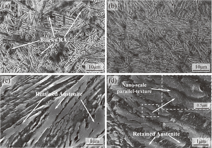
SEM morphologies of microstructure: a) Specimen A; b) Specimen B and Enlarged SEM morphologies of microstructure; c) Specimen A; d) Specimen B.
Compared with Figs. 2(c) and 2(d), the enlarged SEM morphology of the specimens illustrates that the nano-twin is generated greatly during LHCIT, because large amount of nano-scale parallel-texture can be found to be embedded in the film RA regions in Fig. 2(d), which, in contrast, is difficulty to be seen in Fig. 2(c).
3.3. TEM AnalysisFigure 3 gives the TEM image of the stacking fault bundles, nano-twin and ε-martensite of Specimen B. Figure 3(a) shows the bright field image of the dense stacking fault bundles of Specimen B. The dark field image in Fig. 3(b) and SAD pattern illustrate that the electron diffraction spots are elongated where the stacking fault bundles are indexed in bcc crystals. The stacking fault is overlapped on (111) planes, and the shear band can be formed. If the overlapping stacking fault is successive, then a planar defect is referred to form nano-twin.1) The twin can be formed by the slip of Shockley partials on successive slip planes.21) A normal fcc stacking sequence ABCABCABCABC, and the slip of first partial b produces an intrinsic stacking fault, which is identical to removing a layer of B (ABCABCABCABC) atoms. The stacking sequence is ABCABCACABCA. The slip of the second b partial on an adjacent slip plane, which is identical to removing a layer of A (ABCABCACABCA) atoms. The stacking sequence is ABCABCACBCAB. The stacking fault convert into a two-layer twin nucleus (ABCABCACBCAB).

TEM morphology stacking fault bundles: a) bright field image; b) dark field images.
Figure 4(a) shows the bright field image of the nano-twin of Specimen B, which is consistent with its SAD pattern and the dark field image in Figs. 4(b) and 4(c). As illustrated in Fig. 4(a), the dislocation debris are evidently distributed in one side of the nano-twin. The nano-twin grow easily once it is nucleated.22) While, when the dislocation motion is hidered, the dislocation can also be absorbed by the twin boundaries to sustain a large plastic deformation, which is different from the high-angle grain boundaries effects during the deformation process.23)

TEM morphology of the austenite nano-twin in Specimen B: a) bright field image; b) dark field image; c) dark field image.
The TEM micrographs of the ε-martensite and its corresponding SAD in Specimen B are presented in Fig. 5. Figure 5(a) is the bright field image, and Fig. 5(b) is SAD pattern from [0111]ε zone axe. According to the SAD pattern, the crystal parameters of the ε-martensite with hcp structure are a=0.39 nm and c=0.24 nm. It is consistent with the XRD analysis and the crystal structure of ε-martensite, which is shown in Fig. 1. The ε-martensite has been reported to be almost ideally plastic, which is frequently observed after deformation above the Ms temperature, and overlapping stacking fault is formed regularly on every second {111}γ plane.18) Y. T. Tsai et al.24) investigated the microstructure evolution of nanostructured bainite under deformation by Hopkinson pressure bar experiment, and the ε-martensite was observed in thin film austenite. The orientation relationship between austenite and ε-martensite was determined to be [110]γ//[2110]ε, and (111)γ very close to (0001)ε. It was reported that the deformation mechanisms changed with increasing stacking fault energy (SFE) from dislocation glide and ε-martensite formation (SFE~10 mJ m−2), to dislocation glide and mechanical twinning (SFE~19 mJ m−2) to only dislocation glide (SFE~80 mJ m−2).25,26) The defects in structure and high strain values can be induced by laser treatment.27) Therefore, it is possible that the ε-martensite can be formed by LHCIT. While, it is difficult to thermally induce ε-martensite by cooling without LHCIT during the transformation of austenite.

TEM morphology of ε-martensite in Specimen B: a) bright field image; b) dark field image.
The residual stress comparison of the specimens are detected. The residual stress value of the Specimen A is −15.26 ± 11.31 MPa, and the bainite transformation is displacive in nature so that the Specimen A retains a small number of compressive stress. The tensile stress is appeared in Specimen B after LHCIT, and the residual stress value of the specimen is 319.15 ± 21.05 MPa. Compared to the Specimen A, the stress induced by LHCIT makes the stacking fault bundles, nano-twin and ε-martensite are formed in Specimen B.
3.5. Nano-mechanics PropertiesFigure 6 shows the typical cross-sectional micromorphology and nanohardness gradient of the Specimen B. From Fig. 6(a), the micromorphology of nanobainite layer consists of equiax crystal, dendritic crystal and heat affected zone (HAZ), respectively. The microstructure of nanobainite layer is compaction without metallurgical defects. Nano-indentation hardness gradient of the Specimen B on the polished cross-sectional specimen are plotted against the distance below the surface in Fig. 6(b). Compared to the matrix of Specimen B, the average nanohardness of the laser hardening layer is evidently increased from 6.65 GPa to 7.76 GPa, and the nano-indentation hardness of the nanobainite layer is reached to 8.81 GPa. With the increased distance from the surface, the hardness at HAZ of LHCIT layer is slightly declined, but still higher than that of the matrix bainite. It is mentioning that there are relatively low hardness area in the nanobainite layer. With the high magnification morphology of indentation (the insert graph in Fig. 6(b)), it can be observed that the indentation position is just in the dendritic segregation area. The segregation of alloying elements, such as manganese, silicon and chromium on the solidification of alloys lead to the increase of the austenite stability, and then the bainite transformation is suppressed.

Results of cross-sectional micromorphology and nanohardness gradient of the Specimen B: a) cross-sectional micromorphology; b) nanohardness gradient.
The nanohardness distributions of the specimens over a 70 × 70 μm2 square area are shown in Figs. 7(a) and 7(b), which indicate that the hardness of the nanobainite layer is improved obviously after LHCIT.
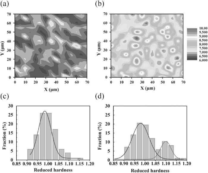
Results of nanohardness values distribution: a) Specimen A; b) Specimen B; and reduced hardness values: c) Specimen A; d) Specimen B.
It can be seen that there are large difference in the hardness distribution range between Specimen A and Specimen B. Based on the comparison of the results after normalization, the hard points can be highlighted by calculating the reduced hardness.
The reduced hardness (Hri) can be determined as:
| (1) |
The reduced hardness values of the two specimens are shown in Figs. 7(c) and 7(d). By fitting the relationships with Gauss functions, the reduced hardness distributions of both specimens are located between 0.92 and 1.20. There is a single peak in the Specimen A, which represents that the reduced hardness is 0.98. While, the reduced hardness is bimodal in Specimen B, in which the peaks of the reduced hardness locate at 0.97 and 1.09. It can be inferred that the existence of the shear band is the main factor for the bimodal. The above results demonstrate that the high hardness of the nanobainite layer can be obtained by the formation of the shear band.
It is obvious that the shear band is expected to be induced by the thermal stress in bainitic surface modified layers during LHCIT, and the mechanical properties of the surface modified layers are expected to be improved by the formed shear band.
The above results demonstrate that the high performance of LHCIT layers can be obtained by the formation of the shear band, which are associated with the accumulated motion of stacking faults. The shear band forms due to the overlapping of stacking faults on {111}γ planes,26) and the overlapping of the stacking faults can be classified into: (1) overlapping on irregularly pattern, the stacking fault bundle forms; (2) overlapping on successive {111}γ plane, nano-twin forms; (3) overlapping regularly on every second {111}γ plane, perfect ε-martensite phases with the hexagonal close-packed (hcp) crystal structure forms.
Whenever the shear band appeared, the stress-induced martensite can be transformed by strain inducing.21) It is known that the formation of stress-induced martensite is related to the overlapping of stacking faults on {111}γ close-packed atom planes.28,29) As the treated temperature is above Ms and below Md, the martensite transformation can be induced by stress-assisted.11)
The Md temperature is the major critical factor to present the deformation-induced martensite transformation, which can be calculated by Eq. (2):30,31)
| (2) |
From Eq. (2), the Md temperature of the steel can be calculated, which is 267°C. It can be concluded that the transformation should be induced via stress-assisted nucleation during cooling. When the stress exists under the yield limit of parent austenite between Ms and Md temperatures, the transformation is dominated by stress-induced nucleation on new nucleation sites.
(1) Nanobainite layer of the mid-carbon high-silicon steel can be obtained by LHCIT and the TEM results demonstrate that the stacking fault, nano-twin and ε-martensite in the nanobainite layer are induced by the stress in austenite during LHCIT.
(2) The high hardness of nanobainite layer is obtained by LHCIT. The hardness of the modified layer treated by LHCIT is enhanced from 6.65 GPa to 7.76 GPa.
(3) The reduced hardness is bimodal in the laser hardening layer, and it is demonstrate that the high hardness of the nanobainite layer can be obtained by the formation of the shear band.
This work was supported by the National Natural Science Foundations (Grant Nos. 51471148, 51375425 and 51705447), P. R. China.