Ironmaking
Preparation of High-Carbon Metallic Briquette for Blast Furnace Application
2019 年 59 巻 1 号 p. 22-30

詳細
2019 年 59 巻 1 号 p. 22-30
Developments in blast furnace (BF) ironmaking have long focused on low-coke operation. In this study, high-carbon metallic briquettes (HCMB) were prepared using ultrafine iron oxide powders and coal fines for BF application. The preparation conditions were optimized, and the binding mechanism of the briquette was analyzed. The gasification behavior of the optimally prepared HCMB was investigated under conditions simulating the in-furnace environment of the BF, and its application in BF was evaluated through numerical simulations. The results showed that the optimal preparation condition was mhematite/mcoal = 2.0. The optimally prepared HCMB had a carbon content of 25.6 wt%, cold strength (CS) of 1300 N/briquette, and crushing strength after reaction (CSR) of 2500 N/briquette. The high strength of the briquette was attributed to the iron network binding. The threshold temperature and activation energy of the briquette gasification in the blast furnace were 973 K and 166 kJ/mol, respectively. Simulation results on the HCMB application in a BF of 2500 m3 indicated that mixing HCMB of 5% into the ore burden could save approximately 12.5 kg of coke for producing one ton hot metal from the ore.
Blast furnace (BF) ironmaking is a major hot metal manufacturing process, and it will remain so in the foreseeable future. As coke is the most important raw material for this process and occupies a considerable portion of the hot metal cost, developments in the BF sector have long focused on low-coke operation technologies. Nowadays, owing to a demand in reducing environmental pollution in coke production and a decrease in the coking coal supply,1,2,3,4,5,6) the development of these technologies becomes even more urgent.
Coke performs the following three functions in BF ironmaking:7) a thermal function, as fuel providing the heat required for endothermic reactions and for melting of the iron and slag; a chemical function, as a reductant providing reducing gases for iron oxide reduction; and a mechanical function, as a permeable grid allowing the passage of liquids and gases in the furnace, especially in the lower part of the BF. The low-coke operation of BF can be achieved when certain functions of the coke, e.g., as fuel, reductant, and carburizing agent, are covered by supplying other cheap carbonaceous materials (oil, gas, biomass, and non-coking coals). Most of these low-coke operation technologies concentrate on reducing coke consumption below the cohesive zone (CZ). The major development in this aspect is pulverized coal injection (PCI) technology, by which non-coking coal is substituted for a part of the coke in the raceway. By applying catalyzed coal gasification,8) oxygen enrichment in the blast,9) and a high-temperature blast,10) PCI rate nowadays reaches approximately 200 kg PC per ton hot metal.11,12) Further increasing PCI rate faces several difficulties. For example, a very high PCI rate would significantly affect the bed permeability and the gas flow pattern in the lower part of the furnace.13) Some newly developed technologies have targeted reducing coke consumption in the BF region with temperatures of 1073–1473 K. In this region, approximately 10% of the coke is consumed by the carbon solution-loss reaction.14) Some researchers proposed to suppress coke gasification by mixing passivators into the coke; however, the effect of passivators is not evident.15) Some researchers proposed using highly reactive ferro-coke to protect coke from gasification; however, in the raw material for preparing the qualified ferro-coke, the coking coal still occupies a considerable portion.16,17) Therefore, reducing coke consumption in BF ironmaking merits further study.
Metallic briquette (direct reduced iron or hot briquette iron) has partially replaced traditional BF iron-bearing burdens in some countries.18,19) The metallic briquette is usually produced from iron-ore and carbon agglomerate and usually has a carbon content of 2.0 to 5.0 wt%.20,21) Mixing the metallic briquette in the ore burden is mainly for increasing BF productivity. It is thought that the function of the metallic briquette in the BF could be extended; if the metallic briquette could be prepared with a high carbon content without deteriorating its strength, carbon in the metallic briquette could also be gasified where the carbon solution-loss reaction of coke occurs. This, in turn, would alter the BF gas composition and might have some positive effects on the low-coke BF operation.
In this study, the high-carbon metallic briquette (HCMB) was prepared by roasting a cold-bonded iron-oxide-coal agglomerate. The preparation conditions of the HCMB were optimized with respect to its carbon content, cold strength (CS), and crushing strength after reaction (CSR). Thereafter, the gasification behavior of the optimally prepared HCMB was investigated under conditions simulating the in-furnace enviroment of the BF, and its microstructure evolution during gasification was examined. At the same time, its effect on coke saving in BF was evaulated through simulation studies.
Non-coking coal and pure iron oxide were used as raw materials. The non-coking coal powders were for PCI operation, supplied by Jianbang Iron & Steel company (Shanxi, China), and its properties are given in Table 1. The Fe2O3 powders (analytical reagent) were purchased from Sinopharm Chemical Reagent Co. (Shanghai, China). The average grain sizes of Fe2O3 powders and of coal powders were 2.35 and 55.85 μm, respectively.
| Proximate Analysis/ad, wt% | Ultimate Analysis/daf, wt% | Ash Analysis/wt% | |||||||||||
|---|---|---|---|---|---|---|---|---|---|---|---|---|---|
| VM | FC | Ash | M | C | H | O | N | S | SiO2 | Al2O3 | Fe2O3 | CaO | MgO |
| 20.03 | 69.97 | 9.09 | 0.91 | 88.60 | 3.50 | 5.93 | 1.67 | 0.30 | 40.95 | 39.04 | 9.66 | 4.51 | 0.84 |
VM-Volatile Matter; FC-Fixed Carbon; M-Moisture; ad- air dry basis; daf-dry and ash free.
The iron oxide and the coal powders were thoroughly mixed with the addition of 10% distilled water and 2% organic binder (cellulose). In the mixture, the mass ratio of iron oxide to coal (mhematite/mcoal) was predetermined. These moistened fines were pressed into iron-oxide-coal agglomerates using a die under a pressure of 30 MPa. After being air dried for 24 hours, followed by drying at 383 K for 2 hours, the dried agglomerates were subjected to roasting in an electric furnace under N2 atmosphere. During the roasting process, the furnace was heated from room temperature to 1273 K at a rate of 5 K/min; after being maintained at 1273 K for 30 min, the furnace was allowed to cool down naturally. The prepared briquette had a cylindrical shape (diameter = 15 mm and height = 15 mm). The mass of each briquette was approximately 6.0 g. In total, seven HCMB samples were prepared, and their preparation conditions are listed in Table 2. The appearance of the prepared HCMB is shown in Fig. 1.
| Sample | A | B | C | D | E | F | G |
|---|---|---|---|---|---|---|---|
| (mhematite/mcoal)/– | 0 | 0.5 | 1.0 | 1.5 | 2.0 | 2.5 | 3.0 |
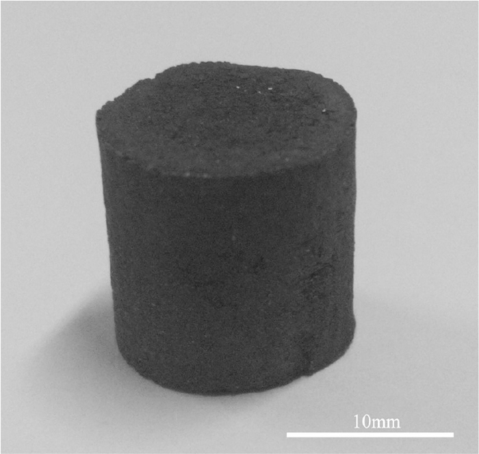
Appearance of the HCMB sample.
CS tests for the HCMB samples were conducted using a MJDW-10B electronic universal testing machine (Maijie Co, Jinan, China). The load speed of the jig was set at 20 mm/min. The arithmetic mean of five tests done on each sample was calculated as the final value.
The CSR test for the HCMB samples was conducted using the same methodology as was used for the CS test. The reaction conditions for the CSR test were determined using a reference for the in-furnace environment of the BF at 1373 K. Under these conditions, both iron ore reduction and coke gasification could proceed actively.7) The briquette was subjected to reacting under an atmosphere of 80 vol%CO and 20 vol%CO2 and a temperature of 1373 K in an alumina tube reactor (diameter = 45 mm) for an hour. The total gas flow rate for the reactor was kept at 2000 mL/min (standard temperature and pressure (STP)).
2.3. Gasification TestsGasification tests for the HCMB sample were conducted using a custom-built thermalgravimetric device. A schematic diagram of the device is shown in Fig. 2. The device includes a gas supply system, an electronic scale with an accuracy of ±0.001 g, and a temperature-controlled furnace with an accuracy of ±2 K. The furnace was heated using MoSi2 elements, producing a 50 mm hot zone in the reaction tube (diameter = 55 mm). The sample holder was made of a heat-resistant alloy wire (Fe–Cr–Al). The furnace was first preheated to the desired temperature and stabilized for 30 min under N2. One briquette was loaded into the sample holder, preheated at 773 K for 5 min in the upper part of the reaction tube, and then introduced into the hot zone. At this time, N2 was replaced with a CO–CO2–N2 or a CO–CO2 gas mixture, and the mass of the briquette was measured using the electronic scale and recorded using a computer every 2 seconds. After a predetermined time, the briquette was withdrawn from the hot zone and cooled under N2. During the test, the total gas flow rate in the reaction tube was maintained at 3000 mL/min (STP).

Schematic diagram of the experimental setup.
Selected HCMB samples were analyzed and characterized using the following techniques. Carbon content was measured using a CS-2800 infrared carbon sulfur analyzer (NCS Co., China). Phase identification was conducted through X-ray diffraction (XRD) using a DMAX-RB X-ray diffractometer (Rigaku Co., Japan). Microstructure observation was conducted through scanning electron microscopy (SEM) using a Quanta-250 scanning electron microscope (FEI Co., US).
The carbon contents of the seven HCMB samples are given in Table 3. The samples exhibited a wide carbon content range. Sample A, which was prepared using only the coal fines, had a carbon content of 91.0 wt%, and sample G, which was prepared under mhematite/mcoal = 3.0, had a carbon content of 9.8 wt%.
| Sample | A | B | C | D | E | F | G |
|---|---|---|---|---|---|---|---|
| Carbon content/wt% | 91.0 | 65.5 | 45.7 | 33.4 | 25.6 | 14.9 | 9.8 |
The results of the CS tests are shown in Fig. 3. It can be observed that the CS of samples A, F, and G were greater than 2000 N/briquette, the CS of samples B and E were close to 1300 N/briquette, and the CS of samples C and D were less than 1000 N/briquette.

CS of the prepared samples.
After reacting under the simulated BF’s in-furnace environment of 1373 K for an hour, the carbon gasification ratios of the prepared samples are listed in Table 4. The results of the CSR tests are displayed in Fig. 4. As can be seen in Fig. 4, samples A, B, C, and D showed a strength lower than 1000 N/briquette; however, samples E, F, and G showed a strength greater than 2500 N/briquette.
| Sample | A | B | C | D | E | F | G |
|---|---|---|---|---|---|---|---|
| Gasifcation ratio/% | 32.0 | 35.0 | 34.0 | 43.0 | 72.0 | 93.0 | 94.0 |

CSR of the prepared samples.
In BF operation, both CS and CSR of normal ore-carbon composites are usually required to be greater than 1200 N/briquette.22) To realize a partial substitution of the coke in BF, it is preferable for the carbon in the HCMB to be as high as possible, in addition to its base requirement in CS and CSR. In BF ironmaking, the hot metal is carbon saturated and has a carbon content of 4 wt%. Therefore, the available carbon for gasification in sample E is 22.6 wt% after removing the required carbon for carburization of its own iron; the available carbon contents for gasification in samples F and G are 11.5 and 6.2 wt% respectively. It is clear that the carbon for gasification in sample E is much higher than that in samples F and G. With respect to carbon content, CS, and CSR, sample E was considered to be adequate for the BF application. The optimal condition for preparing HCMB was thus mhematite/mcoal = 2.0.
The CS of the HCMB is closely related to its microstructure. The XRD pattern of sample E, shown in Fig. 5, indicated that the iron oxide powders in the briquette had been completely reduced by the reaction given by Eq. (1) in the slow roasting process.
| (1) |

XRD pattern of sample E.
Figure 6 shows the microstructures of all prepared samples. Samples A and B exhibited a dense structure, and the iron grains in sample B (typical diameter: 2 μm) were sparsely distributed among the much larger carbon particles. These findings indicated that the high CS of samples A and B was due to the binding of the plastic phase generated through coal pyrolysis. Sample C exhibited a loose structure of pores and fissures. In sample C, short iron fibers (typical length: 10 μm and typical diameter: 2 μm) were formed, but these short iron fibers remained sparsely distributed among the carbon particles. The microstructure of sample D was similar to that of sample C, except that the size of iron fibers grew larger. These findings indicated that the iron oxide reduction had ruined the plastic phase, resulting in a low CS in samples C and D. The microstructure of sample E showed that the short iron fibers were densely distributed and most were hosted on the carbon particles within a distance close to be connected. The microstructure of samples F and G clearly showed the interconnection of iron fibers. The high CS of sample E could then be attributed to the connection of iron fibers rather than the binding of the plastic phase. The iron fiber distribution over a larger area of sample E outlined an iron network in the briquette (Fig. 7), which indicated that the high CS of sample E was due to the primary iron network acting as a binder.

SEM images of the prepared samples.
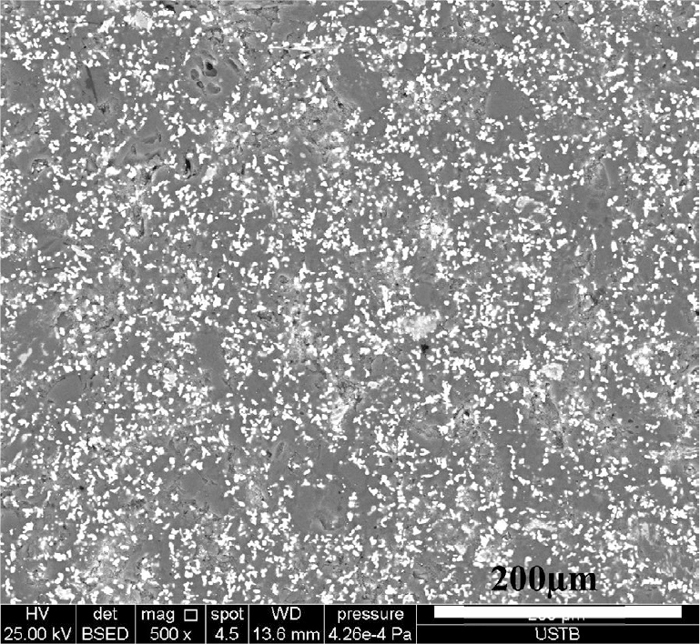
SEM image of sample E.
After the reaction under the conditions simulating the BF region of 1373 K, the CSR of samples A, B, C, and D were very low as the plastic phase had been completely destroyed in the reaction. However, the CSR of samples E, F, and G remained high as their strength depended on the binding of the iron network. Figure 8 shows the microstructure of sample E after the reaction. Long iron fibers (typical diameter: 15 μm) were formed, and some long iron fibers could entwine carbon particles as large as 50 μm (Fig. 8(a)). The iron distribution over a larger area of sample E clearly presented an iron network (Fig. 8(b)), indicating that the iron network in the briquette had been reinforced. Therefore, the CSR of samples E, F, and G became even higher than their respective CS.
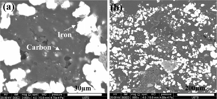
SEM images of sample E after reaction.
The threshold temperature is the initial temperature at which an observable mass loss of the HCMB begins to occur in BF. In order to design experiments for simulating the in-furnace environment of the BF, it is appropriate to know the variation in temperature and gas composition profiles in the BF. BF gas is composed of CO, CO2, N2, H2, and H2O. Fractions of H2 and H2O are relatively small, so only CO, CO2, and N2 were included for simulating the BF gas. Six scenarios were designed according to the relationship between (PCO2/(PCO2 + PCO)) and temperature in the modern BF,7) and they are listed in Table 5.
| Scenario | Temperature/K | CO2/vol% | CO/vol% | N2/vol% |
|---|---|---|---|---|
| I | 773 | 25 | 25 | 50 |
| II | 873 | 25 | 25 | 50 |
| III | 973 | 25 | 25 | 50 |
| IV | 1073 | 20 | 30 | 50 |
| V | 1173 | 15 | 35 | 50 |
| VI | 1273 | 10 | 40 | 50 |
The results of the briquette mass change with time under the different scenarios are given in Fig. 9. The mass change in Fig. 9 was calculated using Eq. (2).
| (2) |

Mass changes of sample E under conditions simulating the in-furnace enviroment of the BF.
Under scenarios I and II, the briquette exhibited a successive mass gain; however, the degree of mass gain was insignificant by the end of the test. Under scenario III, the briquette mass remained almost unchanged. Under scenarios IV, V, and VI, the briquette presented a successive mass loss. The final amount of mass loss became observable under scenarios V and VI. Under the scenarios given in Table 4, two reactions, namely, iron oxidation given by Eq. (3) and carbon gasification given by Eq. (4), could take place. The mass gain was clearly attributed to the iron oxidation reaction and the mass loss carbon gasification reaction.
| (3) |
| (4) |
The equilibrium constants of the iron oxidation reaction (K3) and the carbon gasification reaction (K4) are given in Eqs. (5) and (6), respectively;23)
| (5) |
| (6) |
From Eqs. (5) and (6), it is known that both iron oxidation and carbon gasification could take place under scenarios I–V, and only carbon gasification could take place under scenario VI. Therefore, combining the results from Fig. 9, it is known that, in the BF region with a temperature below 973 K, the dominant reaction in the briquette is iron oxidation, and in the BF region with temperature above 973 K, it is carbon gasification. Ignoring iron oxidation, the threshold temperature of the briquette is approximately 973 K. The threshold temperature of the conventional coke is approximately 1123 K in the BF.14) Therefore, compared to the conventional coke, the threshold temperature of sample E is 150 K lower.
3.3. Gasification Kinetics of HCMBThe gasification kinetics of the optimally prepared HCMB (sample E) were examined at temperatures ranging from 1273 to 1373 K and under an atmosphere of 80 vol%CO and 20 vol%CO2. The variations of carbon conversion over time for different temperatures are depicted in Fig. 10. Figure 10 indicates that, under 1373 K, carbon conversion becomes saturated after 5400 seconds. During gasification, the iron fibers in the briquette agglomerated together, forming an iron crust. When gasification reached a high level, the iron crust became dense and caused a resistance to gas diffusion, and further gasification of the carbon became very difficult. Under the investigated conditions, the reaction given by Eq. (3) could not occur, so carbon conversion in Fig. 10 was calculated using Eq. (7).
| (7) |
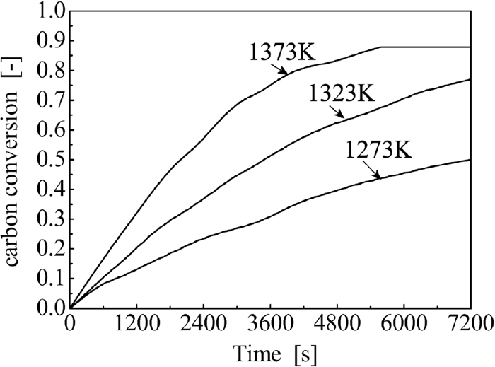
Variation of carbon conversion against time of sample E under different temperatures.
For a kinetic study, it is important to know whether carbon gasification in the briquette is controlled by chemical reaction, by external gas diffusion, or by internal gas diffusion. Under the investigated temperature range, increasing the gas flow rate had a negligible effect on the plots of carbon conversion against time (Fig. 10), indicating that the influence of the external gas diffusion had been removed. The diameter and height of the briquette were equal, so the shape of the briquette could be approximated as a sphere. The gasification kinetics of the carbon in the briquette can thus be described using the unreacted shrinking core model. Supposing that the model is based on control by chemical reaction, it is described by Eq. (8); supposing that the model is based on control by internal gas diffusion through the product layer (metallic iron layer), it is described by Eq. (9).24)
| (8) |
| (9) |
The results of the reaction controlling mechanism estimation of sample E using Eqs. (8) and (9) are shown in Fig. 11 and in Fig. 12, respectively. In Figs. 11 and 12, linear regression lines were used to highlight possible correlations. The larger coefficient of determination (R-Square) under each temperature was foucused as the dominant mechanism shows a linear plot. Thus, the dominant mechanism of carbon gasification in sample E was chemical reaction.
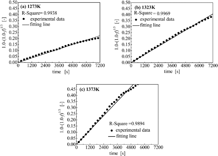
Results of gasification controlling mechanism estimation using Eq. (8).

Results of gasification controlling mechanism estimation using Eq. (9).
The value of k under each temperature shown in Fig. 11 was calculated using the slope of the corresponding fitting line; they were 3.11 × 10⁻⁵, 5.64 × 10⁻⁵, and 9.77 × 10⁻⁵ (1/s) under 1273, 1323, and 1373 K, respectively. It was found that lnk had a linear relationship to 10000/T as depicted in Fig. 13, so it can be stated that the gasification of the carbon in the briquette followed the Arrhenius law, expressed as Eq. (10).
| (10) |
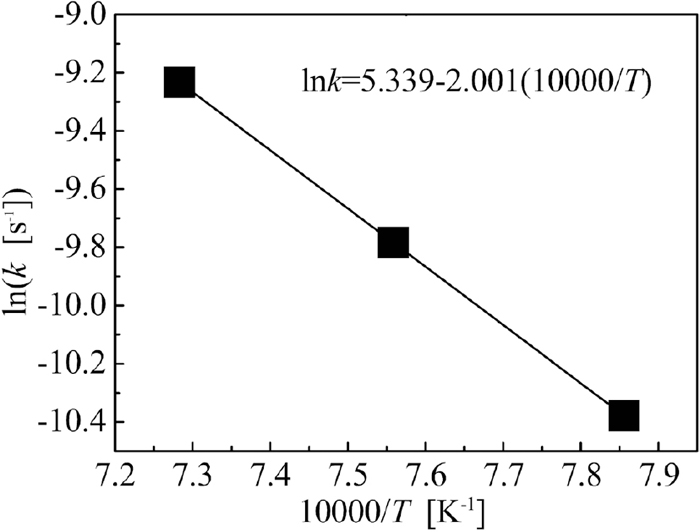
Arrhenius plot calculated using Eq. (10).
From the slope of the fitting line in Fig. 13, the activation energy of carbon gasification in sample E was calculated to be 166 kJ/mol. The activation energy of conventional coke gasification is usually greater than 200 kJ/mol.13) Compared to the conventional coke, the activation energy of carbon gasification in sample E is lower, reflecting that sample E has a much higher CO2 reactivity. Iron matter is usually considered to have a catalytic effect on the carbon solution-loss reaction. In the briquette, the fresh iron grains closely adhered to the surfaces of the carbon particles, forming many activated sites; accordingly, the carbon gasification could be intensified.
3.4. Surface Microstructure Evolution of HCMB in GasificationIn BF operation, pulverization of the burden must be avoided for it could reduce gas or liquid permeability of the burden bed. The microstructure evolution of the side-surface of sample E was examined under a temperature of 1373 K and an atmosphere of 80 vol%CO and 20vol%CO2; the results are shown in Fig. 14. In the initial stage, short iron fibers filled in the gap between carbon particles (Fig. 14(a)). With the increase of time, the short iron fibers moved closer, and some coalesced together, forming long iron fibers (Fig. 14(b)), as the carbon particles shrank. With time further extended, the iron fibers entwined around the carbon particles (Fig. 14(c)). By the end of the test, the carbon particles disappeared, and the iron fibers collapsed, forming a porous iron crust with gangue (coal ash) in the pores (Fig. 14(d)). The above analysis indicated that pulverization of the briquette would not occur in the BF.

Microstructure evolution of the side surface of sample E in gasification: (a) 0, (b) 30, (c) 60, and (d) 90 min.
The effect of applying the optimally prepared HCMB (sample E) was evaluated through numerical simulations. The simulations were carried out using the model developed by Tang and colleagues. Details of the employed model were described in refs. 25,26. Only CO, CO2, and N2 were included as BF gas components in the present study. The blast furnace for simulation had an inner volume of 2500 m3, producing 6250 ton/day of hot metal.
Two cases (case A and case B) were simulated. Case A reflects BF operation under normal conditions, and the operation parameters of the BF are given in ref. 26. Case B reflects BF operation with HCMB charging. In case B, HCMB of 84 kg was mixed into 1680 kg ore (the ore rate). The other operation parameters in case B were the same as those in case A, except that the required coke rate was determined by trial and error. In the model, gasification rate of the carbon from HCMB in the solid phase was described using Eq. (11). The results of the two cases are given in Table 6.
| (11) |
| Variable | Case A | Case B |
|---|---|---|
| Productivity (tHM/day) | 6250 | 6643 |
| Top gas temperature (K) | 620 | 578 |
| Top gas utilization effcieny (%) | 45.5 | 44.0 |
| Fuel rate (kg/tHM) | Coke:335, PC:180 Carbon from HCMB:0 | Coke:303,PC:169, Carbon from HCMB:19.8 |
| Hot metal temperature (K) | 1723 | 1723 |
*tHM: ton hot metal.
In Table 6, the increase of BF productivity in case B is due to the metallic iron from the HCMB. It can be seen that, after mixing HCMB into the ore burden in the BF operation, the top gas temperature showed a considerable drop of 42 K, and top gas utilization efficiency showed a decrease of only 1.5%. Mixing HCMB into the ore burden resulted in a considerable drop in coke rate from 335 to 307 kg/tHM; however, it should be noted that the metallic iron from HCMB had been included in the coke rate calculation of case B.
The profile of the HCMB gasification rate above CZ in case B is shown in Fig. 15(a). The gasification of the HCMB was mainly concentrated in the region near the CZ. The simulation results of case B indicated that the gasification level of the carbon in the briquette reached approximately 75%. Figure 15(b) shows the comparison of coke gasification-rate profiles above the CZ between the two cases. After mixing HCMB into the ore burden, coke gasification was suppressed (e.g., the area with a rate (absolute value) of greater than 0.009 kg/(m3·s) in case B is smaller than that in case A). Figure. 15(c) shows the comparison of the profiles of the ore reduction fraction between the two cases. Mixing HCMB into the ore burden exhibited an intensification effect on the ore reduction (e.g., the location of the contour line of 0.9 is higher in case B than in case A, and the lines of 0.8 and 0.6 are much closer in case B than in case A).

Simulation results of case A and case B: (a) profile of the HCMB gasification rate in case B, (b) comparison of profiles of coke gasification rate above CZ between the two cases; and (c) comparison of profiles of ore reduction fraction above CZ between the two cases.
The distributions of coke consumption in the two cases were then estimated, and these are given in Table 7. It can be observed that, by mixing 5% HCMB into the ore burden, approximately 12.5 kg of coke could be saved for producing one ton of hot metal from the ore.
| Case A | Case B | |
|---|---|---|
| Combustion | 148.0 kg/tHM | 148.0 kg/(1.063 tHM) |
| Gasification above CZ | 14.7 kg/tHM | 11.3 kg/(1.063 tHM) |
| Consumption below CZ by molten FeO | 105.1 kg/tHM | 96.0 kg/(1.063 tHM) |
| Other reactions | 67.2 kg/tHM | 67.2 kg/(1.063 tHM) |
| Total | 335.0 kg/tHM | 322.5 kg/(1.063 tHM) |
* 1. In Case B, coke conumption rate was calculated on the basis of 1.063 tHM to remove the influence of the metallic iron from the HCMB. 2. The coke is with a carbon content of 90 wt%.
The HCMB had a carbon content of 8 wt% when it reached the CZ. It was assumed that the left carbon was only for the carburization of the metallic iron introduced by the HCMB.
The above analysis shows that, in addition to improving BF productivity, mixing HCMB into the ore burden exhibits additional benefits for BF operation. These are the following: (1) the reduction of ore above the CZ is prompted; (2) the gasification of the lump coke above the CZ is weakened; and (3) the carbon content of the HCMB is low when it reaches the CZ, indicating that its melting would not influence the permeability of gas and liquid in the BF’s lower part. Of course, finding the optimal mixing level of HCMB in the ore burden needs further investigation.
HCMB has been prepared for BF application. Its gasification behavior under conditions simulating the in-furnace enviroment of the BF was investigated and its application in the BF were evaluated. The following conclusions can be drawn:
(1) The HCMB can be optimally prepared with mhematite/mcoal of 2.0. The optimally prepared HCMB had a carbon content of 25.6 wt%, and both its CS and CSR were greater than 1200 N/briquette. Its quality met the BF requirements.
(2) The threshold temperature of the optimally prepared HCMB was approximately 973 K, and the activation energy of carbon gasification in the briquette was 166 kJ/mol. Compared to conventional coke, its threshold temperature is lower, and its CO2 reactivity is higher.
(3) During gasification, a porous crust was formed, caldding the briquette, so the pulverization of the HCMB could not occur.
(4) The simulation results indicated that mixing HCMB into ore burden, at a suitable level, could prompt ore reduction and suppress coke gasification above the CZ. For a BF of 2500 m3 with a productivity of 6250 tHM/day, 12.5 kg of coke could be saved for producing one ton of hot metal from the ore.
This work was supported by the National Natural Science Foundation of China (No. 51144010) and the State Key Laboratory of Advanced Metallurgy, USTB (No. 41617010).