1. Introduction
Adopting effective measures to promote the columnar to equiaxed transition (CET) during the solidification stage of steel have attracted much attention.1,2,3) Among the methods of promoting CET,4,5,6,7) stirring of the melt by time-varying magnetic fields is particularly attractive due to the completely contactless feature and flexible tailoring of the magnetic fields themselves.8,9,10,11) The flow induced by the melt stirring can penetrate the mushy zone, remelt the dendrite arms and decrease the temperature gradient in the melts, thus favoring the CET.12)
In contrast to the time-varying magnetic fields, static magnetic fields are always used to suppress the flow due to the braking effect of the Lorentz force.13) Based on the Seebeck effect, however, a thermoelectric magnetic convection (TEMC) can be induced in the mushy zone under the static magnetic field.14) It is attributed to a thermoelectric magnetic force (TEMF) acting on the melts. The TEMF results from interaction between the thermoelectric current (TEC) near the liquid/solid interface and the applied static magnetic field. On the other hand, the TEMF imposed on dendrites and equiaxed grains breaks the dendrites and drives the motion of dendrite fragments and equiaxed grains in the mushy zone.15,16,17) Obviously, above-mentioned effects result in a promotion of the CET.18) Therefore, the CET in the absence of inoculation substances was obtained in the directional solidification of Al-based alloys,19,20) Pb-Sn alloys18) and Ni-based superalloys21) under axial static magnetic field (ASMF). The effect of ASMF on the CET in GCr18Mo steel during directional solidification at low growth speeds (5–20 μm/s) has also been investigated in our previous work.22) The results have shown that the applied ASMF has enhanced the CET of GCr18Mo steel. However, the mechanism for the CET with ASMF is roughly described from a macro perspective. In addition, the CET in the steel under ASMF is affected by the local thermal parameters like the temperature gradient in the melts and the growth speed of the dendrites, together with the magnetic field intensity. Further effort is required to explore the process window and better control the parameters dominating and resulting the CET affected by ASMF in industry.
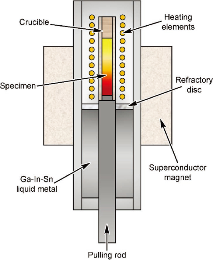
The goals of this work are described below. First, to assess the influence of the parameters on the CET, a heat-resistant Bridgman-Stockbarger type furnace has been installed in the static superconductor magnet. Since the intensity of the magnetic field, the temperature of the furnace and the growth speed could be controlled, the effects of the three parameters on the CET could be investigated independently. Second, the experimental results have been interpreted with the help of the numerical simulations performed with the software COMSOL. Third, combining both experimental and simulation results, a detail mechanism for the CET has been discussed. Finally, we attempt to give a process window for the CET of GCr18Mo steel with ASMF.
3. Results and Discussion
3.1. Effects of the Parameters on the CET with ASMF
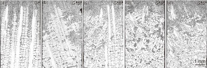
Figure 2 shows that microstructures of GCr18Mo steel at growth speed of 10 μm/s and various ASMF intensities under the 68 K/cm temperature gradient. With increasing intensity of ASMF, columnar grains gradually become equiaxed grains. When ASMF is applied, regular columnar dendrites are destroyed and tend to transform into equiaxed dendrites.
The dendrites are all regular at various temperature gradients without ASMF from the microstructures near the liquid/solid interface as displayed in Fig. 3. Columnar dendrites degenerate and transform into equiaxed dendrites as the temperature gradient increases with the 4 T ASMF.
The microstructures of directionally solidified GCr18Mo steel at various growth speeds under the 104 K/cm temperature gradient with and without ASMF are exhibited in Fig. 4. The dendrite morphology without ASMF is regular and columnar. With decreasing the growth speed under ASMF, columnar grains gradually become equiaxed grains.
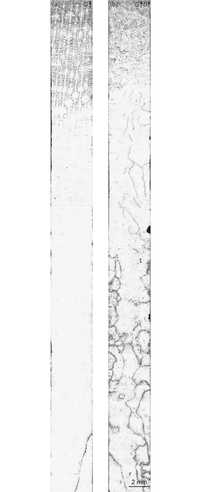
Longitudinal solidification structures of directionally solidified GCr18Mo steel at growth speed of 20 μm/s under the 68 K/cm temperature gradient without and with 4 T ASMF are shown in Fig. 5. The CET induced by ASMF tend to produce the grain refinement.
Based on above experimental results, we perform numerical simulations on the TEMF imposed on dendrites and melts. To calculate the TECs at the solid/liquid interface during directional solidification, a complementary term is added to Ohm’s law:23)
Where j, σ, ∇V, S and ∇T are the TEC density, the electrical conductivity, the electric scalar potential, the absolute thermoelectric power and temperature gradient, respectively. S∇T is the contribution of the TEC. j satisfies the continuity equation:
From the electric current continuity, TEC should flow through the solid (s) and liquid (l) simultaneously, so that TEMF exists in both phases (Fs and Fl) with ASMF (B) and can be respectively expressed as:
The thermoelectric magnetic convection (TEMC) can be described by inserting an external volume force term to the Navier-Stokes equation:
|
∂(
ρu
)
∂t
+ρ(
u⋅∇
)
u=-∇p+ρg+μ
∇
2
u+j×B
| (5) |
together with the conservation of mass assuming the liquid is incompressible:
Where ρ is the density, u denotes the velocity of the moving substance in a magnetic field, p is the pressure, g is the gravitational acceleration and μ stands for the dynamic viscosity.
It should be noticed that u×B must be taken into account due to the electromotive force induced by TEMC.
More details regarding the equations and corresponding boundary conditions are described in the works.23,24) Based on the assumption of Kurz,25) geometric model of the computation domain of the solid/liquid interfaces was built. A prescribed interface, as a heuristic model, qualitatively explains how the TEC and TEMF are produced. The physical properties of GCr18Mo steel used in the numerical simulation are given in Table 1.26,27,28)
Table 1. Physical properties and parameters in numerical simulation.
| Parameter | Unit | Value in Solid | Value in Liquid |
|---|
| Absolute thermo-electric power (S) | V/K | −1×10⁻⁶ | −4×10⁻⁶ |
| Dynamic viscosity (μ) | Pa·s | − | 5.5×10⁻³ |
| Electrical conductivity (σ) | 1/(Ω·m) | 8.5×10⁵ | 7.2×10⁵ |
| Density (ρ) | Kg/m3 | 7.4×10³ | 7.02×10³ |
| Thermal conductivity (λ) | W/( m·K) | 32.5 | 31.2 |
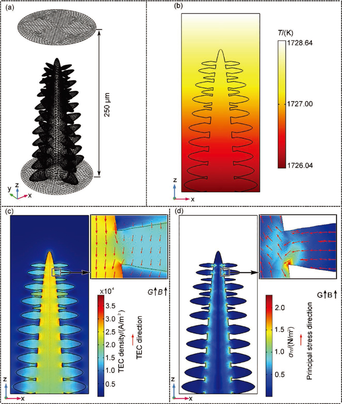
Figure 6 shows the numerical simulation for TEMF in a typical columnar dendrite of the directionally solidified GCr18Mo steel at pulling rate of 20 μm/s and temperature gradient of 104 K/cm with 5 T ASMF. The geometry of the computation domain of the typical columnar dendrite is shown in Fig. 6(a). Figure 6(b) exhibits the distribution of the temperature. As shown in Fig. 6(c), the maximum density of the TEC appears in the secondary dendrite neck region. Figure 6(d) shows the distribution of the von Mises stress induced by TEMF in the typical columnar dendrite. This stress acts on the secondary dendrite neck.
Figures 7(a) and 7(b) show the geometry and the distribution of the temperature of the computation domain of regular solid/liquid interface at the growth speed of 50 μm/s and temperature gradient of 104 K/cm with the 5 T ASMF, respectively. The corresponding computed TECs in the liquid at the xz-plane are displayed in Fig. 7(c). The TEC forms the circuits along the cell and the large value of TEC density distributes around the dendrite tips and at the bottom of the mushy region. Figure 7(d) shows the general 3D view of the computed TEMC. Further examination into the fluid flow between the primary arms at yz-plane and the xy-plane is given in Figs. 7(e) and 7(f). Note that the fluid flows in a direction from the interdendritic spacing to the region ahead of the solidification front (Fig. 7(e)). In addition, a toroidal flow forms around the primary arm, and in the meanwhile a relatively high velocity appears along the edge of the sample (Fig. 7(f)). Furthermore, the distribution of the TEMC in the xz-plane is plotted in Fig. 7(g). It can be illustrated that the flow velocity increases along the positive z-axis. The reason for the small TEMC velocity at the large TEC density region in the bottom of the interdendritic spacing is that the direction of TEC is parallel to ASMF, not producing the TEMC (Eq. (5)).

For the mechanism of the CET without inoculants or any significant nuclei, Hellawell et al. defines five time- and temperature-dependent steps, starting with the detachment of side arms of primary arms in the mushy zone and ending with the blocking of the columnar front by a network of equiaxed grains.29) From this, we could deduce the mechanism of several keypoints: (1) dendritic side arms are separated from primary arms, (2) fragments are transported by interdendritic convection in the mushy zone, (3) fragments must survive and grow in the course, and (4) the advancing columnar solidification front is blocked by the these equiaxed grains reached a critical concentration. Under the action of ASMF, a Lorentz force, named as TEMF, affects the solidification processes ranging from a form of convection, transport of the solid phase in the liquid to strain and deformation of the solidified structure. For a given alloy, the TEMF (FTE) increases as the magnetic field intensity and the temperature gradient increase according to Eqs. (3) and (4).
On the one hand, the fragments in various alloys may be produced by several mechanisms: (1) ripening; (2) recalescence; (3) solute remelting of a dendrite neck; (4) mechanical deformation from various sources (gravity, buoyancy, liquid flow, and external deformation) combined with transgranular liquation cracking mechanisms; (5) catastrophic elastic remelting.30,31,32) Based on the catastrophic elastic remelting mechanism, the stress localized into the dendrite necks is induced by the TEMF, as another driving force for causing the dendrite to fragment (Fig. 6). On the other hand, the toroidal flow mainly exists in the interdendritic spacing of the mushy zone from the numerical results (Fig. 7). The fluid flow may transport some of the fragments from the interdendritic spacing to the region ahead of the solidification front (Fig. 7(e)). The advancing columnar front stops as soon as the concentration of the equiaxed grains has reached a critical value. Some other fragments may be trapped in the interdendritic spacing and then form new grains similar to Zimmermann’ analysis of the CET by using in-situ X-ray diagnostics.33) In addition, we have found that TEMF also cause a movement of equiaxed grains in suspension by using x-ray in situ and real-time observations under static magnetic field.34,35)
To gain more insight, the solidification microstructures and the maximum value of computed TEMC and the von Mises stress at various growth rates and magnetic field intensities under the temperature gradient of 104 K/cm are plotted in Fig. 8. The solidification microstructures obtained from the experiment show that the increase of magnetic field intensity contributes to the formation of equiaxed dendrites at relatively high growth speeds. The stress localized into the dendrite necks increases with increasing magnetic field intensity. In contrast with the stress, TEMC increases firstly and then decreases with increasing magnetic field intensity. However, the value of TEMC still above the growth speed. Notably, although there is a relatively high TEMC velocity under a low magnetic field intensity, no equiaxed dendrites have been formed at relatively high growth speeds. It may be attribute to the weak effect on the detachment of dendritic side arms induced by the stress localized into the dendrite necks.

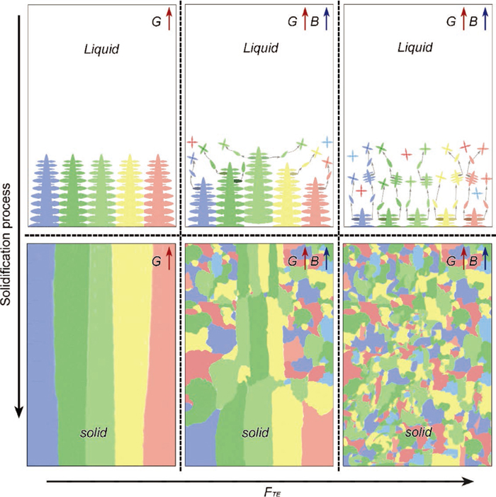
On the basis of the above results and analysis, we illustrate that how the solidification structure evolves at different solidification stages without and with ASMF (Fig. 9). As shown in Fig. 9, the columnar dendrites grow steadily and then finally form columnar grains without ASMF. When ASMF is applied, the fragments detach from the primary dendrites induced by the stress localized into the dendrite necks. Then the TEMC existed in the interdendritic spacing transports a part of the fragments from the interdendritic spacing to the region ahead of the solidification front, especially along the edge of the sample. As solidification progresses, these fragments grow up ahead of the columnar dendrite tips or in the interdendritic spacing. The advancing columnar solidification front will be blocked as soon as the concentration of the equiaxed crystals reaches a critical value. In this situation, most of the fragments tend to form new equiaxed grains.
3.3. The Process Window with ASMF
Hunt initially established the criterion of the CET.12) Fully equiaxed growth occurs when
|
G<0.617
N
0
1/3
[
1-
(
Δ
T
N
/Δ
T
c
)
3
]Δ
T
c
| (8) |
The structure is fully columnar when
|
G<0.617
(
100
N
0
)
1/3
[
1-
(
Δ
T
N
/Δ
T
c
)
3
]Δ
T
c
| (9) |
where
G is the temperature gradient,
N0 is the heterogeneous nuclei density, Δ
TN is supercooling necessary for nucleation, and Δ
Tc is constitutional undercooling on the dendrite tip.
Constitutional undercooling ΔTc is defined by Eqs. (10) and (11):
|
Δ
T
c
=
(
V
C
0
/A
)
1/2
| (10) |
where
C0 is the initial concentration,
V is the dendrite tip velocity,
D is the diffusion coefficient of solute element,
m is the liquidus slope,
k is the partitioning coefficient, and Γ is the Gibbs-Thomson parameter. The related parameters used in the present simulation are given in
Table 2.
25,28,36)
Table 2. The related parameters used in the CET map.
| Parameter | Unit | Value |
|---|
| Heterogeneous nuclei density (N0) | m−3 | 9×10⁸ |
| Supercooling necessary for nucleation(∆TN) | K | 1.5 |
| Diffusion coefficient (D) | m2/s | 4.79×10⁻⁹ |
| Partition coefficient (k) | − | 0.34 |
| Liquidus slope (m) | K/wt% | –78 |
| Gibbs-Thomson parameter (Γ) | K·m | 1.9×10⁻⁷ |
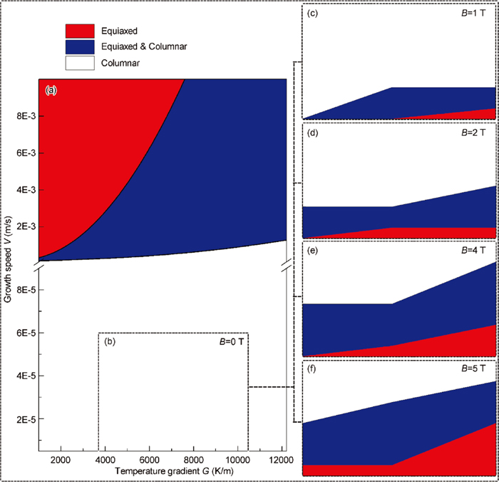
Figure 10 shows microstructure selection map for GCr18Mo steel calculated by the Hunt’s model (a) and experimentally obtained from the 0 T (b), 1 T (c), 2 T (d), 4 T (e) and 5 T (f) ASMFs, when the imposed temperature gradient (G) or growth speed (V) are varied. The experimental results without ASMF (b) is consistent with the calculation from the Hunt’s model (a), when the temperature gradient and growth rate in the black dotted bordered rectangle are applied. The increasing magnetic field intensity contributes to extend the range for process parameters (G and V) of equiaxed grains formed. As in directional growth, the product, G·V, is equivalent to the cooling rate,
T
˙
, controlling the scale of the solidification microstructures formed.25) In this work, the value of the cooling rate at temperature gradient of 104 K/cm can reach up to 0.312 K/s, below which the solidification microstructures forms equiaxed grains with 5 T ASMF. Comparison of this value with the cooling rates of the steel casting in the range between 10−1 and 100 K/s demonstrates that ASMF may potentially be used to control the CET in industry.