Steelmaking
Decarburization of Pig Iron in Synthetic BOF Converter Slag
2019 年 59 巻 1 号 p. 46-50
詳細
2019 年 59 巻 1 号 p. 46-50
The paper presents a study on the decarburization of pig iron droplets in synthetic BOF slag. The effects of droplet size and slag composition were studied. The results show evidently that the decarburization is very fast in general. One gram of pig iron is mostly decarburized within one minute. The reaction is shown to be faster when many small droplets were employed instead of one big droplet with equal total mass. This is explained by the bigger interfacial area between the liquid slag and the pig iron of the many small particles. It is also interesting to see that the decarburizing reaction in the slag having lower dynamic viscosity and higher FeO activity is slower than in the slag with higher viscosity and lower FeO activity. The slower reaction could be explained by the longer incubation time in this slag.
The fundamentals of the BOF converter process have been studied for a long time, and the decarburization has been the topic for many researchers.1,2,3,4,5,6,7,8,9,10,11,12,13,14,15,16,17,18,19,20) The main purpose of the BOF furnace is to decarburize and dephosphorize the hot metal delivered from the blast furnace.21) As oxygen is blown on the top surface of the metal bath, metal droplets splash into the slag composing mostly of FeO, CaO and SiO2. The dissolved carbon in the hot metal will reduce the FeO due to the decarburizing Reaction (1), which generates CO gas.
| (1) |
The CO gas gets trapped in the liquid slag phase, creating a foam. The foaming slag isolates the heat in the melt and protects the lining of the furnace wall.
Although the decarburization process has been extensively studied, questions are still remained unanswered. Some investigations have used x-ray fluoroscopy technique to study the decarburization process.3,4,6,19) They indicate that a gas halo is formed around the hot metal droplet and that the droplet is swelling due to gas formation. The theory and effects of these phenomena are still being discussed and the importance is uncertain. Some researcher believe that the decarburization occurs mostly in the gas halo,8) while other believe that the contact area between the hot metal and liquid slag phase is more important.21) The chaotic environment in the BOF makes an on-line investigation very difficult. Laboratory work has been carried out to study the FeO reduction or decarburization of hot metal to give some clarity of the reaction mechanisms in the BOF. In these experiments, either carbon containing iron,1,5,6,13) solid carbon,4,10,12,17) or different oxygen partial pressure14) has been used as reacting substance. Experiments to study the effect of P and S has also been carried out,7,15,16,20) which is an interesting part of the topic as the demands on steel grades are increasing.
On the whole, everyone agrees that the emulsion plays a profound role for the BOF process. Yet today, one of the most discussed topics in the matter is whether Reaction (1) mostly occurs in the hot metal bath and slag interface or in the emulsion between metal droplets and slag phase. A study of the reaction rate between hot metal droplets and slag would threw some lights on the reactions taking place in the converter and help to understand the contribution of slag-droplet reaction in decarburization.
In this work, the decarburization rate of hot metal droplets in two different BOF slags is to be studied. The reaction is described as a function of time. Different iron droplet sizes are employed to examine the effect of the droplet size, i.e. interfacial area between slag and metal as well as mass transfer in the droplet. The foaming height generated by Reaction (1) is another objective of the present work.
A vertical high-temperature tube furnace was employed for the experiments. A schematic description of the setup can be seen in Fig. 1. The furnace was equipped with Kanthal super heating elements which generated a hot zone of approximately 10 cm, where the temperature was constant at 1873 K. An alumina tube with an inner diameter of 0.07 m acted as reaction tube. A cooling chamber was mounted on top of the reaction tube where the sample was kept during the heating of the furnace. After the reaction, the sample was raised rapidly to the chamber for fast cooling.
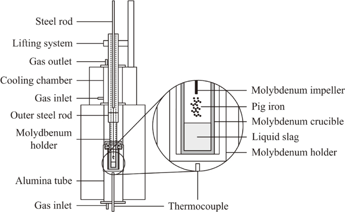
Experimental setup.
Pig iron containing 3.9 wt% C was provided by SSAB Oxelösund and granulated by Uvån Hagfors Teknologi AB. A complete list of the composition is shown in Table 1. As can be seen, the silicon and manganese contents are 0.22 and 0.21 wt% respectively. These small amounts are only expected to play a minor role on the incubation time of the decarburizing reaction. Also, since all experiments are carried out using the same pig iron, the condition is assumed to be the same for all samples.
| Alloy | wt% | Alloy | wt% |
|---|---|---|---|
| C | 3.9 | Ti | 0.023 |
| Si | 0.22 | Nb | 0.001 |
| Mn | 0.21 | Cu | 0.009 |
| P | 0.048 | Sn | 0.001 |
| S | 0.042 | Al | 0.13 |
| Cr | 0.4 | B | 0.001 |
| Ni | 0.098 | Ca | <0.0005 |
| Mo | 0.011 | Mg | <0.0001 |
| W | 0.001 | V | 0.2 |
| Co | 0.013 | Fe | Balance |
Totally, 1 gram of the pig iron was used in each experiment. It was decided to compare the decarburization using different pig iron sizes. Therefore pieces of approximately Ø2 mm or Ø6 mm was selected (with some small variation). For the Ø2 mm pieces, approximately 20 pieces were needed, while only one droplet of the Ø6 mm was necessary to reach 1 gram. Different slags were prepared to see the effect of slag composition with different physical properties.
Two slag compositions relevant to the BOF process were chosen.21) The slags represent two different periods of the process. While slag Y corresponds to the initial period of oxygen blowing, slag X represents the composition in the later stage of the process. The slag compositions can be read in Table 2, where the components are given in wt%. The dynamic viscosity at 1673 K, given in Pa∙s, and FeO activities at 1823 K for the slags are also given in the table.22)
| Slag X | Slag Y | |
|---|---|---|
| FeO | 25 | 45 |
| CaO | 43 | 22 |
| SiO2 | 32 | 33 |
| aFeO | 0.5 | 0.6 |
| μdynamic | 0.09 | 0.06 |
The FeO was produced by heating Fe–Fe2O3 mixture with 51 atom% oxygen in a closed iron crucible in argon atmosphere at 1143 K and kept there for approximately 60 hours. The sintered FeO body was then crushed to millimeter sized particles. XRD analysis confirmed the formation of FeO. CaO was calcined at 1173 K for approximately 10 hours. SiO2 was dried at 383 K for approximately 24 hours before usage.
To ensure an inert atmosphere during the experiment, the furnace was vacuumed and flushed with argon before the experiment was carried out. A molybdenum crucible with 90 grams of slag was then lowered down to the hot zone for pre-melting at 1873 K. The droplets of pig iron was fastened to a steel rod with plastic foil and kept in the cooling chamber where the temperature was approximately 330 K. After one hour of pre-melting, the slag was completely liquid and homogeneous as revealed by previous experiments. The rod with pig iron was then lowered down fast to a position close to the hot zone. The high temperature melted the plastic foil and released the droplets of pig iron instantly. The iron droplets fell down into the liquid slag. The reaction was then started and the FeO was reduced by the carbon dissolved in the pig iron. The reaction was interrupted at different reaction times by raising the sample rapidly into the cooling chamber. The solidification of the metal droplets would in reality stopped the decarburization. The samples were raised to the cooling chamber after 5, 10, 20 or 30 seconds to study the decarburization as a function of time. However, since the pig iron doesn’t solidify directly when reaching the cooling chamber, a reference temperature measurement was made for Slag X, to obtain better understanding of the reaction time.
After the experiments, the highest level of the foamed slag was easily detected as slag residues remained in the molybdenum setup. The foaming heights were therefore easily measured using a ruler. The steel was always found in the bottom of the crucible due to the big density difference between slag and steel. The good wettability between steel and molybdenum would also help to keep the liquid iron at the bottom.
The steel could more or less be easily removed by picking on the surface with a tool until pieces were peeled off. To avoid to bring along molybdenum pieces, a magnet was used to identify the iron. When necessary, a pneumatic die grinder was employed to remove slag and molybdenum pieces from the iron pieces. All the collected iron was kept in a desiccator before sending the samples for analysis at Degerfors Laboratorium AB. The carbon content was measured using the carbon combustion analysis ASTM E1019.
2.2. Reference Temperature MeasurementsThe reference temperature measurements were carried out in the same manner as the other experiments. 90 grams of slag X was kept in the hot zone at 1873 K for one hour. Instead of dropping the iron droplets into the melt, a second thermocouple of type C was placed above the inner molybdenum crucible, where the temperature was measured to be 1793 K. The sample along with the second thermocouple was then lifted fast to the cooling chamber and the temperature above the crucible was logged.
2.3. Incubation Time of ReactionAn induction furnace was employed to study the incubation time of the decarburizing reaction. The incubation time was defined as the time from a droplet being exposed to the slag to the moment when a gas bubble (reaction product) is first observed. A schematic description of the setup can be seen in Fig. 2. The graphite crucible was painted with Yttrium oxide to avoid heavy oxidation. An MgO crucible was used as inner crucible to avoid any contact between the FeO-containing slag and graphite crucible to prohibit any reaction between the slag and the crucible. The slag was put into the MgO crucible and heated to 1873 K, measured with a calibrated infrared temperature measurement of model thermoMETER CTM-1SF75-C3. Immediately when the temperature was reached and all slag was molten, 1 gram of pig iron (droplet size Ø2 mm) was dropped into the slag via a thin silica tube. The experiment was carried out as fast as possible to avoid the effect of dissolved MgO into the slag. A video camera equipped with a solar filter recorded the processes from above. The incubation time was measured from the moment the pig iron reached the liquid slag until bubbles from the reaction could be observed on the slag surface on the video. Ocular examination of the MgO crucibles after the experiments revealed that the crucibles were not eroded by the slag to any appreciate extent.
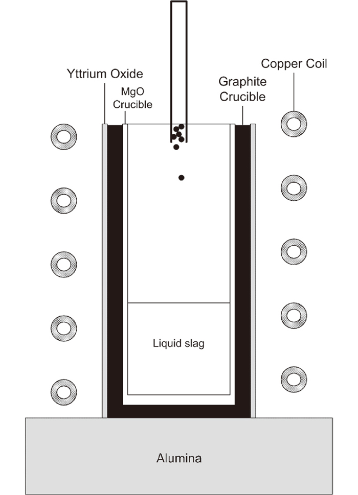
Experimental setup for incubation time measurements.
Since the molybdenum setup (sample holder along with the sample) is quite big. The cooling rate is therefore as expected rather slow, see the temperature profile in Fig. 3.
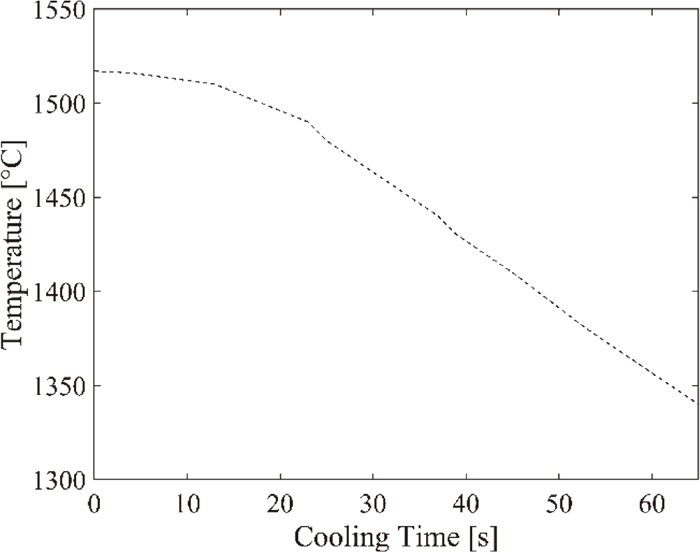
Temperature profile during cooling.
The figure shows that the cooling rate is very slow during the first 10 seconds, after which the cooling rate accelerate to a maximum of approximately 3.3 degrees/second. Remember that the second thermocouple is placed just above the crucible, where the temperature is approximately 70 degrees lower than in the sample. Since pure iron starts to solidify at approximately 1809 K, it is therefore a good approximation that the reaction will stop about 35 seconds after the sample is raised from the hot zone in the reaction tube. At this time, the temperature has dropped about 70 degrees, and inside the crucible the temperature can be assumed to be at approximately 1803 K. With this reasoning, the reaction times are actually 40, 45, 55 and 65 seconds, instead of 5, 10, 20 and 30 seconds.
The results from the decarburization experiments can be seen in Fig. 4. The black markers show the analyzed values, while the dotted lines are corresponding exponential fitting curves calculated with MATLAB fitting function. The decarburization is in general fast. It can be seen that the reaction is a little faster for small particles than big particles in slag X. It can also be seen that the decarburization is faster for slag X compared to in slag Y.
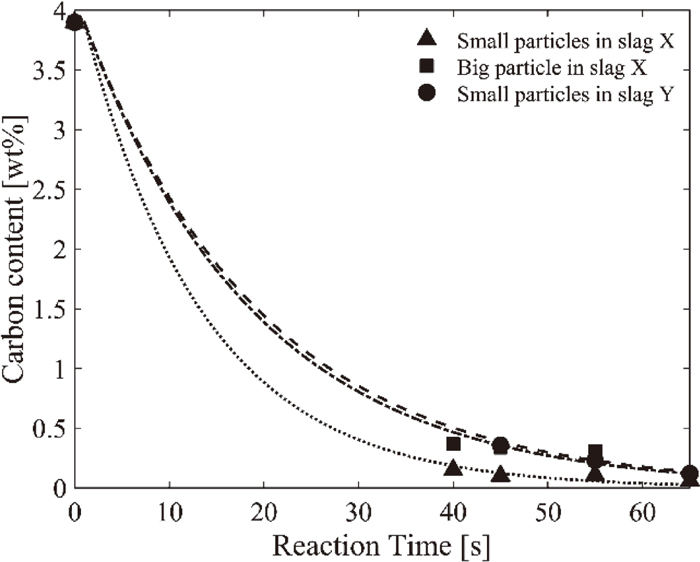
Decarburization rate of pig iron in BOF slags.
The more aggressive decarburization in slag X can also be seen by studying the foaming heights, shown in Table 3. The foaming was very aggressive, and could reach heights even higher than the crucible height, luckily the molybdenum setup could keep the foam inside the setup. Sometimes the foaming height could reach up to 220 mm, remember that the crucible is only 130 mm. See all foaming heights in Table 3. A higher foam is generated for the experiments where small particles were used compared to big particles. This is expected since the big particle has smaller surface area, and hence smaller interface between steel and slag, where the decarburizing reaction occur. This results in a slower gas generation, which may decrease the foaming height. It is also shown that Slag X generates a higher foam compared to Slag Y.
| Slag | Particle diameter [mm] | Reaction time [s] | Foaming height [mm] |
|---|---|---|---|
| Slag X | 2 | 40 | 130 |
| . | . | 45 | 200 |
| . | . | 55 | 220 |
| . | . | 65 | 210 |
| . | 5 | 40 | 130 |
| . | . | 45 | 140 |
| . | . | 55 | 140 |
| Slag Y | 2 | 45 | 140 |
| . | . | 55 | 180 |
| . | . | 65 | 130 |
The experiments carried out in the induction furnace shows that the incubation time for slag X is approximately 1–3 seconds, while it is 7–9 seconds in slag Y. It is difficult to state an exact time for the incubation time. The gas generation is clear in the film, but when the first bubble is shown on top of the liquid surface, the reaction is already ongoing.
Regarding the decarburizing reaction, the possible controlling mechanisms are: (1) the interfacial area between droplet and slag, (2) the mass transfer inside the droplet and slag, (3) the detachment of CO-gas from the droplet and (4) the partial pressure of CO-gas in the system. The melting process of the hot metal is also important, since diffusion in solid phase is much slower than convection in liquid.
It can be interesting to mention that since only 1 gram of 3.9 wt% carbon containing pig iron was dropped into the 90 gram slag, the composition of the slag does not change substantially, only 0.02%. It is impressive to discover that the amount of gas that is theoretically possible to be generated by the carbon is still 7.5∙10−5 Nm3, if the decarburizing reaction occur according to Reaction (1). It is therefore of course important that the gas phase can detach from the droplets and escape from the system to keep a low enough partial pressure of CO for the reaction to continue.
Figure 4 displays the decarburization results. Since only a few similar experiments have been carried out before, it is difficult to compare the results to other. Gaye and Riboud5) showed similar decarburization rate, but they used a different slag with much higher CaO/SiO2 ratio (almost 10) and lower temperature. Gare and Hazeldean6) used a similar setup to the one used in this work, but the experiment was carried out at lower temperature and with lower amount of iron oxide. The reaction rate is a little lower as expected.
The results in Fig. 4 show that the reaction rate is faster when many small particles are used instead of one big particle. This can possibly be explained by the fact that many small particles have a total surface area that is much bigger than one big particle with the same total volume. Also, the mass transfer is much shorter in a small droplet compared to a big one. Finally, the melting procedure of small droplets is faster, the reaction may commence earlier than the case of a big particle. Besides the bigger surface area and shorter mass transfer, some other factors might also contribute to the different reaction rates. For example, the gas generation and detachment from the metal/slag interface, and the change in the interfacial tension due to the metal/slag reaction makes the interfacial area difficult to evaluate. Also, if the mass transfer in the metal controls the reaction rate, different slags may show similar decarburization rate. Therefore, to further clarify the situation, more delicate experiments are needed.
It is also worthwhile to mention that iron has a very high surface tension of 1788 N/m.22) Hence, they are unlikely to be crushed into smaller ones by collision with bubbles.
Figure 4 also indicates that the reaction rate is faster in slag X compared to slag Y. This is rather surprising. The interfacial area and melting procedure are the same in both slags when Ø2 mm droplets were employed. The differences between the slags are the dynamic viscosity and activity of FeO. Slag Y has a lower viscosity than slag X, 0.06 Pa∙s and 0.09 Pa∙s respectively. The mass transfer is thus faster in slag Y. The lower dynamic viscosity should also facilitate the removal of the bubbles from the pig iron, due to lower drag force. Slag Y also has a higher FeO activity compared to slag X, 0.5 and 0.6 respectively. A higher FeO activity would increase the FeO’s driving force to react with the carbon, but yet the decarburization is shown to be faster in slag X. The more aggressive decarburization in slag X is also shown by the foaming behavior of the two slags. In Table 3, it can be seen that the foaming heights in slag X are always higher compared to in slag Y. The higher foaming height could be due to a faster gas generation and/or the higher viscosity in which the gas is trapped for a longer time. Although, in combination with the results from Fig. 4, a faster gas generation and hence a faster decarburization in slag X is more likely. The small difference in dynamic viscosity of the two slags might not play a major role.
The explanation for the faster reaction in slag X could be due to the incubation time. Even though it is difficult to measure the exact incubation time with this type of measurement, it is evident that the reaction starts faster in slag X compared to in slag Y. The first bubbles were caught on the film already after a couple of seconds in slag X, while it took almost 10 seconds for the bubbles to appear in slag Y. As mentioned in the experimental part, the silicon and manganese content should not affect the incubation time too much. Although, in combination with the melting period of the pig iron, a delay of the decarburizing reaction is to be expected. In addition, since the composition of the pig iron is the same in both cases, something else plays a major role here. The difference in incubation time can well explain the difference in the decarburization rate and foaming behavior that could be observed. In fact, if the reaction starts later, the actual reaction time would be shorter in slag Y. Hence, the reaction rate might be more equal than the results indicate. In view of the BOF process, of course, if the reaction time is rather short, the incubation time is very important.
More research has to be carried out to gain an insight into the incubation time and its effect on the reaction.
In this work, the decarburization process was studied. Pig iron containing 3.9 wt% carbon was dropped into FeO-containing slags kept in a molybdenum crucible. Different sizes of the pig iron were employed to study the effect of droplet size. It was found that small droplets are decarburized faster than one big droplet with the same total mass. This can possibly be explained by the bigger surface area, shorter mass transfer or faster melting time of the small droplets. Further studies are although recommended to improve the understanding. The effect of the FeO content in the slag on the rate of decarburization was also examined. Surprisingly, the decarburization was faster in slag X than in slag Y, even though the latter had higher FeO activity and lower viscosity. A lower viscosity would lead to a faster mass transfer in the slag and a faster detachment of the bubbles. The reason for the slower reaction in slag Y was found to be due to the longer incubation time for the reaction. Despite of the difference in reaction rate in the two slags, the reaction took place very fast in both case. It took only less than 60 seconds before most of the carbon had been removed in both cases.