Abstract
In steel industry, product number recognition is necessary for factory automation. Before final production, the billet identification number (BIN) should be checked to prevent mixing billets of different material. There are two types of BINs, namely, paint-type and sticker-type BINs. In addition, the BIN comprises seven to nine alphanumeric characters except the letters I and O. The BIN may be rotated in various directions. Therefore, for proper recognition and accident prevention, end-to-end BIN recognition system that uses the deep learning is proposed. Specifically, interpretation and sticker extraction modules are developed. Furthermore, the fully convolutional network (FCN) with deconvolution layer is used and optimized. To increase the BIN recognition accuracy, the FCN was simulated for various structures and was transferred from the pre-trained model. The BIN is identified by the trained FCN model and interpretation module. If the BIN is sticker-type, it is inferred after the sticker region is extracted by the sticker extraction module. The accuracy of the proposed system was shown to be approximately 99.59% in an eight-day period.
1. Introduction
Recently, several studies have been conducted on computer vision systems for the factory automation in steel industry.1,2,3,4,5,6) To achieve factory automation, it is important to develop a system that recognizes the steel product identification number, which is the analogue of a person’s name,7,8,9,10) as this should be managed and tracked for customized production. Among steel products, billets are considered in this study. They are extracted from blooms in hot rolling mills, or produced by casting processes. Before the next hot rolling process, the billet identification number (BIN) should be checked to prevent mixing unwanted billets. Significant loss could be caused by material mixing owing to BIN mis-recognition.
BIN recognition involves several challenges. Specifically, BINs have various configurations. In Fig. 1, the BINs have two marking types, namely, paint marking and sticker marking, and may be rotated because a crane moves the billet from the yard onto the roller, which is connected to hot rolling mill. BINs of paint type are inscribed by an auto-marking machine or template-marking plate and have various font styles according to the factory that produces the billets. In addition, the BIN is a combination of alphanumeric characters except the letters I and O. Moreover, BINs may be damaged by pre-processing, such as water cooling and grinding for removal of surface defects or scraps. Furthermore, the lighting condition varies.

To recognize the BIN, conventional algorithms have been introduced.11,12,13,14,15) These algorithms use rule-based methods, the Karhunen–Loeve transform, support vector machine (SVM) and optical flow. The recognition accuracy of conventional algorithms may vary according to the designer because performance is determined by design features. Recently, deep learning algorithms, which do not have this drawback, have outperformed other methods in the steel product number recognition.16) In previous studies,17) the fully convolutional network18) (FCN) was employed in slab identification number recognition. In ther present study, a novel BIN recognition system is proposed based on these studies. The main contributions are: 1) An end-to-end BIN recognition system that can be applied in actual operation and 2) the recognition of a sticker-type as well as a print-type BINs that are rotated in various directions. The proposed system was optimized through various simulations and had high accuracy. The remainder of the paper is organized as follows. In Section 2, the proposed BIN recognition system is detailed. The simulation results are presented in Section 3. And, Section 4 concludes the paper.
2. Proposed Recognition System
2.1. Billet Image and Billet Identification Number
The billet images (480 (height) × 640 (width) 8-bit gray) were collected during 36 days of operation. A total of 28687 images were collected and comprised 26272 images for paint-type BINs and 2415 images for sticker-type BINs. The images show BINs on cross sections of the billets. Examples of images are shown in Fig. 1.
The paint-type BINs, which are imprinted by a marking machine or a template-marking plate, consist of eight or nine characters, and three fonts are used. The structure of paint-type BIN is as follows. The first character of the first row is a letter. In the second row, the first and forth characters are alphanumeric. The remaining characters of the first and second rows are numbers. In addition, a letter may or may not be inscribed in the third row. Here, the letter may be from A to Z, with the exception of I and O. The problem in recognizing paint-type BINs is that they could be blurred by several pre-processes.
Another form of BIN is sticker-type. It is generally used in purchased billets. It consists of seven characters, and the letter Z is fixed as the first character in the second row. However, the structure of sticker-type BINs may be the same as that of paint-type BINs such as Figs. 1(j) and 1(l) because the paint-type BIN is replaced with the sticker type when its quality is unacceptable. Furthermore, the sticker is manually attached to the front of the billet. Therefore, it may be rotated from 1 to 360°. Another problem is that it is difficult to obtain images of sticker-type BINs, as they do not frequently appear.
2.2. Fully Convolutional Networks and Ground Truth Data
A fully convolutional network (FCN) with deconvolution layers as pixel-to-pixel classifier18) isemployed for BIN recognition. FCNs are widely used in semantic segmentation and consist of convolution and pooling layers without fully-connected layer, which is generally used as the output layer of convolutional neural networks (CNNs). Therefore, FCNs have no limit on the input size because they do not use the fully-connected layer whose input size is fixed; thus, the whole image can be received as the input of the network. In addition, the output size of FCNs is same as the input size because the output is up-sampled by the deconvolution layer.18)
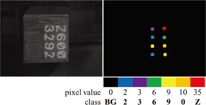
To train the FCN with deconvolution layer, a training set {(In, Gn): n= 1, …, N} is used consisting of pairs of input images In = {in(w, h): w = 1, …, W, h = 1 … .H} and ground truth data (GTD) Gn = {gn(w, h) = k: w = 1, …, W, h = 1 … .H, k = 0, …, K − 1}, where W is the width of the input images, H is the height of the input images, K is the number of classes to identify, and N represents the number of samples in the training set. Previously, position-based GTD was proposed owing to ease of labeling work and post-processing samplification.22) In the billet image, the character center coordinates (x, y) and character class k are required to generate GTD. In Fig. 2, the center and the pixel value of each circle represent the corresponding center and class of each character, respectively. In the training set, the mean and minimum values of character spacing were 50.37 and 27 pixels, respectively. Therefore, the radius of circle was chosen to be 10 pixels to prevent two circles from intersecting.
The proposed BIN recognition system was developed by using an FCN with deconvolution layer. To apply to an actual operation site, the focus was high accuracy and ease of use. Therefore, no deep neural network to check the orientation and the region of the BIN because different network structure and training process would be required. The paint-type and sticker-type BINs were separately trained with same network structure due to imbalanced data (considerably smaller number of sticker-type BINs).
In Fig. 3, the proposed BIN recognition system is composed of two trained models for paint-type and sicker-type BINs. To extract the BIN from the image, interpretation and sticker extraction modules are proposed.

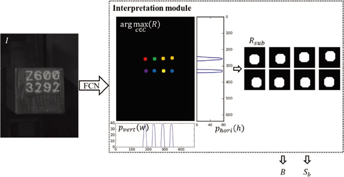
As you can see in Fig. 1, paint-type BIN has four directions (0, 90, 180 and 270°), and sticker-type BIN may be rotated in various directions (1 – 360°) because sticker is manually attached to the front of billet. To solve this problem, FCN was trained by only images of straight BIN. The output of FCN is activated in particular when straight BIN image is inputed. Therefore, image of paint-type BIN is fed to the FCN in four directions. In sticker-type BIN image, a region of sticker is extracted by the sticker extraction module firstly. The image is rotated in four directions in which the four sides of extracted sticker are parallel to the X or Y-axis. Four rotated images become inputs of FCN. The outputs of FCN are fed to the interpretation module. In Fig. 4, the interpretation module derives four recognition ouputs B and scores Sb that increases as the output of FCN is activated. Among four Bs and Sbs, we can obtain B that has the highest Sb, namely the obtained B is from straight BIN image. The interpretation and sticker extraction modules are implemented as follows. As each image sample is processed independently, the subscript n is now omitted to simplify notation. The height H and width W of the output R = {r(w, h, c): w = 1, …, W, h = 1 … .H, c = 1, …, C} are equal to those of the input image, and the output R has C channels, where the number of channels equals the number of classes (C = K) including ten numeral classes (0–9), 24 alphabetic classes (A–Z except I and O), and one class for background. The proposed interpretation module extracts the billet number from R. The prediction map
G
ˆ
={
g
ˆ
(w, h)=arg
max
c
r(w,h,c): w=1, …, W, h=1, …, H}
is first defined to estimate the centers of the BIN. By using the structure of the BIN, the vertical position {svert,l: l = 1, …, 4} and the horizontal position {shori,m: m = 1, 2} are calculated by non-maximum suppression (NMS) for the vertical projection
p
vert
(w)=
Σ
h
1
g
ˆ
(w,h)>0
(
g
ˆ
(w, h))
and the horizontal projection
p
hori
(h)=
Σ
w
1
g
ˆ
(w,h)>0
(
g
ˆ
(w, h))
, respectively, where 1A(a) is the indicator function, which is 1 if
a∈A
and 0 otherwise. From this, the sub-output is obtained as Rsub,l+4(m−1) = {r(w, h, c): svert,l − δ ≤ w < svert,l + δ, shori,m − δ ≤ h < shori,m + δ, c = 1, …, C} for l = 1, …, 4 and m = 1, 2, where δ = 20 is chosen so as to involve sufficient output response. Finally, the estimate bl+4(m–1) of the (l+4(m−1))th character of the BIN is obtained from
G
ˆ
sub,l+4(m-1)
=arg
max
c
R
sub,l+4(m-1)
as follows:
|
b
l+4(m-1)
=
arg
max
k=1, … , K
Σ
w,h
1
g
ˆ
sub,l+4(m-1)
(w,h)=k
(
g
ˆ
sub,l+4(m-1)
(w,h))
|
The interpretation module also assessed for four input orientations by recognition score
S
b
(
G
ˆ
)=
Σ
w,h,l,m
1
g
ˆ
sub,l+4(m-1)
(w,h)>0
(
g
ˆ
sub,l+4(m-1)
(w,h))
. That is, the recognition score of the prediction map measure how many (and how well) straight characters are classified in the input image. A large value of Sb implies a large number of pixels identified as a character. In the training set of paint-type BINs, the mean of Sb(G) was 2569. In the case of sticker-type BINs, Sb for the image, which is presneted maximumly the paint-type BIN, was 1736 (Fig. 1(j)). If a sticker-type image yielded higher Sb, it was judged that six exact straight paint-type characters were identified. In actual operation, only the first five characters are checked because the material is the same. Therefore, the image is fed into the network for sticker-type BINs only if Sb < Sth = 1800.
The sticker extraction module was developed to extract the region of the sticker, which may be rotated by 1–360° degrees. First, in the binary image Ibi = {ibi(w, h) =
1
T
s
-∈≤
i
otsu
(w,h)≤
T
s
+∈
(iotsu(w, h)): w = 1, …, W, h =1 … .H}, the background was eliminated by using the threshold value
T
s
=arg
max
k
Σ
w,h
1
i
otsu
(w, h)=k
(
i
otsu
(w, h))
, which is the estimated pixel value of the sticker area, where Iotsu = {iotsu(w, h) = i(w, h) if iotsu(w, h) > Totsu, otherwise 0: w = 1, …, W, h = 1 … .H} is the image pre-processed by Totsu of Otsu’s method,19) and
∈=20
is the empirical parameter. To eliminate noise due to lighting conditions, connected pixels smaller than the specific size η = 10000 were removed from Ibi. In the images of sticker-type BINs, the mean and minimum sizes of connected pixels were 29047 and 10637, respectively. By using the Quickhull algorithm,21) the angle of the sticker (not the angle of the BIN) was obtained from Ibi.
By using the sticker extraction module, images with sticker at right angle were extracted. Then, by using the model trained for sticker-type BINs, the estimated BIN B = {bl+4(m−1): m = 1, 2, l = 1, …, 4} was acquired as in the case of paint-type BINs. Finally, B involving the highest Sb was estimated as the input image BIN.
3. Experimental Results
3.1. Accuracy Analysis for FCN Structures
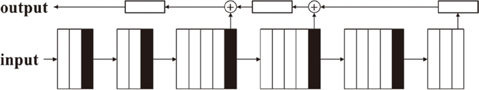
The experiments were implemented on NVidia Titan X Pascal, Intel® Core™ i7-7700K CPU and 32 GB RAM. To improve the accuracy of BIN recognition under given time and hardware memory constraints, FCN structures were analyzed through three simulations: 1) model depth, that is, the number of convolution layers, 2) transfer learning, and 3) dimension of the last three convolution layers. Here, the FCNs were trained with BINs written straight because rotated BINs were checked by the trained models. In addition, as the number of the paint-type BIN images was significantly larger than that of the sticker-type BIN images, all models were trained by 18272 images and validated by 8000 images of paint-type BINs. Four FCNs with deconvolution layers were first trained and validated (Table 1). Each FCN with deconvolution layers had four different depths. C a×a×b@d represents d convolution layers with a×a×b kernel and includes a rectified linear unit (ReLU) operation. A a×a denotes an a×a average pooling layer, and D a×a×b@d represents d deconvolution layers with a×a×b kernel. In Table 1, the input column is common and is applied from the top to the bottom layers. However, each output column is applied from the bottom to the top layers. The input of each deconvolution layer is either the layer’s output of the same row in the input column if it is the lowest deconvolution layer or is the pixel-wise sum of the outputs of the same row in the input column and the lower deconvolution layer in the same column. For example, Fig. 5 shows the structure of model D with output D. The models A–D were trained separately, and the validation results are shown in Fig. 6. Here, the recognition accuracy is the percentage of images in which all BIN characters were predicted correctly. The performance of the four models is summarized in Table 2. There is trade-off relation between recognition accuracy and computational complexity. Although 3144.6 s per epoch and 0.066 s per image were required to train and validate model D, it had the best recognition accuracy at 99.325%. In actual operation, average daily workload is approximately seven hundred images. Namely, model D recognizes two more images per a day than model A. one mis-recognition may occur accident and cost. Therefore, one more correct recognition is important. Furthermore, the given time for recognition is 3 s. The time for other processes such as data communication should be excluded. Thus, approximately 0.08 s could be used per image because rotated images should be recognized in real operation conditions.
Table 1. Four FCN structures.
NC denotes the number of the classes.
| FCN |
|---|
| Input | Output A | Output B | Output C | Output D |
|---|
| C 3×3×1@64 | | | | |
| C 3×3×64@64 | ↑ | ↑ | | |
| A 2×2 | D 4×4×64@35 | D 4×4×64@35 | | |
| C 3×3×64@128 | | | | |
| C 3×3×128@128 | | ↑ | ↑ | |
| A 2×2 | | D 4×4×128@64 | D 8×8×128@35 | |
| C 3×3×128@256 | | | | |
| C 3×3×256@256 | | | | |
| C 3×3×256@256 | ↑ | | | |
| C 3×3×256@256 | D 4×4×256@64 | | ↑ | ↑ |
| A 2×2 | | | D 4×4×256@128 | D 16×16×256@35 |
| C 3×3×256@512 | | | | |
| C 3×3×512@512 | | | | |
| C 3×3×512@512 | | ↑ | | |
| C 3×3×512@512 | | D 4×4×512@128 | | ↑ |
| A 2×2 | | | | D 4×4×512@256 |
| C 3×3×512@512 | | | | |
| C 3×3×512@512 | | | | |
| C 3×3×512@512 | | | ↑ | |
| C 3×3×512@512 | | | D 4×4×512@256 | |
| A 2×2 | | | | |
| C 7×7×512@512 | | | | |
| C 1×1×512@512 | | | | ↑ |
| C 1×1×512@NC | | | | D 4×4×NC@512 |
Table 2. Performance analysis for the FCN models.
| FCN models | Model A | Model B | Model C | Model D |
|---|
| Number of parameters | 2662499 | 11799715 | 22931811 | 37827299 |
Training time (s/epoch)
Validation time (s/image) | 1988.9
0.055 | 2684.4
0.064 | 2957.1
0.065 | 3144.6
0.066 |
Number of correct BIN recognition
BIN recognition accuracy (%) | 7921
99.0125 | 7936
99.2 | 7933
99.1625 | 7946
99.325 |
Although the initial values of the kernels were generated by the truncated normal distribution in the first simulation, the pre-trained model VGG 1920) was transferred as a set of initial values for the kernels of the first sixteen convolution layers in the second simulation. The pre-trained model was trained on the ImageNet ILSVRC data.20) This transfer learning was applied to the structure of model D, which achieved the best recognition accuracy in the above experiment. The validation results are shown in the Fig. 7. The recognition accuracy improved overall indeed increased to approximately 99.3875%.

Finally, simulations were performed for the more complex models as well as the transfer learning to improve recogniton accuracy. To extract more features, more kernels were adopted in the last three convolution layers. The last three convolution layers of model E were replaced with C 7×7×512@1024, C 1×1×1024@1024, and C 1×1×1024@35. Furthermore, those of model F consisted of C 7×7×512@1024, C 1×1×1024@2048, and C 1×1×2048@35. Figure 8 shows the validation results of additional models. Model F, which adopted transfer learning, achieved the best recognition accuracy, namely, 99.53333%. For model F, the train and validation time were about 3769.7 and 0.072 s, respectively. Therefore, model F was chosen owing to high recognition accuracy under operation time and hardware memory constraints.
3.2. Data Augmentation for Sticker-type BIN
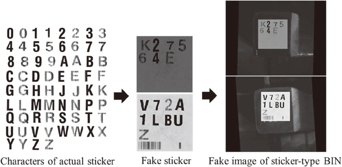
2415 images of sticker-type BINs were obtained during 36 operation days. In the training process for sticker-type BINs, a major problem was that the number of images was excessively small, as seen in Table 3. Certain characters never occurred during the two-year period of operation in which images are guaranteed to be stored on the server; however, it is possible that they may occur at some point. Therefore, the images of sticker-type BINs were reproduced by using actual stickers (Fig. 9). By randomly applying scaling, translation, and rotation at fine angles, fake stickers were reproduced from characters of actual stickers. Then the fake images were obtained by replacing the original stickers with the fake stickers and adding Gaussian distributed noise at the positions of the original stickers. The 2415 images of sticker-type BINs were separated into a training set of 1215 images and a validation set of 1200 images. To validate effect of data augmentation, 16000 fake images were generated and used to train model F. The validation results for the fake image are shown in the Fig. 10. The recognition accuracy increased from 98.6667% to 99.5% when data augmentation was used.
Table 3. Number of occurrences for each character in the data set of sticker-type BINs, where
Ch. and
Co. are abbreviations of character type and count, respectively.
| Ch. | 1 | 2 | 3 | 4 | 5 | 6 | 7 | 8 | 9 | 0 | A | B | C | D | E | F | G |
|---|
| Co. | 1702 | 2415 | 1784 | 1458 | 546 | 375 | 415 | 550 | 1473 | 2865 | 4 | 25 | 0 | 9 | 18 | 447 | 9 |
| Ch. | H | J | K | L | M | N | P | Q | R | S | T | U | V | W | X | Y | Z |
|---|
| Co. | 120 | 18 | 1007 | 10 | 8 | 16 | 68 | 392 | 1359 | 335 | 1 | 0 | 0 | 112 | 0 | 0 | 852 |
Finally, the proposed BIN recognition system was implemented in actual operation. Based on the simulations, the structure of the FCN with deconvolution layer was chosen as model F, and the initial values of the kernel weights were transferred from pre-trained weights of VGG19. In addition, the models that achieved the best recognition accuracy in the validation sets of paint-type and sticker-type BINs, were used as FCN for Paint and FCN for Sticker in Fig. 3. Furthermore, to improve recognition accuracy, information on BIN structure, namely, the order in which characters appear was used. Table 4 shows the BIN recognition results for eight days. The proposed system matched 6050 BINs from 6075 images; thus, the recognition accuracy was 99.58848%.
Table 4. Recognition accuracy of the proposed system. “Image” is the number of images processed for a particular day, and “Correct” is the number of correctly estimated images.
| Day | Image | Correct | Recognition
Accuracy (%) |
|---|
| 1 | 765 | 760 | 99.34641 |
| 2 | 743 | 742 | 99.86541 |
| 3 | 666 | 665 | 99.84985 |
| 4 | 772 | 770 | 99.74093 |
| 5 | 824 | 823 | 99.87864 |
| 6 | 765 | 761 | 99.47712 |
| 7 | 812 | 805 | 99.13793 |
| 8 | 728 | 724 | 99.45055 |
| Total | 6075 | 6050 | 99.58848 |
4. Conclusion
An end-to-end BIN recognition system was proposed for factory automation. There are paint-type and sticker-type BINs consisting of alphanumeric characters with the exception of I and O. In addition, the BIN may be rotated. To recognize these BINs, a fully convolutional network (FCN) with deconvolution layer was used. Futhermore, interpretation and sticker extraction modules were developed. To compensate for the small number of sticker-type BINs, data augmentation was performed by using fake images. In addition, to achieve high recognition accuracy under time constraints, various network structures and transfer learning processes were simulated. The proposed end-to-end BIN recognition system estimated BINs with an accuracy of approximately 99.59% in an eight-day period.
References
- 1) M. Chu, A. Wang, R. Gong and M. Sha: ISIJ Int., 54 (2014), 1638.
- 2) Y. Saito, T. Kanai, D. Igawa, Y. Miyamoto, S. Matsuo, Y. Matsushita, H. Aoki, S. Nomura, H. Hayashizaki and S. Miyashita: ISIJ Int., 54 (2014), 2512.
- 3) Y. Jeon, D. Choi, J. P. Yun and S. W. Kim: ISIJ Int., 55 (2015), 1942.
- 4) S. Zhou, Y. Chen, D. Zhang, J. Xie and Y. Zhou: ISIJ Int., 57 (2017), 123.
- 5) K. Agarwal and R. Shivpuri: J. Intell. Manuf., 25 (2014), 1289.
- 6) R. Zhang, S. Cheng and C. Guo: ISIJ Int., 58 (2018), 244.
- 7) S. Choi, J. P. Yun and S. W. Kim: Opt. Eng., 48 (2009), 037206.
- 8) S. Choi, J. P. Yun, K. Koo and S. W. Kim: Expert Syst. Appl., 39 (2012), 7621.
- 9) S. J. Lee and S. W. Kim: Expert Syst. Appl., 77 (2017), 34.
- 10) D. Kang, C. Park and S. Won: 34th Annual Conf. IEEE Industrial Electronics, IEEE, Piscataway, NJ, (2008), 1539.
- 11) H. Zao, Y. Wang, H. Hong and X. Zhang: 3rd Int. Conf. on Digital Manufacturing and Automation, IEEE, Piscataway, NJ, (2012), 112.
- 12) H. Hong, Z. Yu and X. Zhang: 3rd Int. Conf. on Digital Manufacturing and Automation, IEEE, Piscataway, NJ, (2012), 331.
- 13) S. Park and J. Lee: Int. Conf. on Hybrid Information Technology, IEEE, Piscataway, NJ, (2006), 287.
- 14) S. B. Shim, S. H. Choi and S. W. Kim: Int. Conf. on Control Automation and Systems, IEEE, Piscataway, NJ, (2010), 324.
- 15) Q. Zhao, P. Cao and D. Tu: Adv. Manuf., 2 (2014), 3.
- 16) S. J. Lee, J. P. Yun, G. Koo and S. W. Kim: Knowl.-based Syst., 132 (2017), 1.
- 17) S. J. Lee, W. Kwon, G. Koo, H. Choi and S. W. Kim: ISIJ Int., 58 (2018), 696.
- 18) J. Long, E. Shelhamer and T. Darrell: Proc. IEEE Conf. on Computer Vision and Pattern Recognition, IEEE, New York, (2015), 3431.
- 19) N. Otsu: IEEE Trans. Syst. Man Cybern., 9 (1979), 62.
- 20) K. Simonyan and A. Zisserman: arXiv:1409.1556, (2014), https://arxiv.org/abs/1409.1556, (accessed 2018-10-10).
- 21) C. B. Barber, D. P. Dobkin and H. Huhdanpaa: ACM Trans. Math. Softw., 22 (1996), 469.
- 22) S. J. Lee, S. W. Kim, G. Koo, W. Kwon and J. P. Yun: arXiv:1810.04029, (2018), https://arxiv.org/abs/1810.04029, (accessed 2018-10-10).