Casting and Solidification
Flow Instabilities in the Horizontal Single Belt Casting Process with an Inclined Feeding System
2019 年 59 巻 1 号 p. 69-75

詳細
2019 年 59 巻 1 号 p. 69-75
Both physical experiments and mathematical simulations were employed to investigate the transport phenomena involved during Horizontal Single Belt Casting (HSBC) of AA6111 aluminum alloy, using an inclined feeding system. Flow instabilities in the metal delivery system were first analyzed, and it was found that the first impingement gives rise to instabilities in the melt film falling from the slot nozzle of the head box. Meanwhile, this impingement also has the potential to result in air suction. Using the Eulerian multiphase method, the start casting stage is shown to be very short. Its predictions are similar to those from the Volume of Fluid (VOF) method, and both are confirmed by physical experiments. During steady state casting, one can classify the melt into four regions. The “wavy contour” in “Region I” is an instability largely induced by impingement on an inclined refractory piece. “Region II” demonstrates the buffer effect of the inclined refractory wall and the flow must be continuous within it. The resistance force induced by the melt that has flowed just earlier onto the belt, gives rise to “Region III”, which is a transition region. Its transient variations in width determine the quality of the strip’s edges. The thickness of “Region IV” is associated with both “Region II” and “Region III”.
There are two main reasons for researchers to focus on novel casting processes for metals. First, metals are one of the foundations of the modern industrialized world and will remain so in the future.1) Second, universities and all other research institutes have the responsibility to look for novel processes, in order to reduce operating costs and to pioneer energy and capital cost savings, so as to improve living conditions for humans in an environmentally friendly way. Fortunately, the Horizontal Single Belt Casting (HSBC) process2,3) has the potential to meet these requirements. HSBC for forming sheet metal products via a Near Net Shape Casting (NNSC) method was proposed over twenty years ago by researchers at McGill University,2) and at the University of Clausthal.3,4)
As a gravity driven process, the geometry of the feeding system determines the way in which the force of gravity acts in transferring the melt from a “tundish” onto a horizontal moving belt. This indicates that the design of this system plays an extremely important role. The goal in the design of the feeding system is to achieve an iso-kinetic distribution of the melt as it flows onto the belt. Thus, the basic principles for the design of the feeding system include two aspects:1) to decrease any instabilities induced as the liquid metal leaves the slot nozzle, in the most stable way,2) to decrease additional instabilities induced by the force of gravity during the transfer process between the slot nozzle and the horizontal, moving belt. Over the past twenty years, various feeding systems have been proposed and tested. At present, it is believed that the inclined feeding system shown in Fig. 1(a) is one possibility, owing to its good performance in pilot-scale tests at the McGill Metals Processing Centre (MMPC), at its Stinson, High Temperature Melting and Casting facilities, as shown in Fig. 1(b).

(a) Schematic view of an inclined liquid metal feeding system developed for the HSBC process. ht represents the melt depth within the “tundish”; (b) AA6111 strip cast by the HSBC pilot caster at the MMPC, with a width of 250 mm. (Online version in color.)
With the inclined feeding system shown in Fig. 1(a), there exists a clear melt-gas interface during the delivery process of metal. However, with physical experiments, the problem we are facing is the difficulty, or even impossibility, of prescribing values for all the physical properties, and phenomena, involved. Nonetheless, we need to know these details in order to guide the optimization of the current feeding system, and/or to design better feeding systems. Thus, numerical simulations are a good way to achieve this goal. The existence of the melt-gas interface makes the modeling process difficult and time consuming, in obtaining converged solutions. In the past several years, at least two mathematical models have been employed for solving such interfacial problems. They are the Phase Field method5) and the Volume of Fluid (VOF) method.6,7,8) As an industrial process, there are various features and several kinds of complicated transport phenomena co-existing. These include 1) the meniscus behavior, where the metal, air and moving cooling substrate co-exist; 2) shrinkage of the falling films driven by the forces of gravity and surface tension; 3) potential suction of the gas phase into the melt; 4) impingement between the melt film and flow obstacles, etc. It is very hard for us to evaluate the effectiveness of the design of any given feeding system and to understand the basic transport phenomena involved by using just one multiphase mathematical model, or just one simulation. A combination of the results of several different mathematical models are needed, so we can have a clearer, overall picture, of the possible transport phenomena involved in the HSBC process.
In the present paper, a two-dimensional mathematical model was first established, based on the Eulerian multiphase method. The resulting numerical predictions are compared using both the Phase Field method5) and the VOF methods,6,7,8) adopted by previous co-workers to evaluate the HSBC process. Then experiments were carried out on the HSBC pilot scale caster, in order to complement and validate simulated results.
The goal in the design of a feeding system for the HSBC, is to achieve the iso-kinetic distribution of the melt onto the horizontal moving belt.9) The transfer process of melt from a headbox onto the horizontal moving belt occurs very locally, during which solidification can be ignored.8) Thus, heat transfer is not critical to the current Eulerian multiphase model. With the current feeding system, there are two fluid phases, air and liquid metal. A Eulerian treatment is used for each phase. The description of the air-melt flow as interpenetrating continua incorporates the concept of phasic volume fractions, denoted by αq. The volume of phase q, (Vq), is defined by
| (1) |
The momentum balance for phase q is described by Eq. (2).
| (2) |
| (3) |
| (4) |
| (5) |
The RSM (Reynolds Stress Model) recommended by ANSYS FLUENT10) was used to describe the fluid flow.10) The stress term of phase q is described as
| (6) |
The individual Reynolds stresses
Figure 2 depicts the two-dimensional simulation domain, part of the boundary conditions and the structured mesh grid system used. The phenomena discussed in the present paper were analyzed in two dimensions, because 1) the feeding system geometry determines that there is no obvious mass or energy exchange across the strip width direction, except in the edge regions; 2) the fluid flow near the edge region can be well described by our physical experiments; 3) a three-dimensional simulation is time consuming due to the very fine mesh grids (10−4 m) that must be employed. The inlet velocity magnitude (uin) for the mixture phase was fixed to be 1.0 m/s, and its direction is normal to the inlet boundary. The speed of the horizontal belt (ubelt) was set to be 0.5 m/s, smaller than that of the inlet, so as to obtain a desired strip thickness. The initial solution for the governing equations is that, at t = 0, all the physical quantities are set to be zero. The convergence criterion for all simulations was set, such that all residuals reached 10−4, for all calculated variables. With regard to the accuracy and mesh grid independence, 2.9 × 10⁴ structured mesh grids were used over the entire simulation domain. The phase coupled SIMPLE algorithm was used when dealing with the pressure-velocity coupling. The chemical composition of AA6111 aluminum alloy, casting parameters, and related physical properties can be found in Tables 1, 2, 3.6,7)

Two dimensional simulation domain, boundary conditions and structured mesh grid system. The inclined angle (θ) is 45 degree. The backwall gap thickness is 0.5 mm and the slot width is 2 mm. (Online version in color.)
| Element | Al | Cu | Fe | Mg | Mn | Si | Ti | Zn |
|---|---|---|---|---|---|---|---|---|
| AA6111 | Rem. | 0.790 | 0.177 | 0.879 | 0.287 | 0.903 | 0.0001 | 0.0007 |
| Property, Symbol and Unit | Liquid Aluminum | Air |
|---|---|---|
| Density, ρ (kg/m3) | 2300 | 1.225 |
| Viscosity, μl (kg/m/s) | 1.338 E-3 | 1.7894 E-5 |
| Solidus temperature (K) | 861.15 | – |
| Liquidus temperature (K) | 923.15 | – |
| Operating Parameters/Assumptions | Value/Assumption |
|---|---|
| Surface tension of melt in air (N/m) | 0.914 |
| Static contact angle between melt and refractory (degree) | 125 |
| Static contact angle between melt and substrate (degree) | 120 |
| Superheat of the melt in the real practice (K) | 10–20 |
| Casting speed (m/s) | 0.5 |
| Inlet velocity (m/s) | 1.0 |
In general, the instabilities in the HSBC process can be classified into two categories; one kind refers to those generated by inherent turbulence instabilities and are not discussed in this paper. These were simplified by using the Reynolds-averaged method. However, the other kind of instability occurs during the melt transfer process, driven by the forces of gravity and surface tension. We need to decrease the gravity instability to an acceptable level by using a suitable design in the geometry of the feeding system or by optimizing the casting parameters, or both, in order to achieve the goal of “iso-kinetic” feeding onto a moving belt.
According to the basic design of the inclined feeding system shown in Fig. 1(a), there are at least two phenomena that can give rise to additional instabilities: 1) interactions between the melt and solid, such as when the melt passes through the tundish slot nozzle, or when the falling melt impinges on the inclined refractory wall of the feeding system, and the final impingement of the melt onto the horizontal moving belt; and, 2) interactions between fluids, such as melt-gas interactions and melt-melt interactions. The melt-gas interactions occur where a melt-air interface exists, and this interaction can affect the deformation (shrinkage and expansion) of the melt falling film, causing gas entrapment, meniscus oscillation, and so on.
Figure 3 shows the instabilities (wavy contour) in the melt falling film when using an inclined feeding system. Figure 4 shows the modeling instabilities in the melt’s falling film. In previous publications,8,9) these instabilities in the melt falling film shown in Fig. 3 were regarded as emanating from turbulence within the tundish region. In Fig. 4, the predicted asymmetry and unstable melt falling film did not come from the tundish region, thanks to the simplified inlet boundary condition used. This asymmetry, and unstable melt film, indicates that the first impingement between the melt falling film and the inclined refractory of the feeding system gives rise to additional instabilities. This can be validated by simple experiments in our daily life, as shown in Fig. 5.12) In Fig. 5(a), without any obstacle, the falling water flow out of the faucet is stable. With the obstacle, (a stable finger), the water flow becomes unstable, as shown in Fig. 4(b), owing to buckling of the water film. The instability shown in both Figs. 4 and 5(b) did not arise from the tundish region, due to the simplified inlet boundary conditions used, nor from the “faucet”. In other words, instabilities in the HSBC can be transmitted in a reverse flow direction. This means that efforts to optimize the design of tundishes, and slot nozzles, cannot preclude this kind of instability.
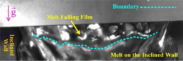
Instabilities during the melt falling process. (Online version in color.)
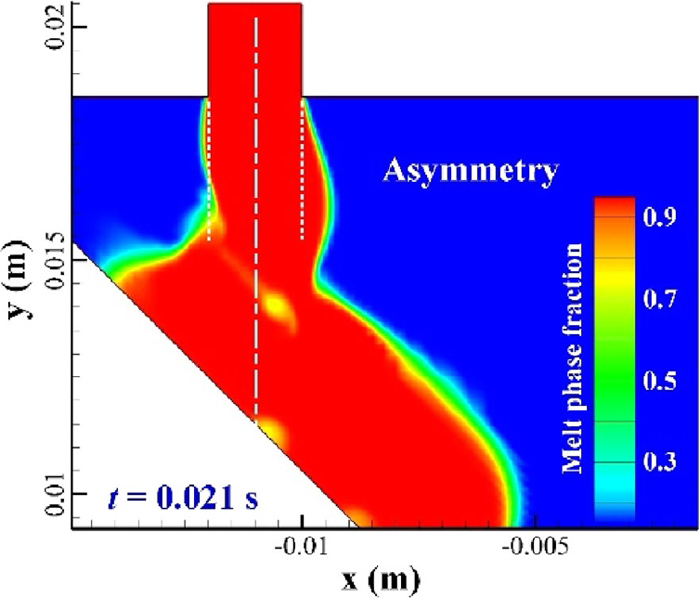
Asymmetry melt falling film induced by the impingement. (Online version in color.)

From the observations above, we know that the impingement between the liquid metal and obstacle can give rise to additional instabilities, and this is not good, if we are to realize the goal of “iso-kinetic” feeding of metal onto the belt. With the current inclined feeding system, there exist two such impingements; one impingement is between the melt falling film and the inclined refractory wall, and the other, is between the melt film and the moving horizontal belt.
3.2.1. The First ImpingementIn Fig. 6, the main melt stream impinges on the inclined wall of the feeding system, and splits into two streams. One stream moves upwards along the inclined surface, while the other flow moves downwards, to finally impact the horizontal moving belt. Owing to the force of gravity, the upward stream finally reverses downwards, gives rise to a backflow. The upward stream together with its backflow, forms a vortex, the center of which is not fixed. In Fig. 6(a), the coordinates of the vortex centre are (−0.117, 0.0133), while in Fig. 6(b) the coordinates of the vortex centre are (−0.118, 0.0140). When the upward stream returns downwards, it will partly merge with the melt falling film from the tundish slot, to become integrated into the main stream, impinging on the inclined wall. As such, there exists interactions between the melt falling film and the unstable vortex. These interactions raise the possibility of air suction, as shown in Fig. 7, which illustrates air suction during the period of the first impingement between the melt falling film and the inclined wall. The entrapped air phase can then be carried by the downward stream along the inclined surface and finally become a defect within the cast strip.
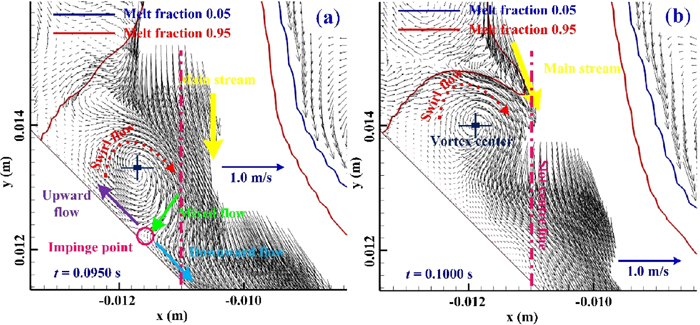
Velocity vectors distribution in the region of the first impingement, and the velocity magnitude (

Air suction at the position of the first impingement between the melt falling film and the inclined wall of the feeding system. Melt volume fractions larger than 0.95 and less than 0.05 were blanked to provide a clearer view. (Online version in color.)
In addition, in Fig. 6, it can also be seen that when the vortex moves upward, there exists a more obvious deformation in the melt falling film. This means that the stronger kinetic energy of the backflow of the upward stream will decrease the stability of the melt falling film.
3.2.2. The Second ImpingementThe first impingement is between the melt falling film and the inclined refractory wall. The target of this impingement is to decrease the kinetic energy of the melt falling film and to change its flow direction so as to make the second impingement less violent. As previously mentioned, during this process, no solidification occurs due to the thermal properties of the refractory material. After the first impingement, we see that the force of gravity and the friction force of the inclined wall will reorganize the flow pattern of the downwards stream. Finally, the reorganized melt film impinges against the horizontal moving belt at an angle of 45 degrees (Fig. 2). Once the superheated melt touches the water-cooled belt, heat will be extracted and a solidified shell will begin to form. Using the Phase Field method,5) coworkers have found that the gap thickness, combined with the melt inlet velocity through the tundish slot nozzle and the belt’s speed, are all important in governing meniscus behavior. According to the VOF method,6,7,8) tiny air pockets can be found forming along the bottom strip surface on a bare substrate.
Figure 8 shows the monitored total pressure at Point 1#, for a data acquisition frequency of 1×10⁵ Hz. There, it can be seen that at the start of the casting process, this initial impingement between the melt reorganized by the inclined wall of the feeding system and the horizontal moving belt, gives rise to a large total pressure (around 3000 Pa gauge). This large total pressure gives rise to penetration of the liquid metal into the gap, as shown in Fig. 8(c). By using either the Phase Field method,5) or the VOF method,6,7) similar backflows were observed, demonstrating the efficiency of the current mathematical model. During the steady state casting process, the total pressure varies like a wave, which is the same as that predicted using the VOF method.8)
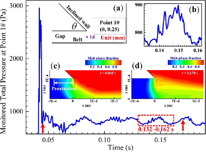
Predicted total pressure at Point 1#, at a data acquisition frequency of 1×10⁵ Hz: (a) the position of Point 1#; (b) a single pressure wave between 0.132–0.162 s; (c) meniscus status at t = 0.045 s; (d) meniscus status at t = 0.170 s. (Online version in color.)
This variable pressure distribution can significantly influence the air suction behavior at the meniscus. In Fig. 9, at the position of the second impingement between the melt and the horizontal moving belt, a thin air film is predicted to be sucked from the gap between the refractory wall and horizontal moving belt, as Fig. 9(c) shows. By contrast, the VOF method6,7,8) suggests that tiny air pockets can be found. In both cases, the VOF method and the current method show that there potentially exists a large heat resistance due to the meniscus behavior. From 0.132 to 0.162 s in both Figs. 8(b) and 9(b), we can see that the thickness of the air phase and the total pressure has the similar tendency. It indicates that there exists a strong relationship between the pressure and the thickness of the air phase film, which also suggests that pressure control in the HSBC process may be helpful.
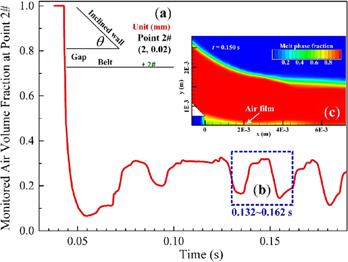
Predicted air volume fraction at Point 2#, at a data acquisition frequency of 1×10⁵ Hz: (a) the position of Point 2#; (b) a single wave between 0.132–0.162 s; (c) the air film distribution at t = 0.150 s. (Online version in color.)
In addition, at least in all the conventional continuous casting processes, the casting start period is of great importance. In the present paper, based on the Eulerian multiphase method, the simulated results shown in Figs. 8 and 9 strongly indicate that the casting start period in the HSBC process is very short, at least theoretically, if not practically. With the current inclined feeding system and related casting parameters, this stage is less than 0.1 s! This can be demonstrated by the physical experiments, as shown in Fig. 10, which illustrates the strip profile cast by the pilot caster. In Fig. 10(a), it can be seen that there exists a short round tip of liquid metal, which gradually enlarges into a strip of a similar width to the width of the slot nozzle.
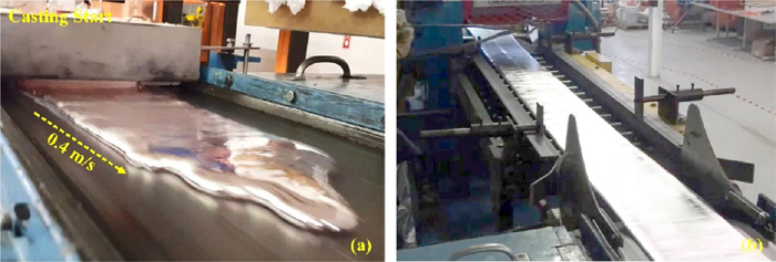
AA6111 strip profile produced by the pilot caster, with a casting speed of 0.4 m/s. The slot width is 250 mm: (a) view of upstream feeding system; (b) view of downstream pinch roll/mini-mill. (Online version in color.)
A design schematic of the pilot-scale HSBC caster can be found in References,7,14) but the experimental procedures14) are repeated here. Prior to casting, the entire metal delivery system, comprising the piston and the tundish system, is preheated using resistive heating systems. A graphite coating is applied to the top surface of the water-cooled belt. During the production of AA6111 alloy, approximately 130 kg of aluminum is first melted, and alloyed, in the induction furnace. The furnace is then transferred to the casting station, once the metallurgy is correct, the melt degassed, and grain refiner additions made. There, the melt is displaced upwards into the metal delivery system, by the downward motion of a piston into the furnace, delivering liquid metal at a pre-selected flow-rate. The displaced molten metal is then transferred through a tundish system, and delivered onto a textured steel belt. The metal subsequently solidifies into an as-cast strip, 1–10 mm thick, and 70–255 mm wide.
The short start period for initial casting is validated by the experimental results shown in Fig. 11. These depict the casting start period for the HSBC pilot caster. From this figure, it can be seen that the melt falling film is thicker at the edges, and that the width of the melt falling film becomes narrower from top to bottom (33.6 ms). The thicker edge and the narrow bottom indicate that there exists shrinkage along the width direction, especially near the edge region (thicker). This can also be seen from Fig. 12. When the melt falling film moves along the inclined wall (38.6–53.6 ms), the thicker edge becomes uniform due to the force of gravity, and the force of friction. This demonstrates that the inclined refractory wall of the feeding system gives rise to a buffer effect for the melt film after its first impingement. The thicker edge film spreads to both sides (48.6 ms), so as to extend the width of the melt film, then decrease the shrinkage along the width direction.

Casting start period using the inclined feeding system in the HSBC process. (Online version in color.)
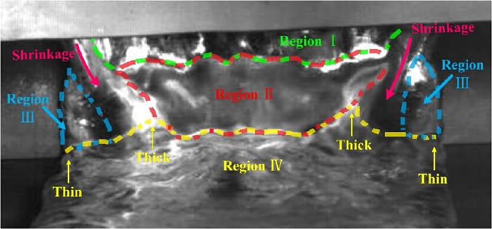
Steady casting.7) (Online version in color.)
Figure 12 depicts the details during the steady casting period. From this figure, it can be seen that there are four distinct regions. “Region I” is the melt falling film from the slot nozzle, and there exists a clear “wavy contour”. From Figs. 3 and 4, we can infer that this “wavy contour” could be partly induced by impingement between the melt falling film and the inclined refractory wall of the feeding system. Decreasing any instabilities in the tundish region will do little to avoid this “wavy contour”. “Region II” is the melt on the inclined refractory wall of the feeding system, which surface is smoother than “Region I”. The smoother surface demonstrates the buffer effect of the inclined refractory wall of the feeding system, and this effect can also be found from the experiments shown in Fig. 10. “Region III” is the transition region which does not exist before the second impingent occurs at the casting start period (given that at the casting start process, there is no resistance force, there exists a tip, as shown in Fig. 11), which is induced by the resistance force induced by “Region IV”. The variation of “Region III” determines the width of the edge region of the strip, as shown in Fig. 13. “Region IV” is the melt on the horizontal moving belt, which provides a continuous resistance force to both “Region II” and “Region III” to form the desired thickness and width of the strip. The magnitude of the resistance force induced by “Region IV” should be determined by the casting speed of the horizontal moving belt.

Variation of the strip width due to the resistance force induced by the previous melt onto the horizontal moving belt. The slot width is 100 mm, and the strip width d1 < d2 < d3. The speed of the horizontal belt (ubelt) was set to be smaller than that of the inlet (uin), so as to obtain a desired strip thickness. (Online version in color.)
The conclusions from this computational work can be summarized as follows:
(1) With the current mathematical model and the previous VOF method, the intrinsic “start period” is very short, and this has been adequately confirmed by experiments.
(2) After the first impingement between the incoming stream of liquid metal and the inclined wall of the feeding system, the melt stream diverges into an upwards stream and a downwards stream. The upward stream forms an unstable vortex due to the force of gravity and there are interactions between this vortex and the falling film of melt from the tundish slot nozzle. Air suction may occur due to these interactions.
(3) The initial impingement of the melt onto the inclined refractory wall of the feeding system, can give rise to instabilities. These instabilities decrease the stability of both the melt falling film and the downward stream, and finally give rise to the “wavy contour” of “Region IV”. The instabilities induced by the first impingement may preclude further efforts to decrease instabilities arising from initial flows from the tundish.
(4) The inclined refractory wall of the feeding system creates a buffer effect, making the thickness of the melt film more uniform. It can also decrease the shrinkage along the width direction.
(5) The melt on the horizontal moving belt, gives rise to a resistive force on the melt on the inclined refractory wall.
(6) With the inclined feeding system, there exist two technical difficulties: one is the control of the meniscus. The other, is the control of the “yellow line” in Fig. 13. i.e., the boundary between the melt on the inclined wall and the melt on the moving belt.
The authors would like to acknowledge the financial support received from the Natural Sciences and Engineering Research Council of Canada (NSERC), and the International Advisory Board of supporting companies of the McGill Metals Processing Centre (MMPC) in carrying out this research. The authors would also like to acknowledge the support in software licensing received from ANSYS Inc. to facilitate this research.