Abstract
Soft magnetic powder compacts can suppress eddy current loss compared to conventional laminated cores. However, the compacts accompany greater hysteresis losses because the easy magnetization axes are not controlled in powders. In this study, a novel soft magnetic compact was prepared from a platelet-shaped iron powder with well-controlled easy magnetization axes and its effects on magnetic properties and crystal orientation of the compact were investigated. Such platelet iron powder was produced using a ball-milling process. During milling, the iron powder was subjected to the deformation, resulting in the shape change to the platelet. Simultaneously, a (001) fiber texture was formed preferentially, as it is characteristic of the deformed bcc metal. The powder was then compacted into a toroidal shape. The platelet surface of the powder was oriented so as to become parallel to the toroidal direction. Consequently, the easy magnetization axis, which lies along the platelet surface, was also oriented to the toroidal direction. The toroidal compact prepared in this way exhibited excellent magnetic properties. For example, the permeability was approximately 2.4 times higher than that of the compact prepared from a conventional iron powder.
1. Introduction
Toroidal-shaped laminated cores comprising stacked low-carbon silicon steel with less than 1 mm in thickness are commonly used for magnetic cores in motors, generators, and other electromagnetic parts.1) A texture with the (001) plane parallel to the surface of the steel sheet maximizes the number of [001] easy magnetization axes in the sheet plane. Thus, this texture is ideal for the magnetic cores of rotating machines, in which magnetic flux travels along multiple directions in parallel cross section toward toroidal direction, which is a long way around the torus.2) Cores surrounded by wound copper wire that is powered by alternating electric current are subject to the eddy current, which causes power loss in the core.3) Dust cores, which are fabricated by compacting insulated soft magnetic powders, provide an advantage over laminated cores by suppressing eddy current loss. The suppression of eddy current loss results from the three-dimensional insulation of the powder, which segments the eddy current-producing region, unlike in electrical steel sheets.3) However, hysteresis loss is larger in dust cores than in laminated cores because the easy magnetization axes in powders are not controlled. Therefore, to reduce hysteresis loss in dust cores, it is necessary to control the easy magnetization axes in powders.
Using a conventional ball milling with the addition of graphite particles into iron particle, we obtained platelet-shaped iron particles in which the easy magnetization axes is oriented to the platelet surface.4) During milling, the shape of the iron particles changed from granular to platelet as a result of the repeated compression and ball rolling in the direction perpendicular to the platelet surface. Simultaneously, a (001) fiber texture was formed. When a platelet particle is placed on a flat surface, it spontaneously falls down in such a way that the platelet surface lies parallel to the flat surface. Similarly, when a platelet powder is placed into a die to form a toroidal compact, the platelet surface is expected to lie parallel to the underside of the die (i.e., parallel to the toroidal direction). When a platelet powder with the (001) texture is used as the raw material for the toroidal compact, the easy magnetization axis and platelet surface in the core will both be parallel to the toroidal direction. As a result of this geometric relationship between the toroidal compact and easy magnetization axis, the magnetic flux generated by current flowing through copper wound around the compact travels along the easy magnetization axis. Therefore, a platelet powder with (001) fiber texture is ideal for magnetic cores in which magnetic flux travels along multiple directions in parallel cross section toward toroidal direction.
In this paper, powder compacts were prepared using three types of iron powders: conventional water-atomized iron powder; platelet iron powder milled without lubrication, which has a weak (001) texture; and platelet iron powder milled with lubrication, which has a strong (001) texture. The compacts formed from the three powder types were compared with each other to elucidate the effects of the (001) texture of the platelet iron powder on the magnetic properties and crystal orientation of the powder compact.
2. Experimental
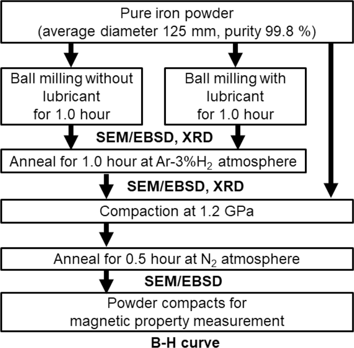
A flow chart summarizing the overall experimental procedure and characterizations is shown in Fig. 1. Water-atomized iron powder (ML35N, Kobe Steel, Ltd. purity with more than 99.8%) was processed by ball milling. The iron powder with 5 g in weight was placed in a stainless steel vessel and 20 steel balls (AISI 52100, diameter = 9.52 mm) and oil (20 ml) (KURE Engineering Co., Ltd., 5-56) were added as the milling medium and lubricant, respectively. For comparison, another 5 g of iron powder was also milled without lubricant. The vessel was mounted on a centrifugal ball mill (Nisshin Giken Co., Ltd., NEV-MA-8) and swung at 59.1 rad/s for 1.0 h. The resultant powders and the iron powder before milling were annealed using a tube electric furnace (TMF-500N, ASONE, Japan) under Ar-3%H2 atmosphere for 1 h. The annealed powders were compacted at 1.2 GPa in a tungsten carbide die and then annealed at 550°C under N2 atmosphere for 0.5 h.
The morphologies and crystallographic textures of the resultant powders and toroidal compacts were characterized by field-emission scanning electron microscopy (FE-SEM; JIB-4600F, JEOL Co., Ltd.), electron backscattered diffraction (EBSD; OIM of EDAX/TSL), and X-ray diffraction (XRD; Rigaku Smart Lab X-ray diffractometer). The acceleration voltage and working distance during SEM-EBSD were 15 kV and 15 mm, respectively. The scan step size when acquiring EBSD measurement was 1.3 μm on a hexagonal scan grid. Prior to SEM-EBSD observations, the particles and powder compacts were embedded in Technovit 5000 conductive resin (Kulzer Co., Ltd.,) in a stub shaped mold and mechanically polished using emery paper and diamond paste. Finally, to remove any residual near-surface deformation and eliminate any artifacts introduced by sample preparation, Ar ion milling was performed using an ion milling system (IM4000, Hitachi Co., Ltd.). After SEM-EBSD observation, the EBSD data were processed using TSL OIM analysis 7 software (TSL Co., Ltd.). The cross sections of the particle were also observed by SEM. Based on a logarithmic strain used to evaluate the amount of plastic strain on a compressed rod, the amount of plastic deformation of a milled particle was evaluated by Eq. (1):
where
ε is the strain,
T is the average thickness of the platelet powder, and
Di is the average diameter of 50 iron particles before milling. The XRD patterns and pole figures were obtained using a Ni-filtered Cu-K
α radiation (1.542 Å). Pole figure measurements were performed using an in-plane measurement method.
5) Based on the (011), (002), and (211) pole figures, the orientation distribution function (ODF) was calculated using the method of Dahms and Bunge.
6) The main components of the obtained textures were evaluated by examining the IPF derived using the ODF software. The XRD data were processed using “Standard ODF” software (Norm Engineering Co., Ltd.).
The dimensions and weights of the toroidal compacts were measured to derive the compact density using a micrometer and electrical balance. The magnetic properties of the powder compacts were also evaluated. Copper wires as excitation and search coil were wound around the toroidal cores 400 turns and 25 turns, respectively. Using a DC–AC magnetization analyzer (MTR-2937, Metron Co., Ltd.), direct-current hysteresis loops were obtained under a maximum applied magnetic field of 10000 A/m. The maximum permeability, magnetic flux, coercive force, and iron loss of the toroidal cores were then obtained from the hysteresis loops.
3. Result and Discussion
3.1. Powder Preparation and Characterization of the Crystallographic Orientation
Figure 2 displays typical SEM images [(a-1) to (a-3)] and cross-sectional images [(b-1) to (b-3)] of iron powders milled with lubricant for 0 h [(a-1) and (b-1)], 0.10 h [(a-2) and (b-2)], and 1.00 h [(a-3) and (b-3)]. The iron particles before milling exhibited spherical shapes and changed into platelet shape as shown in Figs. 2(a-1) and 2(a-2). As the milling time increases, the iron powder plastically deformed more severely, as shown in Fig. 2(a-3). The iron powder milled without lubricant showed the same trends. The thickness of a platelet particle milled for 1.00 h [Fig. 2(b-3)] was approximately 3 μm, and the average diameter of the iron particle before milling was 125 μm. Therefore, the logarithmic strain of a platelet particle was about −3.7 following Eq. (1).

Figures 3(a) and 3(b) show the XRD patterns of the iron powders milled with and without lubricant, respectively. Their patterns were measured by changing milling times. All diffraction peaks were assigned to α-iron phases. The relative intensities of the diffraction peaks of iron powder before milling were similar to those of polycrystalline α-iron (Joint Committee on Powder Diffraction Standards card no. 01-071-3763), indicating that the iron powder had no preferred orientation before milling. For the powders milled without lubricant, the relative intensity of the (002) and (110) Bragg reflections changed slightly with milling time, which implies the formation of a weak texture in the platelet powders. In contrast, for the powders milled with lubricant, the intensity of the (002) Bragg reflection increased obviously with milling time, whereas that of the (110) reflection decreased. The XRD patterns of the iron powders milled with lubricant indicates that a strong texture was formed during milling. The powder milled for 1.00 h was employed for further investigation.
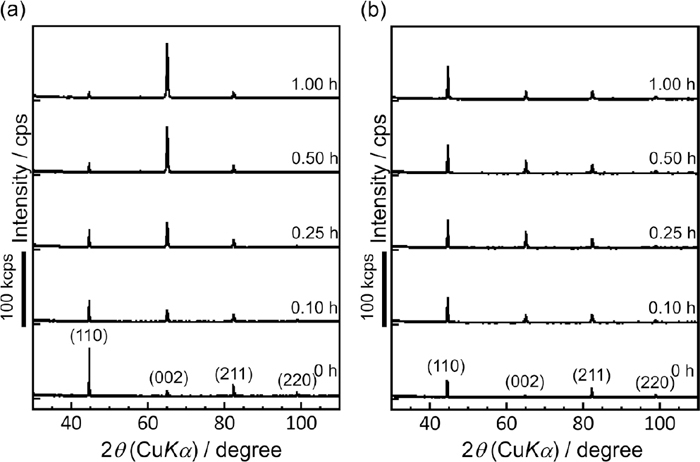
Figure 4 shows typical SEM images [(a-1) to (c-1)] and IPF maps along the directions normal [(a-2) to (c-2)] and in-plane [(a-3) to (c-3)] with respect to the platelet surface of the iron particles before milling [(a-1) to (a-3)], after milling for 1.0 h without lubricant [(b-1) to (b-3)], and with lubricant [(c-1) to (c-3)]. The schematics shown in the lower left portions of IPF maps indicate the coordinate system on a sample particle. The fine particles with the sizes of a few micrometers locating around the iron particles in the center of the SEM images are copper particles which are contained in the conductive resin used for SEM observation. As shown in Figs. 4(a-2) and 4(a-3), the grain boundaries of iron particles before milling were obvious and the individual grains were uniformly colored; these findings indicate that the grains contained almost no dislocation. Figures 4(b-2) and 4(c-2) show the IPF maps of particles milled without and with lubricant along a direction normal to the platelet surface, respectively. Various orientations are developed within the original grains after milling without lubricant. On the platelet surface of the particle milled without lubricant, the regions corresponding to the (001) planes (red region) and (111) planes (blue region) were slightly expanded over the grain [Fig. 4(b-2)]. In contrast, almost all of the area on the platelet surface of the particle milled with lubricant was dominated by the (001) and (111) planes, and the (001) region was larger than the (111) region [Fig. 4(c-2)]. Figures 4(a-3) and 4(b-3) show the IPF maps of particles milled without and with lubricant along a direction in-plane with respect to the platelet surface, respectively. No strong crystallographic orientation was observed in the IPF maps of particles milled without lubricant [Fig. 4(b-3)]. In contrast, the (001) and (101) planes and their intermediate planes were observed in the IPF maps of particles milled with lubricant [Fig. 4(c-3)]. The formation of a preferred orientation in the particles milled with lubricant is discussed in the next paragraph.
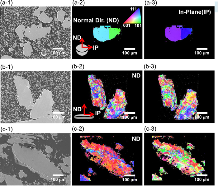
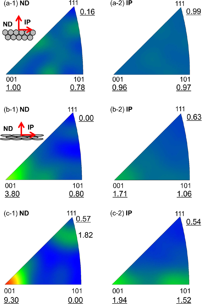
Figure 5 shows a set of IPFs along the directions normal [(a-1) to (c-1)] and in-plane [(a-2) to (c-2)] for the iron powder before milling [(a-1) and (a-2)], after milling for 1 h without lubricant [(b-1) and (b-2)], and with lubricant [(c-1) and (c-2)]. The underlined values in Fig. 5 indicate the pole density of each plane. The inset in the upper left portion of each IPF shows a schematic of the sample coordinate system of the powder in the sample holder for the XRD measurement. When the sample powder was placed in the well of the glass holder for the XRD measurement, the particles became oriented because the platelet surface spontaneously becomes parallel to the underside of the holder well. Consequently, the IPFs were roughly the same as those obtained at the directions normal to and in-plane with respect to the platelet surfaces of the iron powders. Figures 5(a-1) and 5(a-2) show the IPFs of unmilled powder along the normal direction (shown as “ND” in the figure) and the in-plane direction (shown as “IP” in the figure), respectively. The maps indicate a low-pole density of approximately 1 at all parts of IPFs, indicating that the powder before milling did not have a preferred orientation. As mentioned above, the relative intensities of XRD peaks for the iron powder without milling (Fig. 3) were similar to those for polycrystalline α-iron. Thus, a certain amount of variation in pole density in IPFs as shown in Figs. 5(a-1) and 5(a-2) was unavoidable in the present measurement. In IPFs of the milled powders without and with lubricant along the normal direction [Figs. 5(b-1) and 5(c-1)], the pole densities around (001) were slightly higher and higher than that in the IPF of the powder without milling, respectively. In the IPFs along the in-plane direction [Figs. 5(b-2) and 5(c-2)], the pole density around a side connecting (001) and (101) was high. As the crystal faces of (uv0) are perpendicular to (001), which strongly orients toward the direction normal to the particle surfaces, this correspondence between the IPFs along the normal and in-plane directions is logical. In addition, the pole density around (111) is relatively high (1.82) as shown in Fig. 5(c-1) for the powder milled with lubricant. Thus, slightly strong and strong (001) + (111) double-fiber texture was formed during milling without and with lubricant, respectively.
As mentioned above, the powders were plastically deformed from spherical particles to platelet-shape particles by forces exerted by the milling medium (Fig. 2). The deformation progressed by the repeated compressive stress generated by the balls compressing and rolling in a normal direction to the platelet surface. As a result, a (001) + (111) double-fiber texture was formed. The texture formed by plastic deformation is affected not only by the processing mode (e.g. uniaxial compression, rolling, and twisting) but also the lubricant condition. Friction between the material surface and tool (roll for rolling, die for uniaxial compression, etc.) induces a shear force accompanied by shear textures localized near the material surface, and then, through-thickness variations of texture are formed.7) Therefore, the texture of the platelet powder milled without lubricant was less oriented than the powder milled with lubricant. A detailed formation process of the texture in the powder milled with lubricant is also described in our previous report.4)
The (001) + (111) double-fiber texture most likely caused by the characteristic of bcc metals. Dillamore et al., conducted a quantitative study of textures, which were developed in uniaxially compressed iron-0.02%C cylinder, and pole densities of the compressed sample around (001), (101), and (111) were 8.9, 0.1, and 8.0, respectively.8) The appearance of the texture, which indicates low-pole density around (101) and high pole density around (001) and (111), share similarity with the present case. On the contrary, there is a difference between the ratio of the pole densities around (001) to that around (111) of the materials: the ratio of the present material is higher than that of the uniaxially compressed iron-0.02%C cylinder. The feature of the texture of the present case is favorable for the magnetic cores.
3.2. Effect of Thermal Treatment on the Crystallographic Texture in Iron Powder
Figure 6 shows a set of IPF maps along the directions normal to the cross section or platelet surfaces of the iron particles annealed at 550°C [(a-1) to (c-1)] and 600°C [(a-2) to (c-2)] before milling [(a-1) and (a-2)], after milling for 1.00 h without lubricant [(b-1) and (b-2)], and after milling for 1 h with lubricant [(c-1) and (c-2)]. Figures 6(a-1) and 6(a-2) show IPF maps of the unmilled iron powders annealed at 550°C and 600°C, respectively. As similar to the powders before annealing, both annealed powders had crystal grains of 100–200 μm in size and kept distinct grain boundaries. Figure 6(b-1) shows the IPF map of the iron powder milled without lubricant and annealed at 550°C. Some of the crystal grains were several tens of micrometers smaller than the original grains, and the individual grains were uniformly colored, indicating that recrystallization takes place in it. But there was still the number of grains with indistinct grain boundaries and gradual variations in color in the milled powder by annealing at 550°C, indicating that the recrystallization process was still incomplete. In contrast, whole grains in particles annealed at 600°C [Fig. 6(b-2)] were uniformly colored, indicating recrystallization process was complete. Figures 6(c-1) and 6(c-2) show the IPF maps of the iron particles milled with lubricant and annealed at 550°C and 600°C, respectively. The planes of (001) (red region) and (111) (blue region) were dominant in the particles annealed at 550°C, and their boundaries were indistinct [Fig. 6(c-1)]. In contrast to this, the particles annealed at 600°C [Fig. 6(c-2)] exhibited distinct grain boundaries, indicating that the recrystallization was complete, and the (001) and (111) planes were no longer dominant in the entire particle.
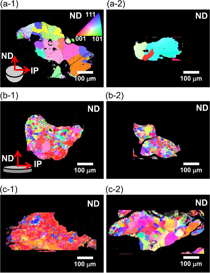
Figure 7 shows a set of IPFs derived from ODF at directions normal to the glass sample holder for XRD measurements of the powders annealed at 550°C and 600°C. Figures 7(b-1) and 7(b-2) show the IPFs of the powders milled without lubricant and annealed at 550°C and 600°C, respectively. The pole density around (001) in the IPF increased slightly from 3.80 to 4.23 by annealing at 550°C. However, the pole density around (001) of the milled powder annealed at 600°C decreased to 3.75. Figures 7(c-1) and 7(c-2) show the IPFs of the powders milled with lubricant and annealed at 550°C and 600°C, respectively. The pole density around (001) in the IPF increased slightly from 9.30 to 9.81 by annealing at 550°C and decreased to 6.76 by annealing at 600°C. Dislocations introduced into the metal powder during milling interact with each other and formed a three-dimensional cell structure and the cell structure changes to subgrains during annealing. The stored energy of the subgrains is still larger than the energy of fully recrystallized grains, so that the high-temperature annealing leads to subgrain rotation to reduce the stored energy.9) Although the mechanisms still remains unclear, it was reported that the mean subgrain misorientation changes depending on the orientation gradient introduced by deformation prior to annealing.9) We speculated that the changes in the mean subgrain misorientation during recovery increases in the pole density in the IPF of powders annealed at 550°C. Even after recrystallization, the (001) fiber textures were largely retained, as shown in Figs. 7(b-2) and 7(c-2). Although the mechanism is still not clear, in bcc metals, the deformation texture is largely retained in bcc metals.10) A more detailed study will be needed to understand the mechanism of the texture development during recovery and recrystallization. In addition, since the platelet powders are relatively thin with respect to the crystallite size, only either a single grain or a few grains are present in the thickness of the powder. The phenomena observed so far in bulk material in case when the ratio between the thickness and crystallite size is small may need to be reconsidered.11) However, this is beyond the scope of this paper as this paper mainly focus on the effects of the (001) fiber texture on the soft magnetic properties of powder compacts.

To reduce the coercive force in the powder compact, it is desirable to anneal the powders at the temperatures above 600°C, where the recrystallization occurs. This is because fully recrystallized grains contain few dislocations to cause domain wall pinning. As a result, the coercive force in fully recrystallized soft magnetic polycrystalline metals is reduced significantly.3) However, as shown in Fig. 7(c-1), the (001) fiber texture was most strongly developed in the powder annealed at 550°C. Therefore, in this paper to elucidate the effects of the (001) texture of the platelet iron powder on the magnetic properties and crystal orientation of the powder compact, the magnetic properties were investigated of compacts prepared from powders annealed at 550°C.
Table 1 shows the dimensions, weight, and density of each prepared compact. As might be expected, the core prepared from the milled powders showed the lower density because dislocations and additional grain boundaries, which inhibit plastic deformation, were introduced by milling.
Table 1. Dimensions, weights, and densities of the powder compacts.
| Outer dia.
[mm] | Inner dia.
[mm] | Thickness
[mm] | Weight
[g] | Density
[g/cm3] |
|---|
| Powder without milling | 45.08 | 32.99 | 4.77 | 26.94 | 7.62 |
| Milled without lubricant | 45.13 | 33.00 | 5.16 | 27.67 | 7.21 |
| Milled with lubricant | 45.11 | 32.98 | 4.96 | 27.27 | 7.38 |
Figures 8(a) and 8(b) show an image of the appearance and cross section of the compact prepared from the particles milled with lubricant, respectively. As shown in Fig. 8(b), the particle interfaces were oriented parallel to the upper and lower surfaces of the toroidal compact because the powders were arranged following the orientation of the compaction die. Therefore, the easy magnetization axis along the platelet surface was parallel to the toroidal direction. Because of this geometric relationship between the toroidal compact and the easy magnetization axis, the magnetic flux in the toroidal compact travels along the easy magnetization axis.

Figure 9 shows a cross-sectional SEM images, IPF map, and IPF along the vertical direction of the IPF map for each compact. The IPFs were obtained from recalculated EBSD data. The compact made of the unmilled powders exhibited granular interfaces [Figs. 9(a-1) and 9(a-2)] without any preferred orientation [Figs. 9(a-2) and 9(a-3)]. In the compact made of the powders milled without lubricant, the particle interfaces were stretched in the horizontal direction, following powder orientation parallel to the compact die [Figs. 9(b-1) and 9(b-2)], and very weak preferred orientation was observed [Fig. 9(b-3)]. The IPF map of the compact made of the powders milled with lubricant [Fig. 9(c-2)] was dominated by red color, which represents the (001) texture. The IPF shown in Fig. 9(c-3) also indicates strong pole density around (001). These results indicate the successful formation of the toroidal compact in which the easy magnetization axis lies in the toroidal direction.

Figure 10 shows the direct-current hysteresis loops of the compacts prepared from three powders, and Table 2 gives the magnetic properties determined from the hysteresis loops. Relative permeability increased in the following order: powder milled with lubricant > powder milled without lubricant > unmilled powder. The magnetic flux density was also maximized for the core prepared from the powder milled with lubricant, whereas the powder milled without lubricant resulted in the lowest magnetic flux density. As might be expected from the relation between the magnetic properties and the easy magnetization axis, the core with the highly developed (001) texture prepared from the powder milled with lubricant exhibited the highest relative permeability of 1285 and magnetic flux density of 1.72 T at 10 kA/m. On the contrary, the smallest coercive force was observed for the core prepared from unmilled powder because of its strain-free microstructure with larger grain, which was about half value of the milled powders. As the in-plane demagnetization factor for a platelet particle is close to zero, the permeability of the platelet particle is higher than that of a spherical particle. This phenomenon is known as magnetic shape anisotropy3) and causes a milled, flattened particle to have a higher permeability and magnetic flux density as compared to a spherical particle. Thus, the differences in permeability and magnetic flux density between the cores made of the unmilled spherical and the platelet powders milled without lubricant is attributed to the magnetic shape anisotropy. Also, the effects of the (001) fiber texture on the magnetic properties are well reflected in the differences in the permeability and the flux density between the cores made of the platelet powders milled with and without lubricant. The permeability and the flux density of the core prepared from powder milled with lubricant were, respectively, 180.7% and 3.6% greater than those of the core prepared from powder milled without lubricant. There are small differences in the packing density of the cores (7.21 g/cm3 and 7.38 g/cm3, respectively) as shown in Table 1. The effect of the density on permeability should be taken into account to reveal the effect of the (001) texture on permeability. Even a small void whose permeability is five orders of magnitude less than iron, significantly decrease a core’s permeability and the amount of void is inversely related to density. According to Takajyo,12) the permeability μ of a soft magnetic compact is calculated by Eq. (2):
|
μ=η
μ
0
(
μ
t
-
μ
0
)
/{N(1-η)(
μ
t
-
μ
0
)+
μ
0
}+
μ
0
,
| (2) |
where
η is the packing density of the compact,
N is the demagnetizing factor,
μt is the intrinsic permeability of the material, and
μ0 is the vacuum permeability. As mentioned above, the in-plane demagnetization factor,
N, for the platelet shape is close to zero. Then,
Eq. (2) can be simplified as
Eq. (3):
|
μ=η(
μ
t
-
μ
0
)+
μ
0
,
| (3) |
This indicates that
μ increases with the packing density. The packing densities for the powders milled without and with lubricant were estimated from the compact densities (
Table 1) to be 0.916 and 0.937, respectively. Thus, the difference in the densities between the compacts prepared from powders milled without and with lubricant had little contribution to the difference in the permeability. Additionally, as reported by Tomida,
2,13) 3% Si steel sheets with (001) fiber texture was prepared by using a special process of manganese removal and decarburization. Its permeability was approximately two times higher than that of conventional 3% Si non-texture steel sheets.
2) This is a similar improvement to the present case. Therefore, it is evident that the increase in the permeability in both cases is related closely to the (001) texture. Therefore, a magnetic compact with the (001) fiber texture was successfully prepared by the simple mechanical milling method, and the texture improved effectively the magnetic properties of the compact.
Table 2. Magnetic properties of compact prepared from powder before milling, milled without and with lubricant.
| Relative permeability μmax | Flux density B10k (T) | Coercive force Hc (A/m) |
|---|
| Powder without milling | 526 | 1.66 | 154 |
| Milled without lubricant | 711 | 1.56 | 337 |
| Milled with lubricant | 1285 | 1.72 | 271 |
4. Conclusion
Pure iron powders were milled with and without lubricant using a conventional ball mill. Under the both milling conditions, the shape of the iron powder changed from granules to platelets. Simultaneously, a (001) fiber texture was developed only in the powder milled with lubricant. To evaluate the effects of the (001) fiber texture on the magnetic properties of a compact, the powder annealed at 550°C was compacted into a toroidal shape and the direct-current hysteresis loops were obtained. In the die used to make the toroidal core, the platelet faces of the powder was set to be parallel to the underside of the die and also the toroidal direction. It was confirmed by the EBSD experiment that the easy magnetization axis of the powder with (001) texture were parallel to the toroidal direction. Consequently, we successfully produced a new toroidal compact in which the easy magnetization axis lies along the toroidal direction. This toroidal compact showed about 1.8 and 2.4 times larger permeability than the compacts prepared from non-oriented platelet powder or from conventional water-atomized iron powder. The improved permeability is attributed to the synergy effect of magneto-crystalline anisotropy and magnetic shape anisotropy. To the best of our knowledge, this is the first trial to make a toroidal compact from the iron powder with (001) fiber texture and to investigate its magnetic properties in a quantitative way. This new iron powder with (001) fiber texture is an ideal candidate for use of a magnetic compact in electromagnetic parts.
Acknowledgments
The authors thank S. Yanase and Y. Kyyoul for helpful discussions and are grateful to M. Miwa for providing technical assistance. This research was supported by the New Energy and Industrial Technology Development Organization (NEDO) along with a Grant-in-Aid for Young Scientists (B), 2017–2019 (17K14845, Satoshi Motozuka).
References
- 1) F. J. G. Landgraf: JOM, 64 (2012), 764.
- 2) T. Tomida: J. Appl. Phys., 79 (1996), 5443.
- 3) J. David: Introduction to Magnetism and Magnetic Materials, CRC Press, Boca Raton, (1998), 321.
- 4) S. Motozuka, T. Ikeda, T. Miyagawa, H. Sato and M. Morinaga: Powder Technol., 321 (2017), 9.
- 5) K. Nagao and E. Kagami: Rigaku J., 27 (2011), No. 2, 6.
- 6) M. Dahms and H. J. Bunge: J. Appl. Crystallogr., 22 (1989), 439.
- 7) J. F. Humphreys and M. Hatherly: Recrystallization and Related Annealing Phenomena, 2nd ed., ed. by J. F. Humphreys and M. Hatherly, Elsevier, Amsterdam, (2004), 80.
- 8) I. L. Dillamore, H. Katoh and K. Haslam: Texture, 1 (1974), 151.
- 9) J. F. Humphreys and M. Hatherly: Recrystallization and Related Annealing Phenomena, 2nd ed., ed. by J. F. Humphreys and M. Hatherly, Elsevier, Amsterdam, (2004), 169.
- 10) J. F. Humphreys and M. Hatherly: Recrystallization and Related Annealing Phenomena, 2nd ed., ed. by J. F. Humphreys and M. Hatherly, Elsevier, Amsterdam, (2004), 215.
- 11) P. J. M. Janssen, Th. H. de Keijser and M. G. D. Geers: Mater. Sci. Eng. A, 419 (2006), 238.
- 12) S. Takajyo and Y. Kiyota: J. Jpn. Soc. Powder Powder Metall., 32 (1985), 259 (in Japanese).
- 13) T. Tomida and T. Tanaka: ISIJ Int., 35 (1995), 548.
