2019 年 59 巻 7 号 p. 1295-1303
2019 年 59 巻 7 号 p. 1295-1303
Surface cracks or microcracks have been reported as one source of fatigue life deterioration. Propagation of microcracks into the steel substrate may appear on a deformed part when zinc-coated steels are used for direct hot press forming. This work investigated crack occurrence in galvanized steel sheets with coupled thermo-mechanical finite element simulations and realistic HPF experiments. This study used a two-dimensional hat-shaped tool called Conventional–Forming to effectively feature a cross-section of hot press formed parts in a vehicle. Microcracks occurred on the product wall-outside when the Conventional-Forming die moved vertically and the tool contacted the material. The depth of microcracks in the deformed zone where compressive-bending and unbending followed by a straightening occur is highly dependent on the magnitude of effective strain. Therefore, it is presumed that smaller magnitudes of effective strain from forming can reduce the microcrack depth on the workpiece. To identify ways to lower the effective strain, the study focused on the tool contact and bending curvature of the workpiece during forming. Consequently, Side-Forming, in which a material undergoes deformation behavior from a die entering from an oblique direction, was proposed. With other conditions unchanged, the numerical calculations and experimental results indicated a lowered effective strain and a subsequent significant reduction in microcrack depth. Moreover, the required qualities for hot formed products such as hardness and shape accuracy could be also achieved.
Hot press forming (HPF, also called “hot stamping”) with a quenchable boron steel is a currently well-known technology in the automotive industry, exhibiting improved formability at high temperature and ultra-high strength of 1.5 GPa after quenching.1) A material is heated to about 900°C in the furnace and transferred to a press in air. During the austenitization and transfer process, resistance to oxidation of the steel sheets is achieved with the application of protective surface treatment such as Al-based and Zn-based coatings.2) A heated material is deformed at high temperature and subsequently quenched in the cooled tool. There are two basic processes, defined as direct and indirect HPF. Pre-formed parts prepared by cold stamping are heated and calibrated in the hot stamping stage for the indirect HPF while flat sheets are originally used in the direct HPF.3) Irrespective of the HPF processes, a manganese-boron steel called 22MnB5 is considered a standard material since martensite is transformed from homogenous austenite at a critical cooling rate higher than 30°C/s.4,5)
Because of strict safety regulations, HPF technology has been widely adopted for crash resistant parts for both underbody and upperbody structures in passenger vehicles. Especially, components in the underbody structure can be affected by corrosion from exposure to wet environments. Therefore, there has been a growing interest in the application of zinc-coated materials with their cathodic protection.6) However, there have been reports of surface cracking that propagates into the steel substrate when this coating, such as galvanizing (GI), is used in direct HPF.6)
The studies associated with these surface defects of zinc-coated steels have identified two possible mechanisms, macrocrack due to Liquid Metal Embrittlement (LME) and microcrack occurring on deformation.7) The zinc coating layers in a galvanized steel consist of α–Fe(Zn) or (α–Fe(Zn) + Liquid Zn) phases since the zinc in the coating layers transforms to Fe–Zn alloys by inter-diffusion during heating.8) When the zinc contents exceed the range of solubility in α–Fe on Fe–Zn binary phase diagram, a liquid zinc phase exists on the top of a steel substrate. The grain boundaries of the base metal are susceptible to liquid metal penetration during deformation.9) This leads to severe cracks with depth generally greater than 50 μm.7) This LME mechanism can be controlled by extending the time for diffusion annealing.10) However, the longer heating time causes a decrease in productivity. On the other hand, Son et al. reported that LME can be prevented by introducing an inhibition layer between the Zn coating and steel substrate to promote faster Fe–Zn alloying during heating under typical process conditions such as temperature and dwell time.11)
Considering the microcrack formation, the fracture occurs at the solid α–Fe(Zn) grain boundary in the coating layer and propagates into the steel substrate when the material is deformed. Unlike LME, no assignment of Zn was found in the crack of a base metal and as an example these cracks up to 30 μm were observed for direct HPF experiment with a hat profile.12) To assess the effect of microcracks on product quality, a deterioration of fatigue life for hot stamped components has been reported when the microcrack depth is greater than 10 μm in the base metal.13) Therefore, some technology and research activities devoted to the development of a hot-formed component with a microcrack depth of less than 10 μm have been carried out. For example, the indirect HPF process reduces the severity and number of coating cracks because the shaping part geometry in the tool was completed in the cold stamping stages.14) In the direct HPF process, microcracks are also suppressed by introducing a forced-precooling stage between the furnace and press.15) However, the need of additional required resources and increased costs should be considered when considering practical application of these approaches. For example, an additional cold stamping process prior to hot forming is necessary for indirect HPF. For pre-cooling technology, equipment between a furnace and a press should be integrated in the direct HPF process and a more sufficient hardenable steel than 22MnB5 is required to ensure mechanical properties suitable for a lowered forming temperature and cooling rate.15) Therefore, it is important to develop other applications that reduce the depth of microcracks in an economical and applicable method. Consequently, the pursuit of the development for direct HPF process should be primarily considered.
For the occurrence of these side wall cracks, the surface defects may be found in strained locations of deformed parts. Additionally, microcracks are generally observed on the area in which compression is followed by subsequent tension.12) Geometrical parameters of the part shape and contact condition also affect the occurrence and magnitude of microcracks.8) Therefore, much more work for the investigation of deforming behavior and formation of microcracks, which has not been often reported, is needed.
The objective of the present study is to investigate the occurrence of microcrack with galvanized steel sheets in direct HPF and find a forming method to reduce the depth of microcracks. In this study, in line with experiments numerical simulation will be carried out to analyze the deformation behavior of a workpiece at an elevated temperature. A commercial software DEFORMTM-3D was used for coupled thermo-mechanical simulations. Lab-scaled forming tools were provided and experimental validations were also conducted.
In this study, 100 g/m2 double-sided hot dipped GI steel sheets were used. Chemical compositions of the base material were 0.26 wt% C, 1.7 wt% Mn, 0.35 wt% Si, and 30 wt ppm B, respectively. The material was cold-rolled down to a gauge of 1.5 mm before a zinc coating process. The thickness of the Zn coating layer was about 8 μm before HPF. In this study, GI steel sheets with an inhibition layer applied beforehand by nano-coating were adopted.11) The zinc in the coating layer was transformed to Fe–Zn alloy by inter-diffusion between Fe in a steel substrate and zinc during heating. Liquid Zn in the coating layer can be avoided by fast Fe–Zn alloying interaction in the coating layer under the typical austenitization process.11)
2.2. U-draw Bending Tool TestsDraw bending experimental tools with two-dimensional hat-shaped geometry were manufactured to effectively feature a cross-section of hot-formed components in a vehicle. The cross-sectional geometry with a vertical height of 85.3 mm and a sharp corner radius of 4 mm are defined in Fig. 1(a). Since the ratio of the die corner radius to the sheet material thickness is as small as 2.6 and the height of the product is similar to or larger than that of the main crashworthiness parts with HPF such as A-Pillar and B-Pillar, the forming conditions are severe enough to simulate the manufacture of actual automotive components. Figure 1(b) shows a tool referred to as Conventional-Forming because it is a normal structure in the stamping process. A die moved vertically downwards for shaping a workpiece with a fixed punch in the hydraulic press equipment. The present experiment calls for the use of a rectangular blank (263 mm × 100 mm) with a thickness of 1.5 mm. The austenizing temperature and dwell time are set to 900°C and 5 minutes, respectively. The extracted material from the oven is transferred into the press in air within 10 seconds and the heated blank is deformed with a pressing velocity of 25 mm/s. Finally, the stamped-part is subsequently cooled in the tool for 20 seconds.

Schematic description of experimental hat-shaped draw bending: (a) cross-sectional geometry and (b) punch and die for Conventional-Forming. (Online version in color.)
Microscopic observations of the draw-bent parts were performed to measure the microcracks. Three split samples denoted as W1, W2 and W3 shown in Fig. 2(b) were taken by using a cut-off machine. Each sample has a length of 20 mm in the Z-axis direction. It should be noted that W1 is located near the just exit of a die corner schematically illustrated in Fig. 2(a). The specimens were embedded, ground and polished for the measurements. The microcrack depth was observed with a Leica DM6000 optical microscope at a magnification of × 500. Moreover, to verify the qualities of the formed parts after HPF, the mechanical property was evaluated by Vickers hardness measurement with a load of 0.5 kgf and 3-dimentsional shape accuracy was measured by a coordinate measurement machine.

(a) FE-model for Conventional-Forming and (b) positions of evaluation points and location of specimen W1, W2 and W3 for hat-shaped draw bent part (Pt1 corresponds to just above exit of die corner. Pt2 and Pt3 lay 20 and 40 mm apart from Pt1, respectively). (Online version in color.)
Coupled thermo-mechanical finite element simulations were conducted to assess the high temperature deformation in typical HPF conditions. Analysis was performed by using a commercial FE software DEFORMTM-3D.
For the mechanical properties at high temperature, the stress-strain curves proposed by Yoo et al.16) for an HPF steel were employed with the consideration of chemical composition equivalence. The flow stress adopted in this study is as follows.
| (1) |
with
C0, C1, m0 and m1 are material constants in the equations. Tm, Tr and
All the specific coefficients given in Eq. (1) were obtained from previously published data.16,17): K = 370 MPa, ε0 = 0.01, n = 0.3, C0 = 0.0586, C1 = 0.0115, m0 = 0.8, m1 = 0.0335, λ = 1.3, and
The thermo-physical properties of austenite phase including Young’s modulus (E), Poisson’s ratio (ν), heat capacity (ρc) and thermal conductivity (k) for the selected material taken from previous results17) were reproduced in Table 1.
| Temperature [°C] | 25 | 100 | 300 | 500 | 700 | 900 |
|---|---|---|---|---|---|---|
| E [GPa] | 198 | 191 | 173 | 155 | 136 | 116 |
| ν | 0.294 | 0.298 | 0.310 | 0.322 | 0.333 | 0.345 |
| k [N/s·K] | 17.0 | 18.0 | 20.4 | 22.8 | 25.2 | 27.7 |
| ρc [N/mm2·K] | 3.7 | 3.8 | 4.1 | 4.3 | 4.5 | 4.6 |
A quarter of the blank and tools considering the symmetries were used in the finite element model. The 8-node brick elements were applied to the blank of which the initial temperature was set to 730°C considering a transfer time of 10 sec. before forming in a realistic HPF process.18) The tools as rigid bodies were modeled with continuum elements. An initial tool temperature was set to 25°C. The thermal conductivity of 24 N/s·K and heat capacity of 3.6 N/mm2·K for hot working tool steel were employed.17) The pressing velocity of 25 mm/s in Z-axis was adopted from the same value of test equipment. A coulomb friction coefficient of 0.15 from the previous results19) was used. Contact heat transfer conductance (h) as a function of interfacial pressure (p) was also employed from the previous results.20)
| (2) |
Moreover, the effective convective heat transfer coefficient (heff) as a function of the blank temperature (T) was adopted to consider heat transfer of the blank with environment air assuming an ambient temperature of 20°C.20)
| (3) |
A prepared blank material was heated at 900°C for 5 minutes and then hot-formed with a transfer time of 10 seconds in Conventional-Forming. A steel sheet after stamping was quenched in the cooled tool for 20 seconds. The appearance and coating layer of the u-draw bent part were examined. No liquid phase of Zn in the coating layer having a thickness of approximately 20 μm was observed due to fast Fe–Zn alloying interaction after heat treatment.11) Microcrack were observed only in the wall-outside. The maximum measured microcrack exceeded 10 μm, a limit value suggested by previous research13) and was seen in specimen W1 as shown in Fig. 3. For specimen W2, a maximum microcrack depth of 7.2 μm was seen, but no microcracks were found in specimen W3, respectively.

Maximum measured microcrack observed in specimen W1 for Conventional-Forming. Picral etching with magnification of × 500 was used. (Online version in color.)
In an attempt to investigate the different depths of microcracks for W1, W2 and W3, experiments were carried out by controlling the vertical stroke of a die. The superimposed geometries presented by the tests for the die stroke changes are characterized in Fig. 4(a). Please note that Vertical Stroke Ratio (hereafter referred to as VSR) is the ratio of a die position from the Top to a full stroke of 85.3 mm. The microcrack depths of each drawn part, denoted as P, Q, R, S and T, were observed for section-cut specimens of W1, W2 and W3 as indicated in Fig. 5. The maximum microcrack depths for P, Q and R were measured in specimen W1 and those values were 25.7 μm, 18.3 μm and 11.4 μm, respectively. For specimen W2, maximum microcrack depths of 7.2 μm, 2.1 μm, 2.1 μm and 1.7 μm for P, Q, R and S, respectively, were measured. On the other hand, no microcracks were observed in specimen W3 for all of the parts. Therefore, the size of a microcrack increases as the coordinate in Z-axis decreases in the parts. Additionally, the size of these surface defects tends to increase with a larger VSR value. Therefore, it is presumed that microcrack formation may be affected by the deformation during the direct hot press forming process.
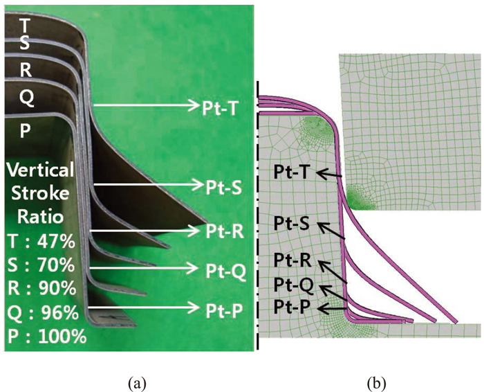
Superimposed geometries led by a vertical stroke of a die for Conventional-Forming: (a) experimental and (b) simulation results (Note: Pt-P, Pt-Q, Pt-R, Pt-S and Pt-E indicate evaluating points for simulated effective strain. The location of Pt_P is the same as Pt1 given in Fig. 2(b)). (Online version in color.)

Maximum measured microcrack depths for the formed parts produced by the vertical stroke changes of a die in Conventional-Forming. (Online version in color.)
Numerical simulations for Conventional-Forming were carried out to investigate the deformation behaviour of a workpiece during the whole forming process operation. At the beginning of forming, the contact of a die with a sheet material as illustrated in Fig. 2(a) is initially established. As the die moves vertically, the workpiece is gradually folded downwards, as described in Fig. 6. Finally, close contact of the sheet material against the punch leads to flattening of the Top and Bottom as shown in Fig. 1(a).

Locations of Pt1, Pt2 and Pt3 during forming. A die moved vertically downwards with a stroke of (a) 40 mm, (b) 60 mm and (c) 82.7 mm, respectively. (Online version in color.)
Effective strain was observed to characterize the deformation of the steel sheet during the stamping process. Figure 7 illustrates the changes of effective strain evaluated at Pt1, Pt2 and Pt3 defined in Fig. 2(b). Additionally, the position of Pt1 in the workpiece and tools were also presented to describe the strain evolution. The description in Figs. 6 and 7, indicate that effective strain mainly occurs by compressive-bending and unbending followed by a straightening during forming. For example, the effective strain continuously increases up to a stroke of 40 mm and 60 mm for Pt2 and Pt3, respectively, due to bending. Note that the location of the die and position of Pt1 and Pt2 at the stroke were captured in Figs. 6(a) and 6(b). Likewise, in the case of Pt1, the effective strain also increases up to nearly a VSR of 97% as presented in Fig. 7. Additionally, the evaluated interfacial pressure caused by a forming die in the numerical simulation is given in Fig. 8. The interfacial pressure for Pt1, Pt2 and Pt3 reaches its peak at about the stroke corresponding to that described in Fig. 6. That is, the compressed material is transformed into tension through contact with the tool. And, it is estimated that interfacial pressure appears to be the largest at Pt1 in Conventional-Forming, since the curvature gradually tends to increase as a die moves downwards. As a die continues to deform the geometry of a part, the gap between the punch and die also becomes much narrower. Therefore, a constrained workpiece underwent an unbending followed by drawing mode deformation, which straightens a wall of the product. For example, this straightening starts at a stroke of 48 mm, 66 mm and 82.7 mm for Pt3, Pt2 and Pt1, respectively, which significantly increased the effective strain. Through this forming history, the largest value in effective strain was predicted at Pt1 and the maximum microcrack depth was also measured in specimen W1. The deformation behaviors of Pt2 and Pt3 are similar with Pt1. However, a microcrack depth of 7.2 μm in specimen W2 and microcrack free in specimen W3 were observed due to the relatively smaller effective strains than occurred at Pt1 as shown in Fig. 7.

Evaluated effective strain changes at three locations for Conventional-Forming. (Online version in color.)

Evaluated interfacial pressure at three locations for Conventional-Forming. (Online version in color.)
Additionally, hot forming simulations were carried out for P, Q, R, S and T parts and the superimposed geometries led by numerical calculations for the die stroke changes are characterized in Fig. 4(b). Please note that the die objects except the case of a VSR of 47% were deliberately not displayed in Fig. 4(b). Figure 9 presents the effective strain evaluated at Pt-P, Pt-Q, Pt-R, Pt-S and Pt-T with the maximum measured microcrack depths. It is seen that the magnitude of microcracks and the effective strain increase with a larger vertical stroke. As a forming stroke increases, the curvature on the wall region of a deformed object becomes larger and the gap between tools tends to be smaller according to the description shown in Figs. 4(b) and 6. These simulation results and experimental validation indicate that the microcrack depth is dependent on the effective strain and can be reduced when the effective strain of a deformed part decreases.

In an attempt to lower effective strain, particular focus was put on the tool contact conditions and bending curvature of a workpiece during forming in direct HPF. It can be assumed that the increase in the gap between tools and the decrease of bending curvature can be acquired in Conventional-Forming when the initial position of the die is shifted to positive x-direction as defined in Fig. 2. As one approach to this, this study proposed Side-Forming in which a workpiece undergoes deformation caused by a die moving in an oblique motion. Initially, proper conditions for a forming angle as defined in Fig. 10 should be established because a small forming angle does not differ from that of Conventional-Forming and the buckling of a workpiece may happen with a much larger forming angle. Thus, thermo-mechanical coupled simulations for several forming angles were carried out to evaluate the effective strain. The forming angles of 0, 20 and 40 were initially adopted for the numerical simulations. Note that a forming angle to the vertical direction can be adjusted by changing an initial x-axis coordinate of a die with constant y- and z- axes in a finite element model as shown in Fig. 10. As a result, the calculated effective strain at Pt1 for a forming angle of 0 degrees is 0.183. However, the effective strain decreases as the forming angle increases. For example, effective strain was evaluated at Pt1 as 0.125 and 0.059 for a forming angle of 20 degrees and 40 degrees, respectively. Furthermore, various trials were conducted through changing the forming angle to reduce the evaluated effective strain at Pt1. Consequently, in this u-draw bent case, the minimum value was acquired at a forming angle of 42 degrees and the effective strain increased again for a forming angle greater than 42 degrees as presented in Fig. 11. Therefore, a forming angle of 42 degrees leading to the smallest effective strain among several conditions was finally chosen for the application of Side-Forming tool.

FE-model for Side-Forming. (Online version in color.)

Influence of a forming angle (θ) defined in Fig. 10 on the effective strain at Pt1 for Side-Forming.
The comparison of deformation behavior for Conventional-Forming and Side-Forming with a forming angle of 42 degrees is presented in Fig. 12. The status for a vertical stroke (hereafter referred to as VS) of 23 mm and 51.4 mm was captured to describe a bending curvature. For example, one end of a blank material in Conventional-Forming begins to touch the punch area corresponding to the Bottom of the product at a VS of 23 mm as presented in Fig. 12(a), while the same phenomenon given in Fig. 12(e) happens at a VS of 51.4 mm in Side-Forming. It is shown that a blank material with both ends constrained undergoes bending deformation from a VS of 23 mm in Conventional-Forming. However, a sheet material with one end free is bent until a vertical stroke reaches 51.4 mm in Side-Forming. The bending curvature of a deformed workpiece in Side-Forming is smaller than that of Conventional-Forming and no contact occurred between the die and workpiece at Pt2 and Pt3.
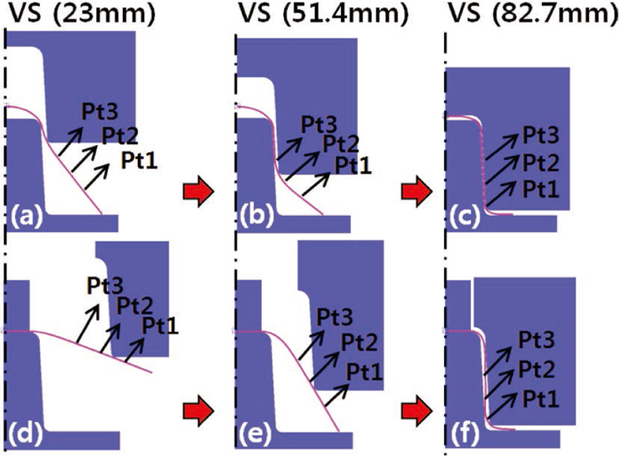
Deformed parts and the location of Pt1, Pt2 and Pt3 for Conventional-Forming and Side-Forming with a forming angle of 42 degrees (Note: VS (23 mm) indicates a Vertical Stoke of 23 mm). (Online version in color.)
The predicted temperature for Conventional-Forming and Side-Forming at three locations of draw-bent products was given in Fig. 13. During forming in HPF process, the temperature of a workpiece decreases due to heat transfer with atmospheric conditions and tools. For example, the temperature of Pt1 before contact with the tool for Conventional-Forming and Side-Forming was cooled down to 687°C and 678°C, respectively. Note that the Side-Forming shows a lower temperature because it takes slightly more time in Side-Forming with the motion angle to achieve the same vertical stroke as Conventional-Forming. And then, the temperature instantaneously drops when the cooled tool contacts the sheet material. Figure 14 shows the evaluated interfacial pressure caused by a forming die. In the case of Side-Forming, contact with a die and a deformed body occurs at the stroke of about 77 mm at Pt1 as presented in Fig. 14. Smaller interfacial pressure was observed compared with Conventional-Forming. As already shown in Fig. 12, there is no contact with a die at Pt2 and Pt3 of a hot formed part. The smaller bending curvature of Side-Forming described in Fig. 12 gives rise to the lower interfacial pressure than that of Conventional-Forming. Due to the difference in interfacial pressure given in Figs. 8 and 14, the temperature drop shown in Fig. 13 is also larger in Conventional-Forming. Thus, more deformation is also required in Conventional-Forming because of increased strength of the sheet material resulted from the temperature drop.

Comparison of predicted temperature at Pt1, Pt2 and Pt3 of draw-bent parts for Conventional-Forming and Side-Forming. (Online version in color.)

Evaluated interfacial pressure at three locations for Side-Forming. (Online version in color.)
Figure 15 illustrates the changes of effective strain evaluated at Pt1, Pt2 and Pt3 as defined in Fig. 2(b) and the position of Pt1 in the workpiece and tools. As shown in Fig. 15, the effective strain measured at Pt1 in Side-Forming was reduced to 0.025 for a VSR of 90%. Finally, the evaluated effective strain evolved in Side-Forming was much smaller than that of Conventional-Forming due to the smaller curvature and a comparatively larger gap between a punch and die compared with Conventional-Forming.
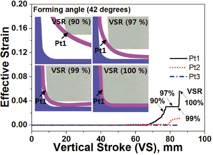
Effective strain changes at three locations for Side-Forming with a forming angle of 42 degrees. (Online version in color.)
The experiment was performed using the Side-Forming tool presented in Fig. 16. The galvanized steel sheet was heated at 900°C for 5 minutes and shifted to a press with a transfer time of 10 seconds. A ram of the hydraulic press moved vertically downwards with a velocity of 25 mm/s. The forming angle of 42 degrees for the vertical movement of the press was converted by a sliding motion in the Side-Forming tool. The stamped part is subsequently cooled in the tool for 20 seconds.
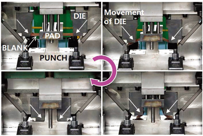
Operation of Side-Forming tool with a forming angle of 42 degrees. (Online version in color.)
After hot forming, the microscopic observations for the draw bent parts were conducted. The maximum measured microcrack depth in the deformed part was detected in specimen W1 as shown in Fig. 17. On the other hand, no microcracks were observed in specimen W2 and W3. The largest microcracks in W1, W2 and W3 specimens for Conventional-Forming and Side-Forming with a forming angle of 42 degrees were compared as shown in Fig. 18. For example, the maximum measured microcrack depth in specimen W1 for Conventional-Forming was 25.7 μm. However, the magnitude of maximum microcrack depth was significantly reduced to 6.1 μm for Side-Forming. For specimen W2, maximum microcrack depth for Conventional-Forming was 7.2 μm and no microcrack was observed in Side-Forming, respectively. As with Conventional-Forming, the size of these surface defects also tends to increase with a larger VSR in the Side-Forming. However, the maximum measured microcrack depth was seen to be less than 10 μm for the Side-Forming with a forming angle of 42 degrees. Therefore, the FE simulation and experimental validation indicated a lowered effective strain and a subsequent significant reduction in microcrack depth.

Maximum measured microcrack observed in specimen W1 for Side-Forming with a forming angle of 42 degrees. Picral etching with magnification of × 500 was used. (Online version in color.)

Comparison of the maximum measured microcrack depths for Conventional-Forming and Side-Forming with a forming angle of 42 degrees. (Online version in color.)
To verify the feasibility for a realistic application, the mechanical properties and shape accuracy (or so called springback) as the quality of the hot press formed part were measured. Normally, core hardness should be larger than 410 Hv for a quenchable boron steel after heat treatment for mechanical properties in HPF technology. In the case of Side-Forming described in Fig. 19, the hardness on the cross section of a wall of the part was successfully acquired, which means that the tool structure of Side-Forming can provide sufficient cooling performance for the heat treatment of the formed parts. The magnitude of shape accuracy from the formed configuration was also evaluated. For a finer observation of part geometry, 3-dimensional coordinate measurements were conducted. Normally, the geometrical tolerance for sheet stamping parts in a vehicle should satisfy the range of +/− 0.5 mm in consideration of assembly with mating components. Measured shape accuracy of both draw-bent parts produced by Conventional-Forming and Side-Forming can be seen in Fig. 20. The maximum difference in the Z-axis dimension between tool and part geometry at the Bottom area is 0.16 mm for Conventional-Forming and 0.27 mm for Side-Forming, respectively. Thus, shape changes for two methods are hardly noticeable with the excellent dimensional accuracy of HPF technology. Generally, sheet metal forming at high temperature is effective in reducing springback.21) Specifically, the suppressed springback in HPF is known to be caused by the plastic strain induced during the phase transformation or transformation plasticity.17) Therefore, a hot stamped product manufactured by Side-Forming satisfied the mechanical properties and shape accuracy standard for automobile components as well as significantly reduced the formation of microcracks in direct HPF under typical conditions.

Hardness distribution on the wall cross-section of the part produced by Side-Forming. (Online version in color.)
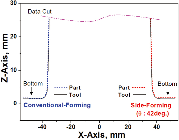
Measured shape accuracy of draw-bent parts produced by Conventional-Forming and Side-Forming. (Online version in color.)
The occurrence of microcracks in typical direct HPF with a Galvanized steel sheet was investigated with particular focus on the mechanical aspect. Microcracks occurred on the product wall-outside when the conventional-forming die moved vertically and the tool contacted the material. From the combined experimental and simulation results in Conventional-Forming, it was found that the depth of a microcrack was affected by the effective strain caused by the forming operation. In an attempt to lower the effective strain, primary consideration was given to the tool contact and bending curvature of sheet material during forming. As an approach to the consideration, the study proposed side-forming in which a workpiece undergoes deformation caused by a die moving in an oblique motion. Numerical calculations indicated that the effective strain significantly decreased and the maximum microcrack depth was observed to be less than 10 μm for the relevant direct HPF tests. Additionally, hardness and shape accuracy for the product from Side-Forming was successfully acquired, which meets the quality standard for automobile parts manufactured by HPF technology.