Abstract
Vanadium–titanium magnetite (VTM) is an important strategic resource, and now the process of Blast Furnace (BF) is the dominate route for smelting VTM. However, the difficulties of smelting VTM by BF inhibited further increase of VTM proportion in furnace burden due to its complex behavior in cohesive zone. The objective of this study is to reveal the softening–melting behavior of a high titanium sinter. The results indicated that the softening–melting properties of the experimental high titanium sinter were relatively worse than that of ordinary sinter due to its wider melting temperature interval and bad gas permeability in melting stage. The melting temperature interval of 225°C was obtained, and the permeability index (S value) of 1917 kPa·°C was calculated correspondingly. A second increase in pressure drop was observed in the softening–melting process, which may be ascribed to great difference of melting point between pig iron and slag. The mechanism on slag evolution was also clarified by interrupting the softening–melting process at characteristic temperatures. The XRD patterns indicated that initial slag phase mainly consisted of wustite, silicates and perovskite, of which the wustite content decreased gradually during the softening–melting process. The content of wustite was a crucial factor that affected the phase transformation during slag evolution.
1. Introduction
Vanadium–titanium magnetite (VTM) is an important strategic resource, which is rich in Fe, Ti, V, Cr and other valuable elements. It is the main source of vanadium and titanium metals that have been widely used in aerospace, marine engineering, medical, military, automotive, etc.1,2) VTM is abundant in Russia, South Africa, New Zealand, America and China. Particularly in China, the deposit of VTM is more than 18 billion tons in Panxi and Chengde districts. Although many non–blast furnace processes have been developed in recent years, the process of Blast Furnace (BF) is proved to be the most efficient technology for smelting VTM.3,4)
With respect to the type of VTM with high titanium content in Panxi area, the proportion of VTM in BF burden is still less than 70% due to its special smelting performances. Titanium dioxide would be over–reduced to form titanium carbonitride (Ti(C,N)), which seriously deteriorates the running conditions of BF.5) Actually, it has been demonstrated that the reduction of titanium oxides as well as the generation of Ti(C,N) mainly occurred in the cohesive zone of BF. The cohesive zone is quite a complex area that consisted of various chemical reactions, deformation of the burden, formation and separation of iron and slag. The shape and location of cohesive zone have significant impact on the distribution of gas flow and the reduction of iron–bearing burden. The pressure loss in cohesive zone accounted for about 60% of the total pressure loss in BF.6,7,8) Therefore, the study on the softening and melting behavior of Ti–bearing burden is of great significance to increase the VTM proportion in BF burden. In order to improve the softening and melting performance of Ti–bearing burden, many studies have been conducted that can be divided into three aspects: reasonable burden structure, appropriate chemical composition and suitable charging system.
In the sintering process, VTM was partly replaced by ordinary iron ores to improve the properties of Ti–bearing sinter.9,10) Increasing the proportion of pellet and decreasing the use of lump ore were also beneficial to the permeability of stock column in BF. In recent years, all the pellet burden used in BF of Panzhihua Iron & Steel (Group) CO. was made from VTM, and the smelting of BF proceeded smoothly.11) Liu et al., whose study was based on high chromic vanadium titano–magnetite, also reported that the softening and melting properties of mixed burden with a pellet ratio of 33.65% were better than other burden structures.12)
The chemical composition of BF burden was also crucial to the softening and melting properties. Several previous studies have illustrated the effect of VTM proportion or TiO2 content in mixed burden on the performance of cohesive zone.13) Increasing the basicity of Ti–bearing sinter was proved favorable to the softening and melting properties.14) In current BF operation, MgO was a desirable constituent of BF flux and an appropriate content of MgO was significant to provide a BF slag with great fluidity, viscosity and desulphurization ability.15,16,17) It has been reported that MgO should be added in pellet rather than sinter, aiming to improve the quality of pellets and adjust the MgO content of BF slag.18,19) In addition, the effect SiO2/TiO2 ratio, fluorite and Mn–bearing material has also been investigated.20,21,22)
The charging system, considered as the main mean of upper adjustment, was another important measure to BF operation. Coke–ore mixed charging is a well–known and effective route to strengthen BF operation and lower the carbon usage. Introducing coke into the ore layer was efficient to improve the permeability of cohesive zone.23,24) However, it is worthy to pay attention that the reduction of titanium oxides was also enhanced, which should be inhibited when smelting VTM. In the study of Zhao et al., it was found that the softening–melting behaviors and permeability of mixed burden were improved obviously with a coke–ore mixing ratio of 20%.25)
The chemical and phase composition of Ti–bearing burden was relatively complex, the increase in TiO2 content of burden would result in significant impact on the metallurgical properties of VTM.26) Although the softening and melting properties of VTM was quite special, it is interesting to note that the utilization coefficient of smelting VTM was not lower than that of smelting ordinary ore,5) which deserves an in-depth investigation. The previous studies mainly focused on the effect of chemical composition, burden structure and charging system on the softening–melting properties. The phase transformation as well as the slag evolution urgently need illumination. In this study, the softening–melting properties of a high Titanium VTM was initially studied and the characteristic temperatures were obtained. Then, the heating process was interrupted at characteristic temperatures to investigate phase transformation during the softening and melting process. The slag evolution in the cohesive zone was also discussed by combining the microstructure, phase composition as well as the phase diagram analysis.
2. Experimental
2.1. Materials
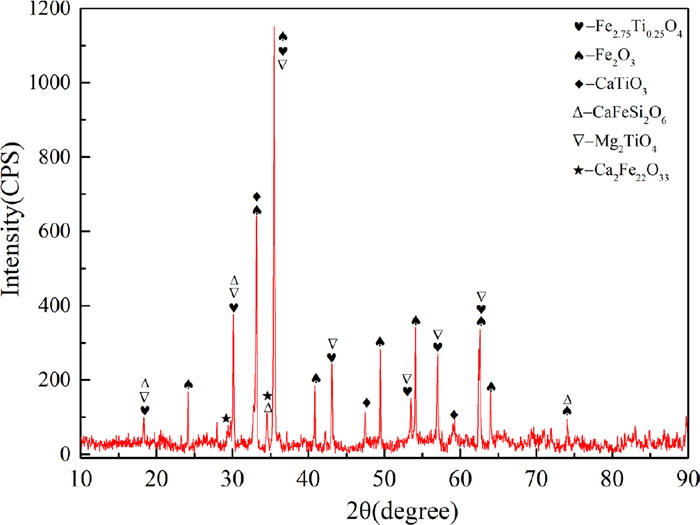
The high Titanium sinter and coke used in this study were obtained from the burden of BF in a domestic steel company. The main chemical composition of sinter is shown in Table 1. It can be seen that the TiO2 content is 6.82% and the total iron content (TFe) is 49.95%. The V2O5 content is as high as 0.35% because vanadium–titanium magnetite is the main iron ore during the sintering process. The binary basicity of the sinter is 1.82. The low iron content as well as high gangue composition of the sinter would lead to a large amount of slag during smelting, which had a great influence on the cohesive zone in blast furnace. The XRD pattern of the sinter is shown in Fig. 1. The results indicate that the main phases included hematite (Fe2O3), titanomagnetite (Fe2.75Ti0.25O4), perovskite (CaTiO3) and so on. Titanium may also exist in hematite named titanium hematite according to the previous study.20)
Table 1. Main chemical composition of the high titanium sinter (mass%).
| TFe | FeO | CaO | SiO2 | MgO | Al2O3 | TiO2 | V2O5 | Cr2O3 | R(CaO/SiO2) |
|---|
| 49.95 | 7.92 | 10.32 | 5.67 | 2.69 | 3.34 | 6.82 | 0.35 | 0.08 | 1.82 |
The softening–melting experiment was carried out according to the standard of GB/T 34211–2017 (Iron ores–Method for determination of iron reduction softening drippinger performance under load). The schematic diagram of the apparatus is shown in Fig. 2, which was mainly composed of the furnace body, gas supply system, temperature control system and data recording system. Graphite crucible with 75 mm in internal diameter and 180 mm in height was used to load the burden. Nineteen holes of 8 mm in diameter, prepared for the gas flow and dripping of the melted iron and slag, were uniformly distributed at the bottom of the crucible.

Before the experiments, both the sinter and coke were crushed to 10–12.5 mm. Coke was placed at the bottom of the crucible to form a layer of 20 mm. 500 g dried sinter was then charged above the coke layer, and the thickness of the ore layer was measured as the initial height (H0) of iron–bearing burden. Another coke layer with 40 mm in height was placed on the sinter. The graphite crucible loaded with burden was then transferred into the furnace, and load (1.0 kg/cm2) was applied on the upper coke layer through a graphite bar. The thermocouple was inserted into the hole of the graphite pressure bar to detect the temperature. The displacement sensor was reset and the gas–tightness should be kept sealed throughout the experiment. During the heating process, the temperature, displacement as well as the pressure were automatically measured and recorded by a computer. The shrinkage of the burden can be calculated as: H1/H0×100%, where H0 is the original height of iron–bearing burden and H1 is the displacement obtained from the sensor.
The heating process was started according to the experimental conditions summarized in Table 2. Several characteristic temperatures were commonly used to evaluate the softening and melting properties of iron ore, which named softening start temperature (T10), softening end temperature (T40), melting start temperature (Ts) and dripping temperature (Td). T10 and T40 represent the temperatures that the shrinkage of ore layer reaches 10% and 40%, respectively. Ts represents temperature at which the pressure drop increased substantially and Td is the temperature when pig iron or molten slag drip from the graphite crucible. Consequently, the softening temperature interval and melting temperature interval were obtained as ΔT1= T40–T10 and ΔT2= Td–Ts. Additionally, TΔPm means the temperature at which the pressure drop reaches maximum. The integral of pressure drop as function of melting temperature interval is defined as the gas permeability index (S). The softening and melting behavior were investigated by interrupting the experiments at the characteristic temperatures. When the temperature reaches T10, T40, Ts, TΔPm and Td, the experiment was finished and Ar gas was introduced immediately. The gas flow rate was kept at 10 L/min until the burden was cooled to below 200°C.
Table 2. The conditions of softening-melting experiment.
| Temperature, °C | <400 | 400–900 | 900–1000 | >1000 |
|---|
| Heating rate, °C/min | 10 | 10 | 3 | 5 |
| Heating time, min | / | 50 | 33 | / |
| Gas composition | 100% N2 | 100% N2 | 30% CO+70% N2 | 30% CO+70% N2 |
| Gas flow | 5 L/min | 5 L/min | 10 L/min | 10 L/min |
The X–ray Diffraction analysis was conducted using a diffractometer (RIGAKU D/Max 2500, Japan) under the conditions as follows: Cu Kα, tube current and voltage: 250 mA, 40 kV, scanning range: 10°–90° (2θ), step size: 0.02° (2θ) and scanning speed: 8°/min. The microstructure of roasted samples was observed by using environmental scanning electron microscope which was equipped with an energy dispersive spectrometer (ESEM, FEI QUANTA 200, Holland). ESEM images were recorded in backscatter electron mode operating in a low vacuum of 0.5 Torr and 20 keV.
3. Results and Discussion
3.1. Softening–melting Properties
The softening and melting properties of high titanium sinter were investigated and the results are shown in Fig. 3. According to the shrinkage curve in Fig. 3, volumetric expansion of the sinter is observed when the temperature is below 1000°C. The maximum expansion ratio of 2.09% in height was obtained at 985°C. The phenomenon of expansion is mainly attributed to swelling as Fe2O3 was reduced to Fe3O4 and the formation of iron whiskers.27) The reduction swelling caused by long iron whiskers may play an important role. From the results in Fig. 3 and Table 3, it can be seen that the softening start and end temperature are 1114°C and 1186°C, respectively. The temperature interval of softening stage is 72°C. The temperature of melting start and dripping is in the range of 1222–1447°C, and the temperature interval is 225°C, correspondingly.

Table 3. Characteristic temperature during the softening–melting process.
| Characteristic | T10/°C | T40/°C | ΔT1/°C | TS/°C | Td/°C | ΔT2/°C | TΔPm/°C | ΔPm/kPa | S/kPa·°C |
|---|
| Temperature | 1114 | 1186 | 72 | 1222 | 1447 | 225 | 1282 | 14.45 | 1917 |
Comparing to the softening and melting properties of ordinary sinter, the softening start temperature of high titanium sinter was generally higher.28,29) This is because the reduced FeO would combine with TiO2 to form solid solution, whose melting point was relatively higher than that of olivine (when FeO reacted with CaO and SiO2). However, the softening end temperature was usually lower than that of ordinary sinter.28,29,30) It is attributed to the fact that FeO existed in solid solution is more difficult to be reduced, which slows the reduction of FeO while facilitated the slag evolution. As a result, the temperature interval of softening for high titanium sinter was narrowed down. The temperature interval of melting and gas permeability index are more meaningful to reflect the softening and melting process. The temperature interval of melting always differs a lot due to the difference in chemical composition of the sinter (such as the contents of MgO, Al2O3, TiO2, etc.), which affects the properties of the slag.16,17) Nevertheless, it is acceptable that the maximum pressure drop was easier to be arrived and the pig iron or molten slag were difficult to drip down compared to that of ordinary sinter.31) Moreover, the gas permeability of high titanium sinter was worse, which can be reflected by the value of S. In addition, it is notable that a second increase in pressure drop was frequently observed for high titanium sinter. It may be ascribed to the flooding phenomenon and the great difference of melting point between pig iron and slag.
3.2. Morphology Transition during the Softening–melting Process
In order to illustrate the softening–melting properties and slag evolution process of high–titanium slag, the experiments were interrupted at the characteristic temperatures. The macro–morphology of the burden interrupted at different temperatures is plotted in Fig. 4.

It can be seen from Fig. 4 that the thickness of the burden decreases gradually with increase in the temperature. The burden at 1114°C was incompact and the profile of sinter was still clear. The sinter contacted with each other by point where large amount of interspace was formed among the particles. Metallic iron was generated only on the edge of the particles. The stock column softened and bonded as an integral when the temperature increased to 1186°C. Although the sinter contacted by surface, the gas permeability was still acceptable according to the pressure drop in Fig. 3. As the iron–bearing burden softened and deformed, molten materials were formed by increasing the temperature to 1222°C. The boundary of the sinter disappeared and the melts filled into the interspace resulting in obvious increase in pressure drop. The burden obtained under the conditions of maximum pressure drop (TΔPm) was entirely softened. Metallic iron aggregated together after carburization and the upper coke is pressed into the burden. The gas permeability was unfavorable as the molten materials blocked the gas passage, and it was not improved until the pig iron or molten slag began to drip through the coke layer. Flooding phenomenon of slag was easily observed in Fig. 4 due its high viscosity.
3.3. Phase Transformation
In order to find out the phase transformation during the softening and melting process. The XRD patterns of reduced samples interrupted at different temperatures are compared in Fig. 5.

The results in Fig. 5 reveal that the main phases at 1114°C included metallic iron (Fe), wustite (FexO), perovskite (CaTiO3), silicates (Ca2MgSi2O7 and MgSiO3), and titanomagnetite (Fe2.5Ti0.5O4). The original hematite had already been reduced; thus, its diffraction peaks disappeared in the XRD pattern. As the temperature increased to 1186°C, the intensity of the diffraction peak corresponding to Fe2.5Ti0.5O4 was reduced indicating that the reduction of Fe2.5Ti0.5O4 was enhanced. However, other phases were not distinctly changed by heating from 1114°C to 1186°C. Wustite is an important component that caused softening of sinter because FexO would combine with SiO2 to form low-melting point substance (such as 2FeO·SiO2). When the temperature increased to 1222°C, the diffraction peak of Fe2.5Ti0.5O4 disappeared, which showed that Fe2.5Ti0.5O4 was thoroughly reduced. Wustite still existed in the burden of 1222°C and large amount of low-melting point substance was generated, which resulted in distinct increase in the pressure drop. The samples obtained at 1282°C and 1447°C were the slag fraction as most of the metallic iron has already been aggregated. The XRD patterns indicate that the phases of slag were mainly composed of silicates and perovskite. The phase of CaAl2Si2O8 was newly formed compared to that below 1222°C. Meanwhile, metallic iron was also observed even at the temperature of 1447°C. It is ascribed to the reason that the viscosity of Ti–bearing slag is greater compared to that without titanium, especially when titanium oxides were reduced to form Ti(C,N).32) Metallic iron, surrounded by TiC/TiN/Ti(C,N) particles, was easily mingled into the Ti-bearing BF slag due to the high slag viscosity. Thus, the separation of metallic iron from slag would be inhibited. The increase in viscosity contributed to the fact that TiC/TiN/Ti(C.N) are a kind of substance with high melting point, which is impossible to melt under the condition of blast furnace smelting. Instead, it existed in slag in the form of solid particles to form a dispersion system. As a result, the melt should not only overcome its own internal friction, but also consume extra energy to drive the solid particles in the liquid to move together with the liquid. Therefore, the viscosity of Ti–containing blast furnace slag increased with an increase in TiC/TiN/Ti(C,N).32) In addition, the contact angle between high Ti–containing blast furnace slag (or hot metal) and TiC/TiN/Ti(C,N) is ~0°, that is, the wettability was very good. This is also an important reason why it tended to become thickening.29) It can also be observed that the diffraction peaks of FexO were obviously weaken with increase in the temperature above 1282°C.
3.4. Slag Evolution during the Softening–melting Process
Slag evolution during the softening-melting process was investigated by analyzing the microstructure transition and element migration. The microstructure of the burden interrupted at different stages is shown in Fig. 6. The results in Fig. 6(a) indicate that metallic iron was principally generated on the edge of the sinter particles. The reduction proceeded from outside to inside and the core of the sinter was still not reduced at T10. By increasing the temperature to 1186°C (T40), the reduction process was enhanced accompanied by generating a large amount of wustite. More metallic iron was also formed, and their particle size increased simultaneously, as shown in Fig. 6(b). The slag phase gradually formed in the temperature of 1114–1186°C with perovskite distributed in dispersion state. Ts is the temperature at which the pressure drop increased distinctly. It can be seen from Fig. 6(c) that metallic iron aggregated as myrmekitic texture and the slag fraction began to melt and aggregate together. The phase composition and microstructure at TΔPm was not significantly changed compared to that at Ts. Figure 6(e) shows the microstructure of slag fraction as the metallic iron has aggregated together. It can be observed that the slag fraction mainly consisted of silicates and perovskite. Additionally, a small number of metallic iron was mingled in the slag fraction, which was caused by the high viscosity of slag.12)

Figure 7 shows the SEM micrographs and EDS maps of the burden interrupted at Td. It can be seen that most of the metallic iron has aggregated to a large particle size. The slag fraction was relatively complex, in which silicates and perovskite are the main minerals. The distribution of Mg indicates that it existed in the forms of silicates (Ca2MgSi2O7 and MgSiO3, as shown in the XRD pattern), magnesium titanate (MgTiO3) and spinal (MgAl2O4). The element of Al primarily existed in silicate and spinal. Although the diffraction of wustite was not observed in the XRD pattern of 1447°C, a handful of FeO still existed by combing with TiO2 to form FeTiO3. However, perovskite (CaTiO3) is the main Ti-bearing phase, which is in agreement with the XRD patterns. Additionally, it was also observed that a small amount of C was diffusely distributed in the slag. It is deduced that the element of C was existed in the form TiC/Ti(C,N) according to the previous studies.12,28) The formation of TiC/Ti(C,N) is the key reason that caused the increase in viscosity of slag.32)

According to the above analysis, it can be concluded that wustite is a significant component during the slag evolution. Wustite is the substance that resulted in forming initial slag as well as the deformation of sinter. However, as the reduction proceeded, the content of FeO in slag decreased gradually from the initial slag to the ultimate slag. In order to reveal the behavior of ultimate slag, a pseudo-ternary phase diagram of SiO2–CaO–MgO was calculated by using FactSage 6.2 and the results are plotted in Fig. 8. Spot O1 represents the original components of slag, in which the contents of TiO2 and Al2O3 are 23.65% and 11.58% based on the chemical composition of sinter. Assuming that the slag was molten and uniform as the temperature increased to Td, the slag will crystallize from O1 to O2 by precipitating perovskite (CaTiO3) during the cooling process. Perovskite was observed in all the XRD patterns because it has already been formed in the sinter. Then, Mg2SiO4 and CaTiO3 would co-crystallized after reaching spot O2, and the liquid phase line transferred from O2 to O3. However, MgSiO3 rather than Mg2SiO4 is observed in the XRD patterns. Spot O3 is a ternary eutectic point, at which Mg2SiO4, CaAl2Si2O8 and CaTiO3 are co-crystallized. The diffraction peaks of CaAl2Si2O8 are observed in the XRD patterns of 1282°C and 1447°C, while more distinct diffraction peaks of Ca2MgSi2O7 are also observed. The difference between the actual slag evolution and theoretical analysis may be influenced by dynamic factors during the crystallization process.

4. Conclusions
In this study, the softening and melting properties of a high titanium sinter were investigated. The mechanism on slag evolution was also discussed by interrupting the experiments at the characteristic temperatures. The following conclusions were obtained:
(1) The melting temperature interval of 225°C was obtained for the experimental high titanium sinter, and the S value of 1917 kPa·°C was calculated correspondingly.
(2) The softening and melting properties of high titanium sinter were worse than that of ordinary sinter due to its wider melting temperature interval and bad gas permeability in the melting stage.
(3) A second increase in pressure drop was existed during the softening and melting process, which may be ascribed to the difference of melting point between pig iron and slag.
(4) The content of wustite was a crucial factor that affected the melting point of slag fraction. The slag phase mainly consisted of wustite, silicates and perovskite, of which the wustite content decreased gradually during the softening and melting process.
Acknowledgements
The authors are especially grateful to the National Key R&D Program of China (2018YFC1900500) and the Fundamental Research Funds for the Central Universities (2018CDQYCL0026) for the financial support of this research.
References
- 1) W. Lv, X. Lv, J. Xiang, K. Hu, S. Zhao, J. Dang, K. Han and B. Song: Int. J. Hydrog. Energy, 44 (2019), 4031.
- 2) J. Tang, M. Chu, C. Feng, F. Li, Y. Tang and Z. Liu: ISIJ Int., 57 (2017), 1156.
- 3) K. Hu, X. Lv, S. Li, W. Lv, B. Song and K. Han: Metall. Mater. Trans. B, 49 (2018), 1963.
- 4) J. Tang, M. Chu, C. Feng, Y. Tang and Z. Liu: ISIJ Int., 56 (2016), 210.
- 5) X. Lv, Z. Lun, J. Yin and C. Bai: ISIJ Int., 53 (2013), 1115.
- 6) Z. Gao, G. Cheng, X. Xue, H. Yang and P. Duan: Steel Res. Int., 89 (2018), 1700543.
- 7) A. Jha and S. Yoon: J. Mater. Sci., 34 (1999), 307.
- 8) T. Nishimura, K. Higuchi, M. Naito and K. Kunitomo: ISIJ Int., 51 (2011), 1316.
- 9) M. Zhou, T. Jiang, S. Yang and X. Xue: Int. J. Miner. Process., 142 (2015), 125.
- 10) A. Dehghan-Manshadi, J. Manuel, S. Hapugoda and N. Ware: ISIJ Int., 54 (2014), 2189.
- 11) W. Fu and H. Xie: Steel Res. Int., 82 (2011), 501.
- 12) J. Liu, G. Cheng, Z. Liu, M. Chu and X. Xue: Int. J. Miner. Process., 142 (2015), 113.
- 13) G. Cheng, X. Xue, T. Jiang and P. Duan: Metall. Mater. Trans. B, 47 (2016), 1713.
- 14) H. Wang, W. Zhao, M. Chu, R. Wang, Z. Liu and X. Xue: J. Cent. South Univ., 24 (2017), 39.
- 15) G. Li, Z. Tang, Y. Zhang, Z. Cui and T. Jiang: Ironmaking Steelmaking, 37 (2010), 393.
- 16) C. Feng, M. Chu, J. Tang, Y. Tang and Z. Liu: Steel Res. Int., 87 (2016), 1274.
- 17) H. Liang, M. Chu, C. Feng, J. Tang, Z. Liu and W. Wang: Ironmaking Steelmaking, 47 (2020), 106.
- 18) Z. Liu, M. Chu, H. Wang, W. Zhao and X. Xue: Int. J. Miner. Metall. Mater., 23 (2016), 25.
- 19) W. Zhao, M. Chu, C. Feng, H. Wang, Z. Liu, J. Tang and W. Wang: Ironmaking Steelmaking, 47 (2018), 388. https://doi.org/10.1080/03019233.2018.1527538
- 20) Q. Gan, Q. He, J. Li, H. Jiang and K. Sun: Iron Steel, 35 (2000), No. 4, 1 (in Chinese).
- 21) S. Cui and Q. Lv: Iron Steel Vanadium Titan., 35 (2014), No. 1, 74 (in Chinese).
- 22) S. Zhang, W. Ma, P. Zhang, J. Wen and S. Liu: Metall. Res. Technol., 116 (2019), 317.
- 23) L. Chen, Z. Liu, X. Fu, H. Yu, J. Tang and M. Chu: Iron Steel, 50 (2015), No. 1, 5 (in Chinese).
- 24) E. Mousa, A. Babich and D. Senk: ISIJ Int., 51 (2011), 350.
- 25) W. Zhao, M. Chu, H. Wang, Z. Liu, J. Tang and Z. Ying: ISIJ Int., 58 (2018), 1989.
- 26) J. Liu, G. Cheng, Z. Liu, M. Chu and X. Xue: Steel Res. Int., 86 (2015), 808.
- 27) W. Li, G. Fu, M. Chu and M. Zhu: Powder Technol., 343 (2019), 194.
- 28) W. Yang, G. Yang, H. Xing and X. Li: Iron Steel Vanadium Titan., 38 (2017), No. 4, 118 (in Chinese).
- 29) Y. Wang, J. Zhang, Z. Liu, Y. Zhang, D. Liu and C. Du: Iron Steel, 52 (2017), No. 3, 20 (in Chinese).
- 30) D. Lan, T. Li, C. Zhang and Q. Wang: Iron Steel, 53 (2018), No. 9, 7 (in Chinese).
- 31) T. Li, C. Sun, D. Lan, J. Song, S. Song and Q. Wang: ISIJ Int., 59 (2019), 245.
- 32) G. Zhang, Y. Zhen and K. Chou: ISIJ Int., 55 (2015), 922.