1. Introduction
Reduction of carbon dioxide emission is one of the most urgent problems of steelmaking industries. To solve this problem, ironmaking processes must contribute because about 70% of the energy input to the integrated steelworks is put into the ironmaking processes.1,2,3) Major reducing agent used in the ironmaking processes is coal, and its usage directly influences the carbon dioxide emission. Thus various research and development approaches to decrease the carbon usage in the blast furnace process, such as control of coke reactivity and close arrangement of iron oxide and carbonaceous materials,4,5,6,7) utilization of hydrogenous reducing agent,8,9,10) enhancement of hydrogen reduction,11,12) and mixed charging of iron bearing and carbonaceous materials13,14) have been carried out. Lowering the carbon input to blast furnace corresponds to the decrease in the inputs of thermal energy and reducing gas that are the driving forces of the process, thus it is expected that the instability of the process operation arises. To maintain the stable and efficient blast furnace operation under low carbon conditions, it is necessary to distribute high temperature reducing gas to the whole parts of the blast furnace, further to maintain the permeability of packed bed of burden materials in the furnace.
Inside blast furnace, various powder materials such as unburnt char, coke fine and degraded iron ore, are generated and flow with the reducing gas while some parts of these powders accumulate in the packed bed. Excessive accumulation causes the trouble of burden descent in the furnace.15,16,17) Thus various researches have been made to understand the flow and accumulation of the powders in the packed bed. From 1980’s to 90’s, several empirical equations to estimate interaction forces among powder, gas flow and packed particles were proposed through the experiments to measure pressure drop, powder hold-up, powder velocity in packed bed.18,19,20,21,22,23,24) These correlation equations were applied to the simulation of powder motion in packed bed.21,22,25,16) These analyses, however, dealt with only dynamic hold-up or treated all powders as total hold-up, in other words, no static hold up was included. Afterward, several trials to treat dynamic and static hold-ups separately were made. Measurements of powder accumulation rate and state of accumulated powder were carried out21,27,28,29) and summarized as the powder exchange rate between static and dynamic hold ups.30) Using this correlation, the simulations of powder accumulation behaviors in packed bed under the separate treatment of static and dynamic powder hold-ups were carried out.31,32,33,34) In these analyses, powders were treated as artificial continuum phase and Eulerian framework was applied to formulate the powder behavior. Onthe other hand, powder motion and accumulation behaviors are characterized by the nature of discontinuous phase. Yu and Umekage35,36) applied particle tracking method to the analysis of powder behavior, and successfully reproduce powder dispersion and pressure fluctuation in packed bed. Takahashi et al.37) found local blockage phenomena which was considered as the initiation of the blockage of packed bed and discussed it from the geometrical viewpoint. Natsui et al.38) and Kikuchi et al.39) reproduced similar local blockage phenomena through large-scale simulation using the discrete element method, and Fukuda et al.40) numerically discussed the effect of powder and packed particle properties on probability of local blockage. Above-mentioned research works revealed the flow and the accumulation characteristics of powders in dry packed bed although the liquid phase existed in the packed bed of lower blast furnace. Pham et al.41) reported about the effect of powder injection on the pressure drop and liquid velocity in three-phase packed bed of gas, solid and liquid, but the effect has yet to be formulated. Kikuchi et al.42) directly observed the powder motion in irrigated packed bed, and reported the existence of liquid phase and wettability of packed particles and powder particles have large effect on powder motion and accumulation.
This study developed a contact force model taking into account the liquid intervening between particles that were able to applied to the discrete element analysis of powder motion, and the effects of liquid on powder motion was discussed.
2. Mathematical Model
The discrete element method describes the motion of bulk powder by tracking the motions of all particles in the balk. The motion of individual particle is described by the equation of motion that include the contact force among particles and objects. In the irrigated packed bed, the liquid stays on the surface of the particles. The liquid influences on the contact behavior between particles if the liquid intervenes at the contact point. Thus, the following model was developed.
2.1. Particle Motion
The discrete element method43) was applied to the analysis of powder particle motion. The equations of motion of the particles in translational and rotation directions are described by the following two equations, respectively.
|
Translational
m
i
d
v
→
i
dt
=
∑
j
N
c
(
F
→
n,j
+
F
→
s,j
)
+
m
i
g
→
+
F
→
D
| (1) |
|
Rotational
I
i
d
ω
→
i
dt
=
∑
j
N
c
r
i
F
→
s,j
-
M
r,j
F
→
s,j
|
F
→
s,j
|
| (2) |
where,
g,
m,
r,
t,
v,
I and
ω are gravitational acceleration [m s
−2], mass of particle [kg], particle radius [m], time [s], translational velocity [m s
−1], moment of inertia [kg m
2] and rotational velocity [rad s
−1], respectively. The terms
Fn,
Fs,
FD and
Mr are inter-particle contact force in normal direction [N], contact force in tangential direction [N], drag force [N] and rotational resistance force [N m]. Subscript
i and
j specify the particle of interest and the particles that contact to this particle, respectively.
Nc is number of contacting particle to particle
i. The normal and the tangential direction are defined as the direction of a line which passes the centers of two contacting particle, and perpendicular direction to this line. The Voigt model that is shown in
Fig. 1 is applied as the contact force under direct contact condition. The Voigt model describes the contact force by using a spring and a dashpot. The contact forces in normal and tangential directions can be given by the following equations.
|
Normal
F
n
=
η
n
du
dt
+
K
n
u
| (3) |
|
Tangential
F
s
=
η
s
r
i
dϕ
dt
+
K
s
r
i
ϕ
| (4) |
where
u and
ϕ are the small displacements ([m] and [rad]) in normal and tangential direction due to contact, and
K and
η are spring constant [N m
−1] and damping constant [kg s
−1], respectively. As shown in
Fig. 1, the contact model in this study includes frictional slider. Slip between the particle surfaces occurs when the tangential contact force given by
Eq. (4) is larger than the product of friction coefficient
μf and the normal contact force. Under slip condition, the tangential contact force is given by the following equation.
This particle motion model treats all particles as spherical ones. In many case, the actual particles have deformed or irregular shapes, and the rotational motion receives resistance due to the particle shape. This effect is introduced to the equation of motion as rotational resistance force
Mr in
Eq. (2), and given by
where
α and
rc are rotational friction coefficient and radius of contact circle.
44,45)
In the analysis, it is assumed that the particles move in static gas. The drag force that particle received from the gas is given by the following equation.46)
|
F
→
D
=-
C
D
π
r
i
2
⋅
1
2
ρ
g
|
v
→
i
|
v
→
i
| (7) |
In this equation, the term
CD is drag coefficient and given as functions of particle Reynolds number.
|
C
D
={
24
Re
for
Re ≤1
24
Re
for
1<Re≤2 975
0.44
for
2 975<Re
| (8) |
It is reported that the powder motion in irrigated packed bed is strongly affected by the wettability of powder and packed particles.42) In this study, the contact force model was developed for the good wettability condition, in other word, the liquid stays in the packed bed as film form on the surface of the packed particle.
When a powder particle approaches to the surface of the packed particle covered by the liquid film, the powder particle receives force from the liquid film before the powder particle contacts to the packed particle surface. The various phenomena occur during the powder contacts with liquid. When the powder particle collides with the liquid surface, the powder particle receives impact force. The powder particle further approaches to the packed particle surface, the powder particle must exclude the liquid in the film. The liquid flow induced between powder particle and packed particle due to the exclusion generates the viscous friction force, and this force acts as the resistance force to the powder particle. If the motion of powder particle has the velocity component parallel to the packed particle surface, gradient of liquid velocity is formed in the liquid film and the viscous resistance force acts to the powder particle. Even the powder particle contacts to the packed particle surface, microscopically liquid remains between two particles, and this remained liquid decrease the friction between particles. When the powder particle detaches from the liquid film, the powder particle receives the adhesive force from the liquid. Additionally, the powder particle has rotating motion, the liquid motions induced by the particle rotation generate the force. Other than these, the various form of the relative motion among powder particle, packed particle and liquid generate the forces. Among these, the cohesive force due to the liquid bridge between particles, viscous resistance forces and lubrication were modeled and included into the discrete element analysis because they are considered to have large effect on the particle motion and their theories are established.
2.2.1. Adhesive Force by Liquid Bridge
When the liquid bridge is formed between tow particles, adhesive force is generated by surface tension and negative pressure in the bridge.47) Schematic diagram of the liquid bridge between two particles are shown in Fig. 2. The liquid bridge is a rotating body of which axis coincides with the line connecting the centers of two particles. The shape of the side face is approximated by a circular arc of radius r1 [m], and the radius of the narrowest part of the bridge is r2 [m]. These two radii are given by the distance between the particles, and the adhesion force by the liquid bridge can be given by the following equation.48)
|
F
L
=π
r
2
2
γ(
1
r
1
-
1
r
2
)
+2π
r
2
γ
| (9) |
where,
γ is the surface tension of the liquid [N m
−1]. This adhesive force acts when the distance between surfaces of two particles are less than the thickness of the liquid film that is determined by the calculating condition, and added to the equation of translational motion (
Eq. (1)).
2.2.2. Viscous Resistance Force
Figure 3 shows schematic diagram of relative motion of two particles and viscous force induced by the flow of liquid intervening between two particles. When two particles approach each other by a relative velocity vn, the intervening liquid is excluded from the space between two particles. The viscous friction generated in the excluded flow turns into the resistance force to the relative motion of two particles in normal direction. This resistance force can be given by the following equation.49)
where,
η,
R and
H are viscosity of liquid [Pa s], particle radius [m] and distance between two particles [m], respectively.
When two particles that hold liquid between them move tangentially with relative velocity vt, the velocity gradient is formed in the liquid and the viscous resistance force in tangential direction acts on both particles. This tangential viscous force can be given by the following equation.50,51)
|
F
→
vt
=-6πηR
v
→
t
(
8
15
ln
R
H
+0.9588
)
| (11) |
These viscous resistance forces are included in the equation of translational motion (Eq. (1)) when the distance between two particles becomes smaller than the thickness of the liquid film. The normal viscous resistance force is taken into account when two particles approach each other.
2.2.3. Lubrication
The friction force between surfaces of two particles that directly contact each other is given by Eq. (5). When the liquid remains in the contact area, the friction force is decreased by the lubrication effect. This study employs the mixed lubrication model52) in which the contact area consists of the direct contact part and micro pool of liquid. Schematic diagram of the contact part between two particles is shown in Fig. 4. Apparent friction force can be given by sum of the solid-solid friction force and the viscous force generated in the micro-pool.
The normal force acting between the particles are supported by the solid-solid contact part and micro-pool. The solid-solid friction force
Fd is given by the product of normal solid-solid contact force and the friction coefficient, and is given by the following equation.
|
F
d
=
μ
f
(
1-L
)
F
n
| (13) |
where
L is the ratio of the force supported by the micro-pool to total normal force [–]. The ratio
L is determined by not only area ratio of the micro-pool but also the pressure in the pool. The pressure in the pool is affected by the microscopic deformation of the contact part. Thus, the actual ratio dynamically changes with shape and size of the micro-pool, solid properties, force, and so on. In this study, the force support ratio by the liquid is set at constant value (0.9 [–]). The viscous sheer force in the micro-pool
Ff is given by the following equation.
where
h and
AL are thickness of liquid [m] and area [m
2] of the micro pool.
The area of the pool is given by the difference between the particle-particle contact area and the solid-solid contact area which is obtained from the surface roughness following the method proposed by Greenwood, et al.53,54) The tangential contact force under slipping condition with intervening liquid is given by FL in Eq. (12) instead of Eq. (5).
2.3. Experiments
To validate the contact force model with intervening liquid, trajectories of particles that collide to a solid surface covered by liquid film were measured. In this experiments, a spherical particle collides to a horizontal plate. This condition was selected to realize stable liquid film with controlled thickness and for accurate measurement of relative location between the particle and the plate. Schematic diagram of experimental apparatus is shown in Fig. 5. The apparatus consists of a shallow bath, shooting port and high-speed video camera. A certain amount of liquid was poured into the horizontally-settled shallow bath and retained quietly for enough long time to form a smooth and uniform-thick liquid film. A spherical particle was injected at certain angle and velocity from a certain height, and its trajectory was recorded by the horizontally settled high-speed video camera.

In the experiment, a plastic sphere of which diameter and density were 6.0 mm and 3330 kg m−3 was injected from a height of 50 mm to depressing angle of 45° at velocity of 2.0 m s−1. The shallow bath was made of acrylic resin and has length of 600 mm, width of 100 mm and depth of 10 mm. The liquid film was formed at thickness of 1.2 mm using silicone oil having 5 different levels of kinematic viscosity. The physical properties of the silicone oils are summarized in Table 1. The ranges of kinematic viscosity and surface tension are from 1.0 to 10000 mm2 s−1 and from 16.9 to 21.3 mN m−1, respectively, and the silicon oil wet well with the plastic particle. In the latter part, the kind of silicone oil will be designated by the value of kinematic viscosity in unit of [cs] (equivalent to [mm2 s−1]).
Table 1. Physical properties of silicone oils (25°C).
| 1 cs | 10 cs | 100 cs | 1000 cs | 10000 cs |
|---|
| Density [kg m−3] | 816 | 935 | 962 | 967 | 972 |
| Viscosity [mPa s] | 0.816 | 9.32 | 96.2 | 967 | 9720 |
| Surface tension [mN m−1] | 16.9 | 20.1 | 20.9 | 21.2 | 21.3 |
The particle trajectories that are measured and calculated under the conditions of dry (no liquid film) and 1 cs liquid film are compared in Fig. 6. The 1 cs condition shows longer horizontal traveling length between first and second collisions although little difference can be seen in the maximum height after first collision between dry and 1 cs conditions. After second collision, the 1 cs condition shows lower maximum height compared to the dry condition. The simulated trajectories well reproduce the measured ones. Figure 7 shows variations of calculated horizontal velocity component of the particle around first collision under the dry and the 1 cs conditions. The particles collide to the bottom of the bath about 0.0305 s. The horizontal velocity in the dry condition decrease from 2.08 to 1.36 m s−1 due to the collision. In the 1 cs condition, the velocity decreases by 0.13 m s−1 while one in the dry condition decreases by 0.62 m s−1. This velocity decrease is mainly brought by the friction during the collision with the bath bottom. The decrease in the horizontal velocity lessened in the 1 cs condition because the liquid film decreases the friction force by the lubrication effect. In the 1 cs condition, the particle contact with the surface of the liquid film at 0.0298 s, then the particle velocity slightly decreases till the particle contact with bath bottom. Similarly, the particle velocity continues to decrease till 0.0310 s at which the particle detached from the liquid film. These gradual velocity decrease is caused by the sheer viscous force in the liquid film. The lubrication and the sheer viscous force have opposite effect on the horizontal motion of the particle. In this condition, the former has larger effect. In the 1 cs condition, the horizontal velocity component of the particle is maintained at higher level than the dry condition, and the traveling distance between first and second collision is elongated.


The particle trajectory under the 10 cs condition is shown in Fig. 8. Under this condition, the model slightly overestimates the bouncing height and the traveling distance after collision. It is considered that these differences are brought by the overestimation of particle velocity when it detaches from the liquid film. In the actual situation, the normal viscous force acts on the particle when the particle recedes, and the effects of the intervening liquid somewhat continues due to deformation and extension of the liquid film surface. Contrarily, the model disregards the normal viscous force in the detaching process. Additionally, the effect of the intervening liquid is taken into account during the distance is less than the thickness of the liquid film. It is considered that these issues result in the discrepancy of the detaching velocity. Under the 100 cs condition, similar trend is observed in the comparison.

The evaluation of the viscous forces under detaching process will be a future subject to improve the accuracy of the estimation.
Figure 9 shows the particle trajectories under the 10000 cs condition. The particle stops on the bottom of the bath without rebound. The particle shows similar motion under the 1000 cs condition, the particle stops around 62 mm after rolls over the bath bottom. The model well describes the particle motion under the conditions with very high kinematic viscosity liquid film. Figure 10 shows the variations of distance between the particle bottom and the bath bottom (hereinafter, particle height), the adhesive force and the normal viscous force. These variations are plotted against the horizontal distance from the particle shooting port. The variation of the particle height against the horizontal distance corresponds to the particle trajectory, and drawn by a downward-sloping solid line. Under the dry condition without liquid film, the particle height shows almost linear variation till the particle collides with the bath bottom. Contrarily, the particle trajectory under the 10000 cs condition curves upward after it crosses the film surface at height of 1.2 mm and distance of 56.4 mm. This is because the normal viscous force decreases the downward velocity component of the particle. At the same time, the particle receives also the sheer viscous force and the horizontal velocity component decreases. Finally, the particle almost stagnant at 57.2 mm in horizontal distance floating on the liquid film. Afterward, the particle settles down through the highly viscous fluid due to gravity. In dis process, the horizontal velocity component is almost zero and the variation of the particle height is drawn as an almost vertical line. During such particle motion, the normal viscous force decreases with the decrease in the particle velocity. The adhesive force shows almost constant value till the particle stops, afterward it increases slightly with the settling of the particle. Under these conditions, the viscous force is much higher than the adhesive force. Thus, the viscous force is dominant. It is considered that the dissipation of particle kinetic energy due to the viscous resistance rather than the adhesive force is main reason of vanishing rebound.


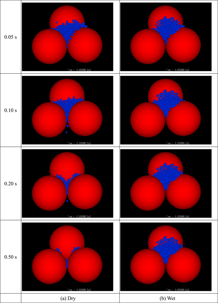
From above results, the validity and the characteristics of the developed contact force model considering the intervening liquid was confirmed. Then the model is applied to the discrete element analysis of the behavior of multiple particles under wet condition. In this analysis, 350 spherical particles of 0.5 mm in diameter are dropped on to the tree coarse spherical particles of 10.0 mm in diameter. Three coarse particles are horizontally placed in equilateral triangle arrangement and touch one another (hereinafter, these three coarse particles are called particle orifice). It is assumed that the coarse particle is covered with liquid film of which thickness and viscosity are 0.1 mm and 1.0 mPa s. The small particles are arranged in seven layers, and the bottom of the particle layer is set at the same height of the top of the coarse particles. The behaviors of the powder under the dry and the wet conditions from 0.05 to 0.5 s are shown in Fig. 11. At 0.05 s, the powders stay on the particle orifice while some powder particles enter into the space among three coarse particles. In the dry condition, number of the powder particles on the coarse particles decreases from 0.10 to 0.20 s as the powder particles pass through the orifice. At 0.50 s, only a few particles remain on the particle orifice, and these remained particles are stuck between coarse particles. Contrarily, some powder particles are trapped on the particle orifice when the powder particles contact to the particle orifice due to the viscous and adhesive forces. These trapped particles deteriorate the passing of the powder particles through the particle orifice because the effective opening of the orifice is narrowed. Consequently, many powder particles remain on the particle orifice at 0.50 s. This means that the existence of liquid wettable to the particles is likely to induce the blockage of packed bed through the powder stagnation due to the viscous and adhesive force and the narrowing of void space by the stagnant powder particles.
In this study, the particle contact force model considering the intervening liquid was developed for analyzing the motion and the accumulation of powder in irrigated packed bed. The model took into account the adhesive force, the viscous forces and the lubrication, and its validity of the model was confirmed. The discrete element analysis including newly developed contact model was applied to the motion of single powder particle colliding to a flat plate and the motion of powder particle group passing through the coarse particle orifice. It was revealed that the particle stagnation on the wet surface occurs due to not only adhesive force but also the viscous resistance force. From the results, it is suggested that the effect of the liquid phase on the powder particle motion should be properly estimated for the evaluation of flow and accumulation behavior of powder in gas-solid-liquid three-phase packed bed shown in blast furnace lower zone.


