Abstract
In this research, the three-body-type abrasive wear behavior of heat-treated multi-alloyed white cast irons, which has been used for work rolls in hot rolling stands, was investigated. Cast irons with varying C content from 1.73 to 2.34 mass% under 5 mass% of Cr, Mo, W, V each and 2 mass% Co were prepared. After annealing, the specimens were hardened from 1323 K and 1373 K austenitizing by fan air cooling. Hardened specimens (As-H) were tempered at three levels of temperatures which were at maximum tempered hardness (THTmax), lower and higher temperatures than that of THTmax (L-THTmax and H-THTmax, respectively). A rubber wheel wear tester was used to evaluate the abrasive wear resistance. It was found that the relationship between wear loss (Wl) and wear distance (Wd) was expressed by a linear function in every wear test. In each heat treatment condition, the wear rate (Rw, mg/m) value decreased as the C content rose. As-H specimens showed almost higher wear resistance than the tempered specimens. In the tempered state, the lowest Rw were mostly obtained in the THTmax specimens. The higher austenitizing temperature provided the lower Rw value. The best wear resistance was obtained in the As-H specimen with 2.34%C in the both austenitizing temperatures. The Rw was lowered roughly in proportion to an increase in hardness. However, the Rw values scattered broadly at the volume fraction of retained austenite (Vγ) values lower than 10% and then, decreased gradually as the Vγ value rose, irrespective of austenitizing temperature.
1. Introduction
Alloyed white cast irons or multi-alloyed white cast irons have been developed as materials resistant to abrasive wear for a long duration. Currently, they are widely used for steel rolling, mineral crushing or pulverizing rolls in steel-making, mining, cement industries and thermal power plant.1,2) In such products, failure by abrasive wear is directly linked to the cost performance of production. Therefore, technical innovation to increase the wear resistance of materials with an acceptable cost has been requested. Following from the great efforts of researchers, multi-alloyed white cast iron containing multiple carbide forming elements was developed in Japan.2,3) It was reported that the hot work rolls made of multi-alloyed white cast iron showed much higher performance than the conventional rolls made of Ni-hard and high Cr cast iron.3) Nowadays, the rolls in a large portion of hot rolling stands are replaced by the multi-alloyed white cast iron ones.
The basic alloy composition of multi-alloyed white cast iron is 2 mass% C (hereafter mass% is expressed by %) and 5% each of Cr, Mo, W, V.2,4,5) In addition, Co is added to improve the high temperature properties like hardness and toughness. In order that several eutectic carbides with extremely high hardness can be formed, the C content of multi-alloyed white cast iron is set to be much higher than that of high speed tool steel with similar alloying elements.2,4) During solidification, the primary austenite (γP) solidifies first from the melt and is followed by eutectic reaction of (γ + carbide). The type and morphology of crystallized carbides depends on the kind and the amount of carbide formers and the solidification rate.4) Since C in the melt is consumed to form eutectic carbides firstly, the residuals distribute into the matrix and affect the phase transformation together with other alloying elements during heat treatment. Therefore, it can be said that the C is an important element to determine both the eutectic reaction and transformation of matrix.6,7)
The heat treatment of multi-alloyed white cast irons is very important to modify their mechanical and wear properties. Generally, the heat treatment consists of annealing, hardening and tempering in the same way as high Cr cast iron or high speed tool steel. During holding at the annealing temperature, the precipitation of secondary carbides takes place. When austenitizing for hardening, some of secondary carbides are dissolved into austenite and the austenite in such state of alloy concentrations transforms to martensite during quenching. In the tempering, it is natural that martensite is tempered to (α + carbides). However, it must be noted that in multi-alloyed white cast irons, the precipitation of special carbides, the so-called carbide reaction, occurs at a high tempering temperature. The retained austenite left after hardening also precipitates the secondary carbides during tempering, and then transforms into martensite in the later cooling as well. The precipitation of special carbides with very high hardness in the tempering process performs effectively and usefully to produce a matrix with high hardness and better wear resistance.
In industrial applications, the abrasive wear process can be classified into two-body-type and three-body-type wear.1) In case of three-body-type abrasive wear, the abrasive particles move freely on the surface of machine parts. The most of such wear circumstances can be found in the ball mills and tube mills used to pulverize cement clinker, coal and blast furnace slag. However, it can be said that the wear of hot work roll is a sort of abrasive wear because it occurs by friction through oxides produced between roll and hot steel plate. Since the abrasive wear behavior in the industrial application is very complex, it is essential to clarify the effects of alloying element and heat treatment condition on the microstructure and wear resistance. In spite of wear tests having been carried out in many laboratories, the test data are often invalid for practical use.1) Therefore, further research is needed to evaluate the abrasive wear resistance to ensure that the practical applications are successful in the industrial field.
Research on solidification sequence2,4) and heat treatment behavior of multi-alloyed white cast irons with the basic alloy composition has already been reported.6,7,8,9,10) Though there have been some studies on the abrasive wear resistance of multi-alloyed white cast iron,11,12,13,14,15,16,17) there has been little systematic research on abrasive wear resistance related to alloying element and heat treatment conditions.11,15) In previous work,7) the effect of C content on heat treatment behavior of multi-alloyed white cast iron was clarified. In this study, the three-body-type abrasive wear behavior of multi-alloyed white cast irons with varying C content was investigated relating to the heat treatment behavior.
2. Experimental Procedures
2.1. Preparation of Test Specimens
Charge calculation for target chemical composition was carried out. A total of 30 kg of materials consisting of mild steel, pig iron, ferro-alloys and pure metals were melted to 1853 K in a high frequency induction furnace. After holding for 600 s, the melt was poured from 1763 to 1793 K into preheated CO2 sand molds in Y-block shape with sufficient riser as shown in Fig. 1(a). The surface of the top riser was immediately covered with dry exothermic powder to prevent rapid cooling of the risers. The riser was cut off and a rectangular block of 50 × 50× 200 mm was obtained as shown in Fig. 1(b). The substantial block was supplied to annealing to remove the internal stress and micro-segregation produced during solidification. After annealing, the block was sectioned at 7 mm in thickness by a wire-cutting machine to obtain test pieces as shown in Fig. 1(c). In order to decide the C content of specimens, a parameter of carbon balance (Cbal) which tells the C concentration of the matrix in equilibrium condition, was introduced. It is expressed by the following equations.2,7)
|
%
C
Stoich
=0.060%Cr+0.063%Mo+0.033%W+0.235%V
|
Here, %C is C content of the cast iron and %C
Stoich is stoichiometric amount of carbon that combines with all of the carbide forming elements in the cast iron. Therefore, a positive value of C
bal means that an excess of carbon remains in the matrix and a negative value means that the carbon is not saturated in the matrix. The chemical compositions and C
bal values of the test specimens are summarized in
Table 1.
Table 1. Chemical compositions and carbon balance (C
bal) of the specimens.
| Specimen | Element (mass%) | %Cbal |
|---|
| C | Si | Mn | Cr | Mo | W | V | Co |
|---|
| No. 1 | 1.73 | 0.50 | 0.49 | 5.09 | 5.05 | 4.98 | 5.05 | 2.03 | −0.25 |
| No. 2 | 2.00 | 0.53 | 0.49 | 4.96 | 4.98 | 4.98 | 5.01 | 2.03 | +0.05 |
| No. 3 | 2.34 | 0.54 | 0.49 | 4.98 | 5.02 | 4.98 | 5.04 | 1.98 | +0.38 |
Heat treatment cycles of specimen are summarized in Fig. 2. The substantial block in Fig. 1(b) was coated with an anti-oxidation paste and supplied to annealing. The annealing was carried out at 1223 K for 18 ks and followed by furnace cooling (FC). The test pieces in Fig. 1(c) were austenitized at 1323 K and 1373 K in a vacuum furnace and held for 3.6 ks. After that, the test pieces were hardened by fan air cooling (FAC) to room temperature. Hardened specimens (As-H) were tempered for 12 ks at three levels of temperatures where the maximum tempered hardness was obtained (THTmax), lower and higher hardness than that of THTmax (L-THTmax and H-THTmax, respectively). These tempering temperatures were selected from the tempered hardness curve which had already been obtained experimentally in previous work.7) The selected temperatures are summarized in Table 2. After holding at each tempering temperature, the test piece was cooled in air (AC) to room temperature.

Table 2. Selected tempering temperature of specimens.
| Specimen | Tempering temperature (K) |
|---|
| 1323 K austenitizing | 1373 K austenitizing |
|---|
| L-THTmax | THTmax | H-THTmax | L-THTmax | THTmax | H-THTmax |
|---|
| No. 1 (1.73%C) | 723 | 798 | 823 | 723 | 798 | 823 |
| No. 2 (2.00%C) | 723 | 798 | 840 | 723 | 798 | 850 |
| No. 3 (2.34%C) | 723 | 798 | 850 | 748 | 823 | 882 |
The microstructure of specimens was observed using an Optical Microscope (OM, Nikon ECLIPSE, LV150, Japan) and Scanning Electron Microscope (SEM, HITACHI Miniscope, TM3000, Japan). The test pieces with mirror polishing were etched by Murakami’s and Villella’s reagents to reveal the microstructure. The macro-hardness or total hardness was measured using a Vickers hardness tester with a load of 294.2 N (30 kgf) by which the compressed area can cover both of eutectics and primary matrices. The micro-hardness or matrix hardness was measured in primary austenite region using a Micro-Vickers hardness with a load of 0.98 N (0.1 kgf). In each specimen, the hardness was randomly measured at five locations and average values were adopted.
2.4. Measurement of Volume Fraction of Retained Austenite (Vγ)
The volume fraction of retained austenite (Vγ) was measured using an X-ray diffraction method.6,7,9,10,11,18) A mirror-polished bulk sample was set on a special sample stage with the function of a rotating and swinging goniometer to cancel the effect of the preferred crystal orientation of austenite.18) The X-ray beam was Mo-Kα characteristic line (λ = 0.0711 nm) with Zr filter. The scanning range was from 24 to 44 degrees by 2θ. As an example, the X-ray diffraction pattern of specimen No. 2 (2.00%C) hardened from 1323 K austenitizing is shown in Fig. 3. For quantitative calculation, the diffraction peaks of (200)α and (220)α planes for ferrite (α) or martensite (M) as well as (220)γ and (311)γ planes for austenite (γ) were used, respectively. The area bounded by each peak was calculated by image analysis software. The Vγ value was calculated from three combinations of peak areas, (220)α−(311)γ, (200)α−Σ(220,311)γ and Σ(200,220)α−(311)γ and the average value was adopted.

The surface roughness (Ra-max) of each specimen was controlled at less than 1 μm using a grinding machine (OKAMOTO, GRIND-X, PFG450DXA, Japan). A schematic drawing of the rubber wheel abrasive wear tester (TOKUSHUDENKYOKU RUBBER WHEEL WEAR TESTER, TAT-10, Japan) following the ASTM-G65 standard is provided in Fig. 4(a). The silica sand was used as abrasive material and the representative image is shown in Fig. 4(b). The grain-size distribution and volume fraction of main components of silica sand particles are summarized in Table 3. The sand was fed at approximately 250–300 g/min to the contacting faces between the mm diameter 250 rotating rubber wheel and the surface of the test piece. The test was conducted at a rotation speed of 120 rpm under the load of 85.32 N (8.7 kgf). The rubber wheel rotated in the same direction as the flow of the abrasives. At every 1000 revolutions or at wear distance 785.5 m, the weight of the test piece was measured using a high precision digital balance with 0.1 mg accuracy and the weight loss was obtained. The test was continued repeatedly for four times or at wear distance of 3142 m for one test piece on the same worn area. The sum of the four tests was taken as the total wear loss.

Table 3. Size distribution and volume fraction of main components of sand particles.
| Size distribution | Volume fraction of components |
|---|
| Mesh | % | Component | vol% |
|---|
| 35 | 2.0 | SiO2 | 95.6 |
| 48 | 51.7 | Al2O3 | 2.27 |
| 60 | 38.1 | Fe2O3 | 0.05 |
| 80 | 7.7 | | |
| 100 | 0.3 | | |
| −100 | 0.2 | | |
3. Experimental Results
3.1. Characterization of Test Specimens
To illustrate the total microstructure of specimens with different C contents, the As-H specimens hardened from 1373 K austenitizing were representatively selected and their microphotographs are shown in Fig. 5. It is the fact that the volume fractions of eutectic and primary areas in the multi-alloyed white cast iron did not totally change much from the as-cast state by heat treatment because the crystallized carbides have high thermal stability.5,19) All the specimens showed hypoeutectic structure consisting of primary austenite dendrite (γp) and eutectic structures (γ+carbide). The type and morphology of crystallized carbides in multi-alloyed white cast iron with basic alloy composition of 2%C-5%Cr-5%Mo-5%W-5%V were clarified by Wu et al.4) and Hashimoto et al.5) They reported that the eutectic carbides were mainly MC and M2C types with some amount of M7C3 type. Besides, each carbide type showed different morphology. The MC carbide had nodular morphology while the M2C carbide showed fine lamellar morphology. By contrast, the eutectic M7C3 carbide was rod-like or ledeburitic morphology. It is known that the crystalized carbides in multi-alloyed white cast iron can be distinguished by Murakami’s reagents, that is, the M2C and M7C3 carbides were attacked but the MC carbide was not.1,2,4,5,6,7,8,9,10,11) Therefore, the eutectic carbides of all the specimens were almost MC and M2C types.

The area fraction of γp and eutectic structures of specimens in Fig. 5 was quantitatively measured by image analysis software and the results are shown in Fig. 6. It was found that the area fraction of γp decreased as the C content rose and instead, that of total eutectic structures which was sum of (γ+MC) and (γ+M2C) eutectics increased. The (γ+MC) and (γ+M2C) eutectics increased progressively according to the C content. This indicates that an increase in C content is promoted by the crystallization of MC and M2C eutectic carbides.

The SEM microphotographs of As-H specimens are displayed in Fig. 7. The matrices of all the specimens are composed of fine secondary carbides (Cs), martensite (M) and retained austenite (γR). The type of precipitated secondary carbides in heat-treated multi-alloyed white cast iron with basic alloy composition was clarified by Hashimoto et al.19) using XRD and TEM analyses. They reported that the precipitated carbides in hardened-tempered state were MC, M6C and M7C3 types. Though it is difficult to identify the type of secondary carbides in this study, they could be MC, M6C and M7C3 types as reported in the literature.19) Comparing the matrix structure in both the austenitizing temperatures, the number of precipitated carbides is less in the specimens hardened from 1373 K, and instead, the retained austenite is increased.

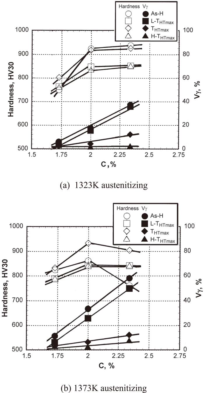
The relations among C content, macro-hardness and Vγ value of all the specimens are shown in Fig. 8(a) for 1323 K and (b) for 1373 K austenitizing. It was found that the hardness and Vγ value varied depending on the C content and heat treatment condition. The hardness in the as-hardened state increased as the C content increased to 2%C in both of the austenitizing temperatures. Over 2%C, however, the hardness changed little in the case of 1323 K austenitizing but it rather decreased in 1373 K austenitizing. The reason is due to an excess of soft retained austenite and a decrease in martensite reduced the matrix hardness. In the tempered state, the hardness showed similar behavior to that of the as-hardened state. The hardness of the THTmax specimen is generally higher than those of the L-THTmax and H-THTmax specimens. The Vγ value in the tempered state is naturally lower than that in the as-hardened state. The Vγ value of the L-THTmax specimen is reasonably higher than those of THTmax and H-THTmax specimens. Further details related to heat treatment behavior were reported in previous work.7)
In all of specimens, a linear relation was obtained between wear loss (Wl) and wear distance (Wd). The wear test results of all specimens are representatively shown in Fig. 9. It is evident from the diagrams that the wear loss increased in proportion to the wear distance, regardless of C content and heat treatment conditions. However, the wear loss clearly varied according to the difference of C content in specimens and the conditions of heat treatment. The largest total wear loss was obtained in the L-THTmax or H-THTmax specimen, and the smallest was in the As-H specimen except for 1.73%C hardened from 1323 K austenitizing. These results tell that the heat treatment condition plays an important role on wear behavior in each C specimen. Overall, the total wear loss was low in the specimen with high C content together with a high austenitizing temperature of 1373 K. Even if the straight line occurs at a higher position, it does not always mean a lower wear resistance. This is because the Wl at primary stage or primary wear may be removed depending on the initial surface condition. Since a linear relation was obtained with all the specimens, the wear rate (Rw, mg/m), which is expressed by the slope of each straight line, is calculated to evaluate the abrasive wear resistance.

4. Discussion
4.1. Effect of C Content on Wear Rate (Rw)
The relationship between C content and Rw value is shown in Fig. 10(a) for 1323 K and (b) for 1373 K austenitizing. The Rw value decreased as the C content increased regardless of austenitizing temperature. That is to say, the wear resistance increases alongside the increase in C content. This can be explained by the fact that C decreases the Ms temperature significantly and therefore, the amount of retained austenite in as-hardened state increases. Then, an increase of the austenite in the specimen generates a large amount of secondary carbides during tempering. Of course, it is true that alloying elements dissolved more in matrix promote more precipitation of secondary carbides. Such behaviors contribute to the secondary hardening in tempering. Moreover, it is considered that more C dissolved in martensite led to a great increase in the hardness of the martensite itself. At the same time, the increasing of C content produces more eutectic carbides which improve the wear resistance.

In order to clarify the effect of heat treatment conditions on wear behavior, the Rw values were viewed on individual heat treatment conditions as shown in Fig. 11(a) for 1323 K and (b) for 1373 K austenitizing. It is found that the Rw value decreases or the wear resistance gets better as the C content increases at each austenitizing temperature. The reason is due to the improvement of hardness as mentioned previously. Since the Rw value of each specimen varied depending on the heat treatment condition, it will be reasonable to discuss the wear resistance separately according to the matrix microstructure in each specimen.

In the specimen with 1.73%C hardened from 1323 K austenitizing, the lowest Rw value or the highest wear resistance was obtained in THTmax specimen and the highest Rw value or the lowest wear resistance was obtained in L-THTmax specimen. The As-H specimen has higher Rw value than tempered specimens. It is because the Vγ values in as-hardened specimens were very less as shown in Fig. 8. This suggests that the matrix transformed mostly to martensite during quenching. It is found in Fig. 8(a) for 1.73%C specimen that the hardness of As-H specimen was lower than tempered specimens. This is because a large portion of C and carbide forming elements are consumed to form their eutectic carbides, and less C dissolved in the matrix. In the tempered state, the special carbides with high hardness could precipitate secondarily from martensite by carbide reaction and improve the matrix hardness. It is known that the carbide reaction occurs in martensite of alloy steels with Mo, V and so on at over 773 K tempering.20) The secondary carbides precipitated raises the matrix hardness significantly in the same way as tool steels as reported by several works.1,6,7,9,10,11,20) It had been reported that the precipitated secondary carbides in heat-treated multi-alloyed white cast iron were MC, M6C and M7C3 types.19) The carbide reaction can be predicted as following processes for Mo;21)
|
Martensite(Fe,Mo,C)→M
(FeMo)
3
C→
M
(FeMo)
6
C→M
o
6
C
_
(at over 773 K)
|
VC carbide also forms from MC carbide by the carbide reaction as well. As for M
7C
3 carbide, however, it is hard to form pure Cr
23C
3 carbide because Cr and Fe preferably blend in the M
7C
3 carbide.
The SEM microphotographs of tempered specimens with 1.73%C are shown in Fig. 12. The matrices of all tempered specimens are composed of tempered martensite and fine secondary carbides with very less retained austenite. The precipitated carbides in the L-THTmax specimen are a few but those in the THTmax specimen are a lot. In the H-THTmax specimen, by contrast, the number of precipitated carbides is a few and the size is relatively larger than those in other specimens. Since the precipitated special carbides have extremely high hardness, the wear resistance must be improved.

In the case of 1373 K austenitizing, the As-H specimen showed the lowest Rw value or the highest wear resistance. It can be explained that the solubilities of C and alloying elements in austenite increased by elevating the temperature and subsequently, they lowered the Ms temperature. Hence, the matrix of As-H specimen is composed of martensite, more retained austenite and less secondary carbides compared with the lower austenitizing temperature of 1323 K. Of course, the high matrix hardness was obtained by complete hardening. The work-hardening of retained austenite during wear test is the one reason to improve the wear resistance. In the tempered sate, the Rw value decreased gradually in the order of L-THTmax, THTmax and H-THTmax specimens. Since the Vγ value of tempered specimens was less than 3%, the variation of Rw by heat treatment should be affected by the degree of the precipitation of secondary carbides in the matrix as mentioned before. It is found in Fig. 12 that the amount of precipitated carbides increased in the order of L-THTmax, THTmax and H-THTmax specimens, respectively. This order agreed well with the variation of Rw value.
In the case of 2.00 and 2.34%C specimens, the Rw values of As-H specimens were smaller than those of tempered specimens. Though the eutectic carbide changed very little in each specimen, the constitutional phases in the matrix were quite different between as-hardened and tempered states. The former consists of as-quenched martensite, carbides already existing at austenitizing, and retained austenite. The latter is composed of tempered martensite or very fine carbides, martensite transformed from residual austenite after tempering and small amount of finally remained austenite.
In the tempered state, the order of Rw values showed similar trends in the both 2.00% and 2.34%C specimens, that is, the smallest Rw value was obtained in THTmax specimens, followed by L-THTmax and H-THTmax specimens, respectively. The reason for this can be explained by the differences in matrix microstructure as representatively shown in Fig. 13 for 2.00%C specimen. It is clear that the matrix of the THTmax specimen has very fine tempered martensite, secondary carbides already existing in the as-hardened state and some residual austenite. Therefore, the matrix with the highest tempered hardness was obtained. On the other hand, the H-THTmax specimen is composed of secondary carbides newly formed by full tempering of martensite, coarse carbides cohered together and very less residual austenite. As a result, the matrix hardness became very low in the H-THTmax specimen. The L-THTmax specimens have an intermediate microstructure consisting of secondary carbides precipitated during austenitizing, tempered martensite and large amount of retained austenite. From the results mentioned above, it can be said that higher matrix hardness offers lower Rw value or better wear resistance.

When the effect of austenitizing temperature on the Rw value of high C specimens is considered, the Rw value varied in the same order in the both austenitizing temperatures. However, the Rw value was lower in the case of hardening from higher austenitizing temperature. As described previously, the solubility of C and alloying elements in austenite increased when that austenitizing temperature was elevated and subsequently, the Ms temperature was lowered. Hence, the high Vγ value is produced in the as-hardened state. The retained austenite in the as-hardened state contributes more to the secondary hardening by the tempering mainly where the precipitation of secondary carbides and the formation of martensite take place. Nevertheless, the differences in Rw among the specimens with different heat treatment are relatively small in the 2.34%C specimen. The reason could be due to the fraction of γp which made the effect on the secondary hardening decreases and then, the variation of matrix microstructure by tempering did not reflect so much to the Rw value.
4.3. Effect of Hardness on Wear Rate (Rw)
It is well known that hardness is one of the factors increasing the wear resistance and that wear resistance is generally high in cast irons with high hardness. The relationships between macro-hardness, micro-hardness and Rw value are shown in Fig. 14(a) for 1323 K and (b) for 1373 K austenitizing. In the both cases, the Rw values decreased as the hardness increased and the decreasing rates were almost the same. Under the same hardness, the specimens with higher C content clearly show lower Rw values. This is because an increase in C content causes more secondary hardening in the tempering process. These behaviors connect directly to an increase in the hardness of specimens and the wear resistance is improved. Here, the mechanism of three-body-type wear is discussed. The hardness of silica sand abrasives is about 1200 HV and lower than that of eutectic carbides with 1500–3000 HV.1) Since matrix with hardness lower than eutectics is worn preferentially, it can be said that the matrix with harder microstructure held better wear resistance.

The relationship between Vγ and Rw values is shown in Fig. 15(a) for 1323 K and (b) for 1373 K austenitizing. It was found that a similar trend was obtained with both austenitizing temperatures. The Rw value can be separated into two groups according to the Vγ value; the first group of specimens with Vγ values less than 10% and the second one of specimens with those over 10%Vγ. In the former group, the Rw values scatter widely irrespective of Vγ values. These results suggest that the Rw is not so influenced by the Vγ value. In the latter group, the Vγ value affects the Rw value, i.e., it decreases slowly as the Vγ value increases. From such results, it is considered that in this type of wear test, the work-hardening of retained austenite was not so great as to improve the wear resistance effectively because of low wear stress between abrasive particles and surface of specimen. However, there are some reports that a large amount of retained austenite decreased the matrix hardness and lowered the wear resistance.1,22) If the Vγ value is much more than that in this experimental condition, the hardness should be decreased and the Rw value will go up. To clarify the reason why the Rw values were widely distributed in the range of Vγ value lower than 10%, the Rw values were connected to micro-hardness and the result is shown in Fig. 16. It is clarified that the Rw value decreases in proportion to the micro-hardness or matrix hardness; the higher the matrix hardness, the lower the Rw value. In other words, the wear resistance is strongly influenced by the matrix hardness which is determined by the matrix microstructure in the specimen.

As mentioned in the wear test results, the wear rate (Rw) or wear resistance is significantly changed by the heat treatment condition. In order to clarify the wear mechanism, the surface of the wear-tested specimen was investigated by SEM. Examples of SEM microphotographs of 2.00%C specimens with different heat treatments are shown in Fig. 17. It was found that there were traces of grooving (G), scratching (S) and pitting (P) wears exist in the worn surface of each specimen. The direction of wearing by the abrasives is random because the abrasives could move freely on the surface of the specimen in the three-body-type wear. In addition, many pitting or spalling wears were found in all the specimens. It was also determined that wear arose mainly in the matrix areas together with scars or spalling of eutectic carbides stripped off by the abrasives. It is natural that the matrix is preferably worn more than eutectic area because the eutectics have higher hardness. It was found that the surface of As-H specimen had smaller pitting compared with those of tempered specimens. However, several traces of grooving wear appeared in the matrix due to a large amount of soft austenite. The wear in the L-THTmax and THTmax specimens occurs mainly by pitting and scratching with some grooving and those in the H-THTmax specimen are produced by larger grooving, pitting and scratching. It is clear that in the tempered state, the surface of the THTmax specimen shows less damage because of a strong matrix in which there are fine secondary carbides, tempered martensite and a small amount of retained austenite. By contrast, heavy surface damage was found in the H-THTmax specimen where the retained austenite is almost nil and coarse secondary carbides are dispersed in the matrix. These worn surface appearances agreed well with the wear test results in Fig. 9.

5. Conclusions
Three-body-type abrasive wear behaviors of multi-alloyed white cast irons with C content from 1.73% to 2.34%C under 5% of Cr, Mo, W, V each and 2% Co were investigated. After annealing, the specimens were hardened from 1323 K and 1373 K austenitizing. Then, the hardened specimens (As-H) were tempered at three levels of temperatures: a temperature giving the maximum hardness (THTmax), and lower and higher temperatures than that at the THTmax (L-THTmax, H-THTmax, respectively). The relationships among C content, hardness, volume fraction of retained austenite (Vγ) and wear behavior were clarified and connected with heat treatment conditions. The conclusions are summarized as follows:
(1) A linear relation between wear loss (Wl) and wear distance (Wd) was obtained in each specimen. The wear rate (Rw, mg/m) varied according to heat treatment conditions and C content.
(2) In all of specimens, the lowest Rw value or highest wear resistance was almost obtained in the As-H specimen and followed by the THTmax specimen. The wear resistance of the L-THTmax or H-THTmax specimen was the lowest.
(3) The Rw value decreased with an increase in the C content. This was because the increasing of C content produced more eutectic carbides and caused more secondary hardening in the tempering. The lowest Rw value or the highest wear resistance was obtained in the As-H specimen with 2.34%C regardless of austenitizing temperatures.
(4) The higher austenitizing temperature provided the smaller Rw value or larger wear resistance. The Rw value decreased progressively as the hardness increased irrespective of austenitizing temperature.
(5) The Rw values were scattered broadly in the range of Vγ value less than 10% because the hardness mainly resulted in improved wear resistance. Over 10%Vγ, the Rw value decreased gradually as the Vγ value increased. Here, the work-hardening occurred in the wearing process could compensate the drop in hardness by increasing of Vγ value. Resultantly, the wear resistance was improved.
Acknowledgement
This research project was financially supported by the Faculty of Engineering, Mahasarakham University (Fiscal year 2021). The authors appreciate the Faculty of Engineering, Mahasarakham University, the Cast Metals Laboratory of the National Institute of Technology- Kurume College and Isobe Iron Works Co., Ltd. for usage of their experimental devices. In addition, the authors appreciated the support of Dr.Adrian Roderick Plant, a native English speaker, for help with English language.
References
- 1) G. Laird, R. Gundlach and K. Röhrig: Abrasion-Resistance Cast Iron Handbook, American Foundry Society, Schaumburg, IL, (2000), 1.
- 2) Y. Matsubara, N. Sasaguri and M. Hashimoto: Proc. 4th Asian Foundry Cong., (Queensland), The Australian Foundry Institute, Queensland Division, (1996), 251.
- 3) M. Hashimoto, S. Otomo, K. Yoshida, K. Kimura, R. Kurahashi, T. Kawakami and T. Kouga: ISIJ Int., 32 (1992), 1202. https://doi.org/10.2355/isijinternational.32.1202
- 4) H.-Q. Wu, N. Sasaguri, Y. Matsubara and M. Hashimoto: AFS Trans., 104 (1996), 103.
- 5) M. Hashimoto, O. Kubo and Y. Matsubara: ISIJ Int., 44 (2004), 372. https://doi.org/10.2355/isijinternational.44.372
- 6) W. Khanitnantharak, M. Hashimoto, K. Shimizu, K. Yamamoto, N. Sasaguri and Y. Matsubara: AFS Trans., 117 (2009), 435.
- 7) J. Opapaiboon, P. Sricharoenchai, S. Inthidech and Y. Matsubara: Mater. Trans., 56 (2015), 720. https://doi.org/10.2320/matertrans.M2015001
- 8) Y. Yokomizo, N. Sasaguri, K. Nanjo and Y. Matsubara: J. JFS, 74 (2002), 9. https://doi.org/10.11279/jfes.74.9
- 9) S. Inthidech, K. Yamamoto and Y. Matsubara: Int. J. Metalcast., 15 (2021), 229. https://doi.org/10.1007/s40962-020-00449-8
- 10) S. Inthidech and Y. Matsubara: Int. J. Metalcast., 14 (2020), 132. https://doi.org/10.1007/s40962-019-00343-y
- 11) J. Opapaiboon, M. Supradist Na Ayudhaya, P. Sricharoenchai, S. Inthidech and Y. Matsubara: J. Met. Mater. Miner., 28 (2018), 94. http://jmmm.material.chula.ac.th/index.php/jmmm/article/view/444
- 12) Y. Matsubara, N. Sasaguri, K. Shimizu and S. K. Yu: Wear, 250 (2001), 502. https://doi.org/10.1016/S0043-1648(01)00599-3
- 13) K. Kusumoto, K. Shimizu, X. Yaer, Y. Zhang, Y. Ota and J. Ito: Wear, 376–377 (2017), 22. https://doi.org/10.1016/j.wear.2017.01.096
- 14) K. Kusumoto, K. Shimizu, V. G. Efremenko, H. Hara, M. Shirai, J. Ito, M. Hatate, Y. Gaqi and R. H. Purba: Wear, 426–427 (2019), 122. https://doi.org/10.1016/j.wear.2019.01.108
- 15) N. Sasaguri, K. Yamamoto, Y. Yokomizo, K. Shimizu and Y. Matsubara: J. JFS, 82 (2010), 667. https://doi.org/10.11279/jfes.82.667
- 16) O. Maranho, D. Rodrigues, M. Boccalini, Jr. and A. Sinatora: Wear, 274–275 (2012), 162. https://doi.org/10.1016/j.wear.2011.08.024
- 17) O. Maranho, D. Rodrigues, M. Boccalini and A. Sinatora: J. Therm. Spray Technol., 18 (2009), 708. https://doi.org/10.1007/s11666-009-9367-5
- 18) C. Kim: J. Heat Treat., 1 (1979), 43. https://doi.org/10.1007/BF02833237
- 19) M. Hashimoto, O. Kubo, N. Sasaguri and Y. Matsubara: J. JFS, 76 (2004), 205. https://doi.org/10.11279/jfes.76.205
- 20) G. Robert, G. Krauss and R. Kennedy: Tool Steels, ASM International, Materials Park, OH, (2000), 1.
- 21) K. Monma: Tekkouzairyougaku, Jikkyou Shuppan, Tokyo, (1980), 1.
- 22) I. R. Sare and B. K. Arnold: Metall. Mater. Trans. A, 26 (1995), 1785. https://doi.org/10.1007/BF02670766

