Abstract
To optimize the structure and injection position of top submerged lance, a three-dimensional gas-liquid two phases flow model in hot metal ladle is established based on Euler-Euler approach. The effects of the orifices arrangement, immersion depth and eccentricity of lance on the mixing time and gas total volume in ladle are investigated. A water model experiment is conducted to investigate the bubbles distribution and mixing time. The results show that, the predicted bubbly plume and mixing time agree well with the experimental photos and measured data. When the separation angle decreases from 180 deg to 45 deg, the symmetrical liquid flow field is destroyed, and a large circulation is formed in ladle. Meanwhile, the liquid velocity at the bottom of ladle becomes intense. As the separation angle reduces, the mixing time initially decreases follow by an increase, while the gas total volume becomes smaller. At a deeper immersion depth, the liquid velocity at the bottom of ladle and gas total volume are bigger. The mixing time reaches its minimum when the immersion depth is 740 mm. With the increasing of eccentricity, the liquid velocity becomes more uniformity, and the mixing time and the gas total volume in hot metal ladle gradually decrease. It is recommended to use the submerged lance with separation angle of 90 deg, immersion depth of 740 mm and eccentricity of 0.2 in present system.
1. Introduction
In steelmaking process, to produce ultralow-sulfur steel, hot metal pretreatment has become the key technology to remove sulfur element from molten iron.1,2) Currently, the hot metal pretreatment can be divided into mechanical stirring approach and gas injection approach, depending on how the molten pool is stirred.3,4) The gas injection approach is widely used in steel plants due to its advantages of deep desulfurization and good kinetic conditions. In this approach, Mg-based desulphurization agent is injected into molten iron through a submerged lance and reacts with sulfur element.5) The mechanism and behavior of desulfurization have been studied by many researchers,6,7,8,9) and their results show that the efficiency of desulfurization reaction is related to mixing behaviors of molten iron. In addition, the homogeneity of chemical compositions and temperature of molten iron is also related to mixing phenomena. For hot metal pretreatment process with fixed operation parameters, optimizing submerged lance structure is the most effective way to improve mixing behaviors. Therefore, considerable efforts have been made to optimize the structure of submerged lance in the hot metal ladle by means of physical simulation and numerical simulation.10,11,12,13,14,15)
Wu et al.10,11) designed a rotational submerged lance with two symmetrical orifices, and a physical simulation experiment was conducted to study the flow pattern in hot metal ladle. The results show that the mixing time of the liquid phase was shortened obviously by using the new lance. Moreover, to further improve the liquid flow, a pulse rotation mode was developed. Based on the characteristics of mechanical stirring method and gas injection method, Liu et al.12) developed a mechanical stirring-gas injection lance to disintegrate the injected bubbles. The mixing phenomena of liquid and the bubbles disintegration behaviors were studied in the water model of hot metal ladle. Then, the gas-liquid two phases flow behaviors in hot metal ladle with a mechanical stirring-gas injection lance was numerically calculated by Shao et al.3) And the liquid mixing behaviors were improved by changing the rotating speed and the eccentricity of the lance. Ji et al.5) further optimized the stirring model of the mechanical stirring-gas injection lance. Although rotational lance can improve liquid flow pattern and shorten the mixing time of the liquid phase, the maintenance and disposable investment costs of the rotational lance are too high. Therefore, the static lance is still used in most steel plants. Li et al.14) established the water model of hot metal ladle in a ratio of 1:8.5, and the effects of two-orifices lance, three-orifices lance and four-orifices lance on mixing time of hot metal ladle were studied. It was reported that the two-orifices lance was the best for mixing of the ladle. Tripatui et al.15) carried out physical and mathematical modelling to investigate the influences of different port configurations on the liquid flow dynamics in hot metal ladle, and an S-shaped two-orifices lance was invented, which could generate a more favourable flow profile. In addition, the study by Shao et al.3) pointed out that the gas total volume in hot metal ladle affected the chemical reaction between gas and liquid. It is necessary to study the gas total volume in hot metal ladle.
In the aforementioned researches, the improved structure of submerged lance can effectively shorten the mixing time of liquid phase. However, for static two-orifices lance, the effects of important factors such as the arrangement of orifices and the injection position of lance on the mixing phenomena and the gas total volume in hot metal ladle are not considered. Therefore, to further shorten the mixing time and increase the gas total volume in hot metal ladle, the effects of orifices arrangement, immersion depth and eccentricity of lance on the fluid flow characteristics, mixing phenomena and gas total volume in hot metal ladle are investigated. Firstly, the Euler-Euler two phases flow model through the Discrete Method is developed to obtain the steady flow field and the gas total volume. Then, on the basis of steady flow field, the mixing time of calculation model is computed by solving the tracer transport equation. Next, a 1/5th scaled plexi-glass water model of hot metal ladle is established. A camera is applied to record the distribution of bubbles, and electro conductivity meters are used to monitor the changes of local conductivity of water with time. Next, the comparisons of bubbles distribution and mixing time between the experimental and simulated data are provided, showing the applicability and accuracy of the Euler-Euler two phases flow model. Finally, the optimum orifices arrangement, immersion depth and eccentricity of lance are obtained by analyzing the mixing time and gas total volume under different conditions.
2. Model Formulation
The local gas holdup and steady liquid flow field in hot metal ladle are calculated by employing the Euler-Euler two-fluid model. Based on the steady liquid flow regime, the mixing time in the ladle is computed by solving the tracer transport equation.3)
2.1. Euler-Euler Model Equations
In Euler-Euler method, both the gas and the continuous liquid are treated as continuous media, respectively. Therefore, the continuity and momentum equations for the gas and the liquid are solved separately. The governing equations are as follows:
Continuity equation:
|
∂(
α
q
ρ
q
)
∂t
+∇⋅(
α
q
ρ
q
u
→
q
)=0
| (1) |
Momentum equation:
|
∂(
α
q
ρ
q
u
→
q
)
∂t
+∇⋅(
α
q
ρ
q
u
→
q
u
→
q
)=-
α
q
∇p+
α
q
ρ
q
g
→
+∇⋅(
α
q
μ
eff,q
(∇
u
→
q
+
(∇
u
→
q
)
T
)
)
+
F
→
q
| (2) |
where subscript q represents gas (q=g) and liquid (q=l) respectively,
αq is the gas holdup, which is the volume fraction of the gas phase in the gas-liquid mixture phase,
ρq is the density,
u
→
q
is the velocity,
p,
g
→
and
F
→
q
are the pressure, gravitational acceleration and total interphase forces respectively, the superscript
T represents the transpose of the matrix. The liquid effective viscosity
μeff,l and the gas effective viscosity
μeff,g are given by:
16,17)
|
μ
eff,l
=
μ
l
+
μ
t
+
μ
Bl
| (3) |
|
μ
eff,g
=
μ
eff,l
ρ
g
ρ
l
| (4) |
where
μl,
μt and
μBl are the molecular viscosity, turbulence viscosity and an extra term due to bubble induced turbulence respectively.
2.2. Interphase Forces Equations
The interphase forces
F
→
q
between the gas and the liquid can be expressed as:
|
F
→
l
=-
F
→
g
=
F
→
D
+
F
→
TD
+
F
→
VM
+
F
→
WL
+
F
→
L
| (5) |
Where
F
→
D
,
F
→
TD
,
F
→
VM
,
F
→
WL
and
F
→
L
are the drag force, turbulent dispersion force, virtual mass force, wall lubrication force and lift force respectively. The specific expressions of drag force, turbulent dispersion force and wall lubrication force are as follows:
18,19)
|
F
→
D
=
3
α
l
α
g
ρ
l
C
D
4d
|
u
→
g
-
u
→
l
|(
u
→
g
-
u
→
l
)
| (6) |
|
F
→
TD
=-
C
TD
C
lD
μ
tl
σ
tl
(
∇
α
l
α
l
-
∇
α
g
α
g
)
| (7) |
|
F
→
WL
=-
C
WL
ρ
l
α
g
|
(
u
→
l
-
u
→
g
)
|
2
n
→
w
| (8) |
where
CD,
CTD, and
CWL are the drag force coefficient, turbulent dispersion force coefficient, and wall lubrication force coefficient respectively, which are comprehensively described in our previous work,
20) ClD is the momentum transfer coefficient,
μtl is the turbulent kinematic viscosity of the continuous fluid,
σtl is the turbulent Schmidt number of the continuous fluid,
n
→
w
is the unit normal pointing away from the wall.
The virtual mass force is proportional to the relative acceleration of the gas phase and the liquid phase, so the virtual mass effect can occur when a bubble accelerates relative to the liquid. For the horizontal gas injection system, the virtual mass force can affect the horizontal penetration depth of bubbles and the distribution of gas holdup.20) The virtual mass force can be computed as follows:18)
|
F
→
VM
=
C
VM
ρ
l
α
g
(
d
u
→
g
dt
-
d
u
→
l
dt
)
| (9) |
where
CVM is virtual mass force coefficient.
The lift force mainly includes the Saffman force due to the shear in the mean flow and the Magnus force resulting from the asymmetric pressure distribution because of a particle rotation, and it is transverse to the direction of motion. In bubbly flow process, the lift force put the bubbles away from the bubbly plume central, thus changing the width of the plume.21) The lift force is calculated from the following expression:22)
|
F
→
L
=
C
L
ρ
l
α
g
(
u
→
g
-
u
→
l
)×(∇×
u
→
l
)
| (10) |
where
CL is lift force coefficient.
According to the study of Sano and Mori,23) the bubble diameter d is calculated as follows:
|
d=
[
(
6σ
d
0
ρ
1
)
2
+0.0248
(
Q
2
d
0
)
0.867
]
1/6
| (11) |
where
σ is gas-liquid surface tension coefficient,
d0 is the orifice diameter,
Q is the gas flow rate.
2.3. Turbulence Model
The common standard k−ε model is applied to solve the turbulent kinetic energy k and turbulent kinetic energy dissipation rate ε in gas-liquid two phases flow process, which can be expressed as follows:5,16,24)
|
∂
∂t
(
α
l
ρ
l
k)+∇⋅(
α
l
ρ
l
u
→
l
k)=∇⋅[
α
l
μ
t
σ
k
(∇k)
]+
α
l
G
k
-
α
l
ρ
l
ε+
α
l
ρ
l
k
| (12) |
|
∂
∂t
(
α
l
ρ
l
ε)+∇⋅(
α
l
ρ
l
u
→
l
ε)=∇⋅[
α
l
μ
t
σ
ε
(∇ε)
]
+
α
l
ε
k
(
C
1ε
G
k
-
C
2ε
ρ
l
ε)+
α
l
ρ
l
ε
| (13) |
where
Gk represents production rate of turbulent kinetic energy, which is calculated by Elgobashi
et al.’s work.
25) The standard values are used for the turbulence parameters:
σk =1.0,
σε=1.3,
C1ε=1.44,
C2ε=1.92.
2.4. Tracer Transport Equation
Mixing time is an important criterion for evaluating flow characteristics in metallurgical reactors. The mixing time is defined as the time when all the local tracer concentrations achieve within 5 pct deviation of the final concentration.26) In this work, the tracer transport equation is solved to compute the mixing time in hot metal ladle.
|
∂(
ρ
l
C)
∂t
+∇⋅(
ρ
l
u
→
l
C)=∇⋅[
μ
eff,l
Sc
(∇C)
]
| (14) |
where
C is the tracer concentration,
Sc is the turbulent Schmidt number.
3. Numerical Details
In this work, to describe the gas-liquid two phases flow behaviors in hot metal ladle, a 1/5th scaled calculation model of 180 ton hot metal ladle is established. The air is chosen to simulate stirring gas in the real hot metal ladle, and water is used to model the molten iron. The coalescence and breakup of bubbles are ignored, and the bubbles have the same diameter throughout the calculation domain. In addition, the chemical-reaction between the dispersed bubbles and liquid is neglected, and the gas-liquid two phases are defined as incompressible. In order to compare the simulated results with the ones of water model experiments, the geometric dimensions of the calculation model and materials parameters, which are shown in Table 1, are the same as experiment model. The boundary conditions and mesh of the calculation model are provided in Fig. 1. The structured mesh is used for the whole model, and the geometry is divided into 133800 cells. The velocity-inlet condition is applied for the two orifices based on gas flow rate, and the gas holdup is defined as 1. The initial bubble diameter is computed by the Eq. (11). The degassing condition is used on the top surface, where is outlet for the gas and a free slip wall for the liquid. No-slip condition is specified at walls.
Table 1. Geometric dimensions and materials parameters.
| Parameters | Values |
|---|
| Diameter of calculation model (up), mm | 640 |
| Diameter of calculation model (down), mm | 534 |
| Liquid depth, mm | 800 |
| Immersion depth of submerged lance, mm | 700, 720, 740, 760 |
| Gas flow rate, NL/min | 73 |
| Water density,21,27) kg/m3 | 997 |
| Air density,16) kg/m3 | 1.185 |
| Molecular viscosity of water,21,27) Pa·s | 0.001 |
| Surface tension between water and air,3,27) N/m | 0.073 |

The commercial computational fluid dynamic software CFX 15.0 combined with Fortran program is used to solve governing equations of the Euler-Euler model and turbulence model. The standard SIMPLE algorithm is used to calculate the discretized governing equations.28) Firstly, the steady state solution method is used to solve the flow field and the gas holdup distribution in hot metal ladle, and the calculation is assumed convergence when the residuals of all variables are less than 0.0001. As the flow reaches a steady state, a user defined scalar is added to simulate the solute transport. The mixing process is solved by using the transient solution method, and the time step is set as 0.1 s.
4. Experimental Details
To observe the distribution of the bubbles and validate the mathematical model, the corresponding water model experiment is conducted. The schematic diagram of the experimental set-up and profile of submerged lance are shown in Fig. 2. The water model is a vessel contained a submerged lance. The detailed descriptions of orifices arrangement and the injection position of lance in water model are illustrated in the following section. A camera is used to record the distribution of the bubbles. To measure the mixing time, a total of 24 mL saturated solution of NaCl is added into the vessel from an addition point in 0.5 s as tracer when the flow reaches a steady state, and then the mixing process is measured by electro conductivity meters to monitor the changes of local conductivity of water with time. In this study, the submerged lance has two orifices, and the mixing phenomena in the water model are improved by optimizing the separation angle between the two orifices and the injection position of the submerged lance.

5. Results and Discussions
5.1. Effect of Separation Angle between Two Orifices
The different separation angle arrangements between two orifices are illustrated in Fig. 3. In these schemes, the diameters of orifice remain the same, and the angle between two orifices decreases from 180 deg to 45 deg.
5.1.1. Bubbly Plume and Liquid Flow Characteristics
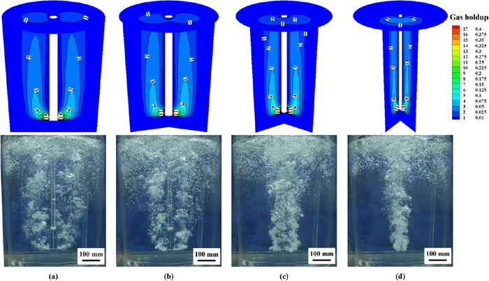
Figure 4 shows the predicted distribution of gas holdup and the bubbles distribution captured by experiment with different separation angle arrangements. Figure 5 illustrates the distribution of fluid velocity with different separation angle arrangements. The submerged lance is located at the center of hot metal ladle, and its immersion depth is 720 mm. As shown in Fig. 4, the predicted bubbles distribution agrees well with the captured experiment photo, which means that the established mathematical model can accurately simulate the gas-liquid two phases flow behaviors. It can also be seen that when the separation angle of 180 deg is adopted, two symmetrical bubbly plumes are formed with respect to the submerged lance, which induces two symmetrical liquid flow fields. With the decrease of separation angle, the two bubbly plumes gradually overlap, and the gas holdup and gas velocity increase in the bubbly plume region, which reduces the utilization of gas-stirred energy.26) It can also be found that when the separation angle decreases from 180 deg to 45 deg, the symmetrical liquid flow field is destroyed, and a large circulation is formed in ladle, as shown in Figs. 5(c) and 5(d). Additionaly, the liquid velocity at the bottom of ladle becomes intense due to the formation of the large circulation. As the separation angle decreases, the liquid velocity in bubbly plume region increases, and the location of its maximum value moves upward.
The desulfurization efficiency of molten iron is affected by mixing phenomena of hot metal ladle. In this study, to improve the mixing efficiency, the effect of separation angle on the mixing time of hot metal ladle is studied. Previous works have proved that the mixing time is affected by the tracer monitoring point and tracer addition point.3,26,29) In this study, multiple tracer addition points (A1 to A6) and tracer monitoring points (M1 to M4) are adopted, as shown in Fig. 6.

Figure 7 shows the effects of different separation angle arrangements on the mixing time in hot metal ladle. In the present work, the predicted mixing time is the average of the six mixing times predicted by adding the trace on six different addition points (A1 to A6), and the measured mixing time is average mixing time obtained from the experiment. It can be seen that the predicted mixing times are in line with the measured data. As the separation angle decreases from 180 deg to 45 deg, a large circulation is formed, which promotes the mixing of liquid phase.3) However, the overlapping bubbly plumes weaken the mixing of liquid phase. As a result, the mixing time initially decreases follow by an increase with the reduction of separation angle. Overall, the mixing time reaches its minimum when the separation angle is 90 deg.
5.1.3. Gas Total Volume
At the same experiment conditions, the increase of gas total volume in hot metal ladle indicates the extension of bubble residence time, which can promote the gas-liquid reaction. Therefore, it is necessary to investigate the gas total volume in hot metal ladle. The relationship between the gas total volume VM, gas holdup αg and cell volume Vcell is as follows:
Figure 8 depicts the gas total volume with different separation angle arrangements in hot metal ladle. It is found that when the separation angle decreases from 180 deg to 45 deg, the gas total volume decreases from 0.8317 NL to 0.7940 NL. This is because that with the reduction of separation angle, the two bubbly plumes overlap gradually, and the gas velocity in the bubbly plume becomes bigger, as shown in Fig. 5, which shortens the residence time of bubble. In addition, when the separation angle less than 90 deg, the gas total volume decreases sharply.
Overall, the effects of different separation angles on the mixing time and gas total volume are important, and the separation angle of 90 deg is recommended, although there is some reduction in the gas total volume compared to the separation angle of 180 deg.
5.2. Effect of Immersion Depth of Submerged Lance
5.2.1. Bubbly Plume and Liquid Flow Characteristics
Figures 9 and 10 show the distributions of gas holdup and liquid velocity with different immersion depths of submerged lance in hot metal ladle respectively. The separation angle between two orifices is 90 deg and the submerged lance is located in the center of ladle. As shown in these figures, for different immersion depths of the submerged lance, the shape of bubbly plume and liquid flow characteristics are basically the same. Nevertheless, as the immersion depth increases, the stirring effect of gas on liquid at the bottom of ladle is enhanced, therefore the liquid velocity at the bottom of ladle increases gradually. In addition, with the decreasing of immersion depth, the liquid velocity in the whole model becomes inhomogeneity, and the liquid velocity becomes more intense in the two phases region.
5.2.2. Mixing Time
The effects of different immersion depths of submerged lance on the mixing time in hot metal ladle are shown in Fig. 11. It is clear that when a shallow immersion depth of 700 mm is adopted, the liquid velocity at the bottom of ladle is small, as shown in Fig. 10, therefore the mixing time is relatively long. As the immersion depth increases from 700 mm to 740 mm, the liquid velocity becomes intense at the bottom of ladle, which reduces the mixing time. Further increasing of the immersion depth results in the mixing time to increase. This is because that when the immersion depth of 760 mm is applied, the channel between the submerged lance and the bottom of ladle is narrow, and the liquid flow flux through the channel is small, which is not conducive to the tracer transport between the flow fields on both sides of the submerged lance.
5.2.3. Gas Total Volume
Figure 12 illustrates the gas total volume with different immersion depths of submerged lance in hot metal ladle. The gas total volume grows from 0.7902 NL to 0.8721NL when the immersion depth increases from 700 mm to 760 mm. The reason for this phenomenon is that at a deeper immersion depth, the distance between the orifice and top surface is longer, thus extending the residence time of bubbles. Moreover, it can be seen that the gas total volume increases linearly with the increase of immersion depth, and for every 20 mm increase in immersion depth, the gas total volume increases by 0.0273 NL on average.

Comparing the mixing efficiency and gas total volume at different immersion depths of submerged lance, it is found that the optimum mixing efficiency is obtained when the immersion depth of 740 mm is adopted, and further increasing of immersion depth will worsen the mixing efficiency. Moreover, the gas total volume increases gradually with the increase of the immersion depth. The immersion depth of 740 mm is recommended to improve the mixing efficiency and gas total volume.
5.3. Effect of Eccentricity of Submerged Lance
In this chapter, the effects of different eccentricities of lance in hot metal ladle are investigated. Figure 13 provides the relative position between the eccentric lance and the bottom surface of ladle. In this simulation, the lance moves along the line 1 (in Fig. 13) to provide eccentricities of 0, 0.1, 0.2 and 0.3.
5.3.1. Bubbly Plume and Liquid Flow Characteristics
Figures 14 and 15 depict the distributions of gas holdup and fluid velocity with different eccentricities of submerged lance in hot metal ladle respectively. The separation angle between two orifices is 90 deg and the immersion depth of submerged lance is 740 mm. In these figures, as the eccentricity increases, the bubbly plume gets closer to the side wall, and the gas velocity in bubbly plume becomes greater. It can also be found that two circulations are formed when the submerged lance is located in the center of ladle. As the submerged lance moves from the center of ladle to the eccentricity of 0.3, the smaller circulation gradually decreases until it disappear, and eventually there is only one large circulation. Furthermore, with the increasing of eccentricity, the liquid velocity becomes more uniformity. However, it can be seen that with the increase of eccentricity, the liquid velocity near the side wall becomes stronger, which will shorten the service life of refractory.

Figure 16 shows the effects of different eccentricities of submerged lance on the mixing time in hot metal ladle. It is observed that when the submerged lance is located at the center, the mixing time is maximum. As the eccentricity increases from 0 to 0.3, the mixing time decreases from 18.8 s to 17.0 s. This is because that with the increase of eccentricity, the liquid velocity becomes more uniformity, which is beneficial for shortening the mixing time.26,29)
5.3.3. Gas Total Volume
Figure 17 shows the gas total volume with different eccentricities of submerged lance in hot metal ladle. It is clear from this figure that with the increasing of eccentricity, the gas total volume becomes smaller, and for every 0.1 increase in eccentricity, the gas total volume decreases by 0.0980 NL on average. The reason for this phenomenon is that the gas velocity increases as the eccentricity increases, as shown in Fig. 15, which shortens the residence time of the bubbles.

Overall, when a larger eccentricity is adopted, the mixing efficiency of hot metal ladle is higher. However, as the eccentricity increases, the gas total volume decreases, and the liquid velocity near the side wall becomes higher. When the eccentricity moves from 0 to 0.2, the mixing time decreases by 6%, while the gas total volume reduces by 2%, and the liquid velocity near the wall of hot metal ladle in Fig. 15 increases slightly. So a larger eccentricity is recommended. However, further increasing of the eccentricity to 0.3 results in the sharply increasing liquid velocity near the wall of hot metal ladle, which will shorten the service life of refractory. Therefore, in order to achieve higher mixing efficiency of hot metal ladle and longer service life of refractory, the eccentricity of 0.2 is recommended.
6. Conclusions
In this study, the Euler-Euler two phases flow model is established and effects of orifices arrangement, immersion depth and eccentricity of submerged lance on the gas holdup distribution, fluid flow characteristics and mixing phenomena in hot metal ladle are investigated. The comparisons of bubbles distribution and mixing time between experiment and numerical calculation are made. The conclusions can be drawn as:
(1) The calculated bubbles distribution and mixing time are in good agreement with the experimental photos and data, showing the applicability and accuracy of the Euler-Euler two phases flow model.
(2) When the separation angle decreases from 180 deg to 45 deg, the symmetrical liquid flow field is destroyed, and a large circulation is formed in hot metal ladle. Meanwhile, the liquid velocity at the bottom of ladle becomes intense. As the separation angle reduces, the mixing time initially decreases follow by an increase, and the gas total volume becomes smaller due to the overlapping bubbly plumes. The separation angle of 90 deg is recommended to improve the liquid flow and mixing characteristics.
(3) As the immersion depth increases, the stirring effect of gas on liquid at the bottom of ladle is enhanced, therefore the liquid velocity at the bottom of ladle increases gradually. The mixing time reaches its minimum at the immersion depth of 740 mm. When the immersion depth increases from 700 mm to 760 mm, the gas total volume grows from 0.7902 NL to 0.8721 NL. It is recommended to use the immersion depth of 740 mm.
(4) With the increasing of eccentricity, the liquid velocity becomes more uniformity, and the mixing time and the gas total volume in hot metal ladle gradually decrease. In addition, as the eccentricity increases, the liquid velocity near the side wall becomes stronger, which will shorten the service life of refractory. The eccentricity of 0.2 is recommended to achieve higher mixing efficient and longer service life of refractory.
Acknowledgements
The present study was supported by the National Key R&D Program of China (No. 2017YFC0805100), the National Natural Science Foundation of China (No. 51774077, No. 51974079, No. 51474059) and the Fundamental Research Funds for the Central Universities of China (N172504030). The authors greatly appreciate their support.
Nomenclature
Symbols
C: tracer concentration (–),
CD: drag force coefficient (–),
CTD: turbulent dispersion force coefficient (–),
CVM: virtual mass force coefficient (–),
CWL: wall lubrication force coefficient (–),
CL: lift force coefficient (–),
ClD: momentum transfer coefficient (–),
d: bubble diameter (m),
d0: orifice diameter (m),
F
→
: total interphase forces (N·m−3),
F
→
D
: drag force (N·m−3),
F
→
TD
: turbulent dispersion force (N·m−3),
F
→
VM
: virtual mass force (N·m−3),
F
→
WL
: wall lubrication force (N·m−3),
F
→
L
: lift force (N·m−3),
g
→
: gravitational acceleration (m·s−2),
Gk: production rate of turbulent kinetic energy (m2·s−3),
k: turbulent kinetic energy (m2·s−2),
n
→
w
: unit normal (–),
p: pressure (Pa),
Q: gas flow rate (m3·s−1),
u
→
: velocity (m·s−1),
VM: gas total volume (m3),
Vcell: cell volume (m3)
Greek letters
α: gas holdup (–),
ρ: density (kg·m−3),
μeff,l: liquid effective viscosity (kg·m−1·s−1),
μeff,g: gas effective viscosity (kg·m−1·s−1),
μl: molecular viscosity (kg·m−1·s−1),
μt: turbulence viscosity (kg·m−1·s−1),
μBl: bubble induced turbulence viscosity (kg·m−1·s−1),
μtl: liquid turbulent kinematic viscosity (kg·m−1·s−1),
ε: turbulent kinetic energy dissipation rate (m2·s−3),
σ: gas-liquid surface tension coefficient (N·m−1),
σtl: liquid turbulent Schmidt number (–)
Subscripts
g: gas phase
l: liquid phase
References
- 1) S. Mukawa, Y. Ueshima, M. Sano, J. Yang and M. Kuwabara: ISIJ Int., 46 (2006), 1778.
- 2) W. J. Ma, H. B. Li, Y. Cui, B. Chen, G. L. Liu and J. L. Ji: ISIJ Int., 57 (2017), 214.
- 3) P. Shao, T. A. Zhang, Z. M. Zhang and Y. Liu: ISIJ Int., 54 (2014), 1507.
- 4) M. L. He, N. Wang, M. Chen, M. Chen and C. F. Li: Powder Technol., 361 (2020), 455.
- 5) J. H. Ji, R. Q. Liang and J. C. He: ISIJ Int., 57 (2017), 453.
- 6) V. Visuri, T. Vuolio, T. Haas and T. Fabritius: Steel Res. Int., 91 (2020), 1900454.
- 7) S. Ohguchi, D. G. Robertson, B. Deo, P. Grieveson and J. H. E. Jeffes: Ironmaking Steelmaking, 11 (1984), 202.
- 8) P. Grieveson and B. Deo: Steel Res., 59 (1988), 263.
- 9) Z. S. Zou, Y. S. Zou, L. B. Zhang and N. Wang: ISIJ Int., 41 (2001), S66.
- 10) W. Wu, Y. B. Hu, L. Liu and Y. L. Ding: J. Iron Steel Res. Int., 15 (2008), 15.
- 11) W. Wu, Y. B. Hu and L. Liu: J. Univ. Sci. Technol. Beijing, 27 (2005), 140 (in Chinese).
- 12) Y. Liu, M. Sano, T. A. Zhang, Q. Wang and J. C. He: ISIJ Int., 49 (2009), 17.
- 13) W. J. Ma, H. B. Li, J. Zhang, Y. Cui and L. Sun: Metall. Res. Technol., 116 (2019), 301.
- 14) M. H. Li, D. G. Ou-yang, J. P. Rao, S. H. Zhu, Z. F. Deng and W. Luo: 11th China Iron Steel Annual Meeting, CSM, Beijing, (2017), 970.
- 15) P. Tripathi, D. S. Kumar, R. Sah and V. R. Sekhar: Ironmaking Steelmaking, 44 (2017), 421.
- 16) Z. Q. Liu, L. M. Li, F. S. Qi, B. K. Li, M. F. Jiang and F. Tsukihashi: Metall. Mater. Trans. B, 46 (2015), 406.
- 17) H. A. Jakobsen, B. H. Sannaes, S. Grevskott and H. F. Svendsen: Ind. Eng. Chem. Res., 36 (1997), 4052.
- 18) B. H. Zhu, Q. C. Liu, M. Kong, J. Yang, D. H. Li and K. Chattopadhyay: Metall. Mater. Trans. B, 48 (2017), 2620.
- 19) A. D. Burns, T. Frank, I. Hamill and J. M. Shi: Proc. 5th Int. Conf. on Multiphase Flow, The Japanese Society for Multiphase Flow, Osaka, (2004), 220.
- 20) X. Wang, S. G. Zheng and M. Y. Zhu: Ironmaking Steelmaking, 47 (2020), 915. https://doi.org/10.1080/03019233.2019.1644037
- 21) W. T. Lou and M. Y. Zhu: Metall. Mater. Trans. B, 44 (2013), 1251.
- 22) D. A. Drew and R. T. Lahey, Jr.: Int. J. Multiph. Flow, 13 (1987), 113.
- 23) M. Sano and K. Mori: Trans. Jpn. Inst. Met., 17 (1976), 344.
- 24) Y. Sato and K. Sekoguchi: Int. J. Multiph. Flow, 2 (1975), 79.
- 25) S. E. Elghobashi and M. A. Rizk: Int. J. Multiph. Flow, 15 (1989), 119.
- 26) W. T. Lou and M. Y. Zhu: ISIJ Int., 54 (2014), 9.
- 27) L. M. Li, Z. Q. Liu, B. K. Li, H. Matsuura and F. Tsukihashi: ISIJ Int., 55 (2015), 1337.
- 28) ANSYS CFX 15.0 User’s Manual, ANSYS, Inc., Canonsburg, PA, (2013).
- 29) M. Y. Zhu, I. Sawada and M. Iguchi: ISIJ Int., 38 (1998), 411.


