Abstract
In order to optimize decarburization in the RH degassing process, it is necessary to develop sensors capable of continuous and direct measurements of an oxygen concentration. However, such measurements are only possible for a few seconds with conventional sensors. Here, the effects that hinder long-time measurements by a single Mo/MoO2–type zirconia oxygen sensor were investigated and an approach to extend sensor lifetime was developed by the direct current (DC) voltage application. Reference electrodes containing molybdenum and molybdenum oxide were constructed in a single-closure tube of zirconia solid electrolyte. The EMF between the reference electrode (negative) and the sample electrode (positive) inserted in molten iron decreased from +300 mV owing to the formation of a metallic molybdenum layer on the inner surface of the zirconia tube. This layer was attributed to reduction of molybdenum oxide gas owing to oxygen diffusion from the inside to the outside of the tube. Because the oxygen diffusion coefficient in molybdenum is much lower than the oxygen ion diffusion coefficient in the zirconia, the layer disrupted oxygen transfer and reduced the EMF. Additionally, a DC voltage of 2.0 V was applied to the reference electrode and EMF recovered over 20 minutes. The molybdenum layer disappeared and the reference electrode was re-exposed to the electrolyte. Thus, the applied DC voltage enabled long-time measurements of oxygen content with a single Mo/MoO2–type zirconia oxygen sensor.
1. Introduction
In order to improve the quality and properties of steel materials, it is important to optimize the oxygen concentration in molten steel during steelmaking processes. For example, cold-rolled sheet steels for continuous annealing processes require good ductility, draw-ability, and anti-aging. Development of ultra-low carbon steel offers an effective approach to improve the mechanical properties of cold-rolled sheet steel.1,2) Ultra-low carbon steel, for which the carbon concentration is reduced from a typical 400 ppm to less than 10 ppm, is produced in a RH vacuum degassing process after refining in a converter. However, when the carbon concentration in ultra-low carbon steel is less than 15 ppm, the decarburization reaction rate decreases and the processing time increases.3,4,5)
In the RH degassing process, the CO gas pressure is reduced in a vacuum chamber, such that decarburization from molten iron proceeds by the reaction [C]+[O]→CO(g). To reduce the RH process time, there is a need to estimate the carbon concentration in the steel with high accuracy to achieve the desired decarburization degree. As one method of estimating carbon concentration, the pressure of CO gas exhaust from the RH vacuum chamber is continuously measured to calculate the carbon concentration in molten steel during the decarburization process. However, measuring the CO concentration alone offers poor estimation accuracy. A more precise estimation is possible for the carbon concentration if both the CO gas pressure as well as the oxygen concentration are continuously measured in molten steel during decarburization, based on the decarburization reaction [C]+[O]→CO(g). Various types of mathematical models have considered the mass transfer in the decarburization stage of RH processes, and the correlation between the carbon and oxygen concentration in molten steel at certain CO gas pressures has been discussed.6,7,8,9)
To measure the oxygen concentration in the molten steel, zirconia oxygen sensors are typically used. A zirconia oxygen sensor is a device that contains zirconia as a solid electrolyte stabilized by dopants for electrochemical measurement of oxygen concentration in high temperature molten metals. The measurement is based on the electromotive force arising from the oxygen potential difference between the reference electrode and the sample electrode. A Mo/MoO2 reference electrode is recommended as suitable for the oxygen sensor10) in the RH degassing process to minimize the difference in the oxygen potentials between molten steel as the sample electrode and the reference electrode to avoid oxygen transfer in the solid electrolyte.
The capability of continuous use of oxygen sensor with zirconia as solid electrolyte in actual steelmaking process has been proposed in several review papers.11,12) However, the use of a single zirconia oxygen sensor with a Mo/MoO2 reference electrode is limited to approximately 10 seconds in the RH degassing process. It has been known that the appropriate electromotive force cannot be obtained while the above type of oxygen sensor is inserted in molten steel for a long time. In this case, the absolute value of the electromotive force gradually decreases from the desired value.13) So far, there is no oxygen sensor capable of continuous measurement of the processing time of refined ultra-low carbon steel. Consequently, estimation of the carbon concentration from the oxygen concentration has yet to be realized.
Previously, a polarization in the solid electrolyte between the sample and reference electrodes was assumed as the reason for inaccurate electromotive force, and a DC voltage supply between the electrodes was proposed to prevent the polarization phenomenon.13) However, a mechanism for the decrease of the electromotive force, and the contribution of the voltage supply have not been experimentally qualified.
In order to develop a method based on the use of a zirconia oxygen sensor for continuous measurement of the oxygen concentration in molten steel for up to 30 minutes during a RH vacuum degassing process, the present study attempted to qualify the critical reason for the decreasing phenomenon of the electromotive force of a zirconia oxygen sensor with a Mo/MoO2 reference electrode by the following way. First, the electromotive force between two electrodes in molten Fe–C alloy was measured continuously for 30 minutes with a zirconia oxygen sensor and a Mo/MoO2 mixture as a reference electrode. Second, the cross-sectional microstructure of the reference electrode after the measurement was examined to identify factors preventing continuous measurement other than sintering shrinkage. In addition, an intermittent reverse bias voltage was applied to the oxygen sensor to remove inhibitors from the reference electrode and to extend the measurement time with a single oxygen sensor.
2. Experimental
2.1. Zirconia Oxygen Sensor
The construction of a solid electrolyte oxygen cell is different for various practical conditions and the design of solid electrolyte oxygen cells differs for measuring iron, steel, copper, and slag melts.10) The zirconia oxygen sensor used in this study consisted of two electrodes, including a reference electrode based on metal/oxide mixed powder and a metal wire inserted into a single-sealed tube of zirconia solid electrolyte and a sample electrode of a single metal wire. Both of electrodes were dipped into the molten iron. According to Wagner’s theory, the current flow of charge carriers in an electrolyte corresponds to the amount of electricity carried by the gradient of the electrochemical potential of the carrier. The electromotive force (EMF, E) generated between electrolytes can be expressed with the use of the oxygen ionic transfer number tion as given by the following equation, assuming that the charge carriers are oxygen ions, electrons, and holes.14)
|
E=
1
4F
∫
t
ion
d
μ
O
2
;
| (1) |
|
t
ion
=
σ
ion
σ
ion
+
σ
e
+
σ
h
.
| (2) |
In case that tion in the solid electrolyte is represented by a function of the oxygen pressure and hole conductivity is negligible in Eq. (2), the following equation is derived by Schmalzried,15) where the reference electrode is the cathode and the sample electrode is the anode:
|
E=
RT
F
ln{
(
P
O
2
ref
)
1/4
+
P
⊖
1/4
(
P
O
2
steel
)
1/4
+
P
⊖
1/4
}.
| (3) |
In Eq. (3), P⊖ is defined as the oxygen pressure where ionic conductivity is equivalent of electron conductivity of the solid electrolyte.
P
O
2
steel
is the oxygen pressure in molten steel as the sample electrode, whereas
P
O
2
ref
is defined as the oxygen pressure of the reference electrode corresponding to the equilibrium state of the metal/oxide mixture.
Here, voltage depressions in the molten iron and molybdenum electrodes are negligible due to very low electrical resistance of molten iron16) and extremely low current conduction in the oxygen sensor. Hence, it can be assumed that the measured electromotive force is approximately expressed by Eq. (3).
Zirconia solid electrolytes are often doped with MgO, CaO, and Y2O3 to stabilize zirconia in a tetragonal or cubic form over a wide temperature range. In this study, a MgO-doped partially stabilized zirconia solid electrolyte was used, which has excellent thermal shock resistance and is widely applied in steel refining processes. For the MgO-doped zirconia (91 ZrO2−9 mol% MgO), the equilibrium oxygen partial pressure between oxygen ion conduction and electron conduction, i.e. the P⊖ value in Eq. (3), has been provided by Iwase et al. as follows:17)
|
log
P
⊖
/atm=20.40-6.45×
10
4
T/K. (
T=1 273-1 873 K
)
| (4) |
It is possible to determine the oxygen pressure in molten steel
P
O
2
steel
from Eq. (3) by measuring the electromotive force E and temperature T. Furthermore, it is possible to calculate the oxygen activity aO or the oxygen concentration in the molten steel [O] equilibrated with
P
O
2
steel
from the standard free energy change ΔG0 of oxygen gas dissolving into the molten iron,18) when the henrian activity coefficient fO is assumed as unity.
|
1/2
O
2
(
g
)
=[ O ] (
1wt% in Fe
)
;
| (5) |
|
Δ
G
0
/J⋅
mol
-1
=-117 300-2.89T/K.
| (6) |
As a reference material, a Mo/MoO2 as well as Cr/Cr2O3 mixture is generally used. To avoid oxygen transfer through the solid electrolyte, the difference between
P
O
2
ref
and
P
O
2
steel
should be small. Li et al. reported that a Mo/MoO2 mixture as the reference electrode is suitable for [O] > 300 ppm and a Cr/Cr2O3 mixture is suitable for [O] < 100 ppm as weight fraction.10) Considering the typical oxygen concentration during the RH process, a zirconia oxygen sensor with a Mo/MoO2 reference electrode was used in this study. The chemical equilibrium and Gibbs free energy change of the Mo/MoO2 reference electrode are described as follows.19)
|
Mo(
s
)
+
O
2
(
g
)
=
MoO
2
(
s
)
;
| (7) |
|
Δ
G
0
/J⋅
mol
-1
=-564 634
+160.1 T/K (
T=1 533-1 925 K
)
.
| (8) |
From the above,
P
O
2
ref
is defined as 4.13×10⁻⁸ atm at T = 1873 K and the corresponding oxygen concentration in molten iron equilibrated with the
P
O
2
ref
was estimated to be 5400 ppm as weight fraction by Eqs. (3), (4), (5), (6), (7), (8).
Oxygen sensors for continuous measurement were composed of a mixed powder of Mo:MoO2 = 4:1 (as mass ratio) as a reference electrode and a single-closure tube of 8 mol% MgO-doped partially stabilized zirconia (MSZ) as a solid electrolyte. A 0.5 g portion of Mo/MoO2 powder mixture was filled into the single-closure MSZ tube, and covered by ZrO2 or MoO2 powder as a filler. The upper part of the MSZ single-closure tube was sealed with an alumina-based ceramic adhesive to prevent penetration of the reducing gas during the experiment. The connecting wires of the reference electrode and the sample electrode were both made of molybdenum to avoid contaminating impurities and generation of a thermo-electromotive force between different metals. MoO2 was used as the filler to avoid exhausting the MoO2 by reduction in case the reducing gas penetrated the reference electrode during immersion of the oxygen sensor in molten steel for a long time. Additionally, several standard oxygen sensors were prepared based on a mixture of Mo:MoO2 powders in a 9:1 (as mass ratio) as reference material and a Al2O3 filler to monitor the actual oxygen content in molten iron.
2.2. EMF Measurements
The Fe–C alloy sample was made from 400 g of electrolytic iron (Atomiron MP, 99.95% in purity, provided by Toho Zinc Co., Ltd., Tokyo, Japan, the chemical composition of impurities in the electrolytic iron are shown in Table 1) and 1.2 g of carbon pieces. Here, the added carbon was assumed to be partially consumed during the temperature rise and the oxygen concentration was expected to be adjusted within 150–400 ppm as weight fraction by the chemical equilibrium (Eq. (9)) and the relationship between the oxygen and carbon contents in molten iron (Eq. (10)):20)
|
C(
in molten iron
)
+O(
in molten iron
)
=CO(
g
)
;
| (9) |
|
[
%C
]⋅[
%O
]≈0.0024⋅
P
CO
. at 1 873 K
| (10) |
Table 1. Chemical composition of impurities in electrolytic iron sample [in ppm].
| O | C | P | S | Si | Mn | Cu | N |
|---|
| Standard | ≦200 | ≦40 | ≦20 | ≦20 | ≦20 | ≦10 | ≦10 | – |
| Representative | 100 | 20 | 5 | 8 | <5 | 1 | 1 | 5 |
The relationship in Eq. (10) is satisfied when the carbon content in the molten iron is low and the henrian activity coefficients fc and fO are regarded as unity. When the partial pressure of CO gas is determined, the relationship between carbon and oxygen content is directly determined.
The EMF measurements were performed in the experimental apparatus, as follows: An electronic furnace with a SiC heating element and an alumina tube (OD 60 × ID 52 ×1000 mm) was used. A sealing jacket with gas inlet was attached to the upper of the furnace. A small observation window was prepared in the jacket, which was initially closed by a silicon rubber stopper for sealing. The iron material in an alumina Tammann tube (OD 40 × ID 34 × 150 mm) was installed in the soaking zone of the furnace and a carbon tube (OD 40×ID 34 × 50 mm) was placed on the Tammann tube to prevent any increase in the oxygen concentration of the molten iron.
As preliminary experiments, standard oxygen sensors were immersed for a few seconds in molten iron at 1873 K under an Ar atmosphere, to measure the electromotive force at 5-min intervals for a total of 1 hour by a GL220 data logger with an insulation resistance higher than 50 MΩ (provided by Graphtec Co. Ltd., Tokyo, Japan). Multiple experiments confirmed that the electromotive force remained almost constant at approximately +300 mV during the treatment and thus the oxygen concentration did not change with time. Therefore, it was assumed that the above EMF was present for the continuous measurements. Throughout the experiments, the oxygen content in the molten iron was considered to be stable during the EMF measurements, because equivalent electromotive forces were measured by the standard oxygen sensor at the beginning and the end. As Eqs. (3), (4), (5), (6), (7), (8) are applied, the above EMF value (+300 mV) corresponded to the oxygen concentration of 120 ppm as weight fraction in the molten iron. By taking account of Eq. (10), the corresponding carbon content was estimated as [%C]≈0.20.
In contrast, Table 2 shows carbon, oxygen and molybdenum contents in a Fe–C alloy sample before and after the EMF measurement, analyzed by combustion-infrared absorption method (C, O) and X-ray fluorescence spectrometry (Mo). As shown in Table 2, the carbon concentration in the molten iron was approximately 0.3% as weight fraction, which was more than assumed in the above. Then, the oxygen concentration in molten iron was 20 ppm, which was much lower than expected. Therefore, it was indicated that almost all of the carbon pieces were dissolved in molten iron without loss during the temperature rise, and the low amount of oxygen was obtained because the actual CO gas partial pressure was lower than 1 atm. In this case, the estimated oxygen content by the EMF measurement wasn’t comparable to the actual oxygen content. It might be because the oxygen activity around the interface between molten iron and the molybdenum sample electrode locally increased because of molybdenum dissolved into molten iron, which contributes the oxygen activity to increase.18)
Table 2. Chemical composition of impurities in Fe–C alloy sample before and after EMF measurements [in ppm].
| O*) | C*) | Mo**) |
|---|
| Before EMF Measurement | 20 | 2900 | n.d.***) |
| After EMF Measurement | 18 | 2630 | 2.69×10⁴ |
*) combustion-infrared absorption method, **) fluorescence X-ray spectrometry, ***) n.d. = not detected
After the Tammann tube with iron and the carbon tube were placed in the furnace, Ar gas (99.999% in purity) was flowed in the sealed furnace from the top until the furnace atmosphere was completely replaced with Ar gas. Thereafter, the temperature of the furnace was increased to 1873 K for 5 hours and held at that temperature for over 30 minutes. The silicon rubber stopper in the upper jacket was removed to observe inside of the furnace, and dissolution of iron was confirmed. A standard oxygen sensor was immersed in the molten steel, and after measuring the electromotive force between the electrodes, the EMF value of +300 mV was confirmed.
Then, the oxygen sensor for continuous measurements was immersed in molten iron and the EMF between the electrodes was measured for 15 to 30 minutes by the GL220 data logger as mentioned above. After the oxygen sensor for continuous measurements was pulled out at the end of the measurement, another standard oxygen sensor was immersed in the molten iron to confirm that the actual oxygen content in the molten iron was unchanged.
2.3. Intermittent Direct Current (DC) Voltage Application
As mentioned in section 2.1, the oxygen concentration in molten iron that is in equilibrium with the oxygen partial pressure in the reference electrode is approximately 5400 ppm; during the experiments, the oxygen concentration in the molten iron was as low as 20 ppm. Therefore, oxygen was assumed to move from the reference electrode to the molten iron during the electromotive force measurements. Oxygen transfer presumably changed the system and prevented Eq. (3) from being satisfied. Therefore, to recover the conditions whereby the EMF could be measured, a DC voltage was applied between the electrodes to satisfy higher electric potential at the reference electrode than the sample electrode (molten iron), to induce oxygen ions to diffuse from the molten iron to the reference electrode through the zirconia solid electrolyte. The voltage application was paused when measuring the electromotive force; and between the measurements, a DC voltage of 1.0, 1.5 or 2.0 V was applied across the reference and sample electrodes. The electromotive force measurement interval was 5 minutes and the EMF measurements were performed for 30 seconds in total.
3. Result and Discussion
3.1. Continuous EMF Measurement by a Single Oxygen Sensor with Mo/MoO2 Reference Electrode
Figure 1 shows the results of the EMF measurement over time for single oxygen sensors with two kinds of filler continuously immersed in the molten iron. Regardless of whether the fillers were MoO2 or ZrO2, the EMF value gradually decreased over time from +300 mV as the initial value and approached to zero. The influence of the reducing gas penetration was considered to be negligible in this case.

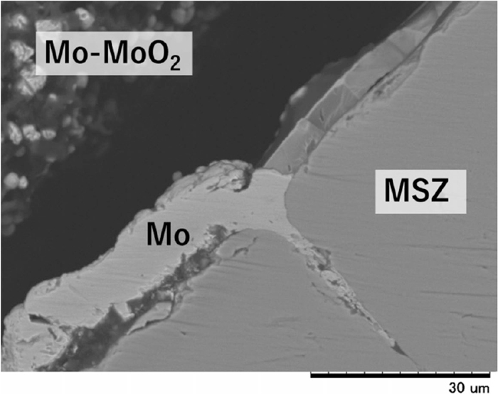
The cross-sectional microstructures of the reference electrode with the MoO2 filler after the electromotive force measurement are shown in Figs. 2 and 3. The formation of a layered structure with a thickness of approximately 10 to 30 μm was confirmed on the inner wall of the zirconia solid electrolyte. The results of elemental mapping analysis of the related samples showed this layer to be composed of metallic molybdenum. A metallic Mo layer also formed inside cracks in the zirconia solid electrolyte. This Mo layer did not likely form through sintering of the Mo powder initially provided in the reference electrode because the Mo layer covered the entire surface of the zirconia. The Mo layer was also confirmed in the cross section even at positions in the zirconia tube where no reference material was filled. This suggests that the molybdenum-bearing gas species existed the top of the vessel to be a source for a metallic Mo layer formation. In addition, the Mo layer formation was observed also in the oxygen sensor which was just kept in the reducing atmosphere in the furnace without the EMF measurement. This indicated that the Mo layer resulted from the reduction of molybdenum oxide vapor caused by oxygen transfer through the zirconia solid electrolyte from the reference electrode to the molten iron, which will be discussed below.

Initially when the oxygen sensor was immersed in the molten iron, Mo and MoO2 existed in the oxygen sensor as solids. Figure 4 shows the temperature dependence of the vapor pressure for the Mo–O system gas products at 1800 K from the information reported by Gulbransen.21) From this diagram, (MoO3)3 and MoO3 gas species had a high vapor pressure at this oxygen partial pressure whereas the equilibrium between solid Mo and solid MoO2 was satisfied. Hence, the gas phase included molybdenum oxides after the oxygen sensor was immersed in molten iron or exposed in the reducing atmosphere, and the molybdenum layer was likely formed by reduction of the molybdenum oxide gas species. Under the above PO2 conditions, each vapor pressure was estimated to be PMoO3 ≈ 7 × 10⁻⁶ atm, P(MoO3)3 ≈ 2 × 10⁻⁵ atm.

In the zirconia solid electrolyte, oxygen ions followed from the high oxygen potential side to the low oxygen potential side while there was a difference in the oxygen potential between the inside and outside of the electrolyte. At the both edges of the zirconia solid electrolyte, the following reaction among oxygen ion and electron proceeded.
Inside edge (exposed to reference electrode):
|
O
2
(
g
)
+4
e
-
→2
O
2-
| (11) |
Outside edge (exposed to sample electrode):
|
2
O
2-
→
O
2
(
g
)
+4
e
-
| (12) |
In this case, there are oxygen supply needed at the inner wall of the zirconia solid electrolyte. Therefore, when the molybdenum oxide vapor in the reference electrode partly came into contact with the inner wall of the zirconia solid electrolyte, oxygen was likely taken from the molybdenum oxide vapor contacting the inner wall of the zirconia solid electrolyte and the oxygen diffused to the molten iron at the low oxygen potential side as oxygen ions through the zirconia solid electrolyte. A metallic molybdenum layer was generated by the above-mentioned reduction of the molybdenum oxide vapor. In addition, because of electrical neutrality, the electron current reversely flowed against a flow of the oxygen ion current so that the net charge transport is zero in the zirconia solid electrolyte.22) Therefore, electrons were considered to return from outside to inside of the zirconia solid electrolyte. Consequently, metallic molybdenum layer could be even generated without the EMF measurement.
The diffusion of oxygen in the solid metallic molybdenum occurs mainly at grain boundaries, and the oxygen diffusion coefficient at grain boundaries is given as follows;23)
|
D
O
Mo
/
m
2
⋅
s
-1
=7.8×
10
-3
exp(
-
270 000
RT
)
(
T=1 423-1 723 K
)
.
| (13) |
Conversely, the diffusion of oxygen in zirconia solid electrolyte is governed by ionic conduction because the electrolyte has many oxygen ion vacancies. For, reference, the diffusion coefficient of oxygen ions in a CaO-doped stabilized zirconia solid electrolyte (a typical zirconia solid electrolyte), are reported as follows;24)
|
D
O
2-
CSZ
/
m
2
⋅
s
-1
=
0.018
-0.015
+0.098
×
10
-4
exp{
-
31 200±4 300
RT
}
(
T=1 073–1 370 K
)
.
| (14) |
From these reference diffusion coefficients
D
O
Mo
is estimated to be approximately 10−10 [m2/s] and
D
O
2-
CSZ
is 10−7 [m2/s] at 1873 K, and the differences of these values are sufficiently large. That is, the diffusion rate of oxygen in the Mo layer is much smaller than the diffusion rate of oxygen ions in the zirconia solid electrolyte.
Figure 5 shows the estimated mechanisms of metallic molybdenum layer formation and the associated electromotive force reduction, where the vertical axis represents the oxygen partial pressure. ① is the moment directly after the oxygen sensor was immersed in molten iron. The MoO3 and (MoO3)3 vapor species are likely partially generated when the oxygen pressure in the reference electrode satisfies the Mo/MoO2 equilibrium. Because the oxygen potential of the Mo/MoO2 equilibrium is higher than that of molten iron, a potential gradient is present in the zirconia solid electrolyte wall. Then a metallic molybdenum layer is formed, as shown in ②, because of the reduction of molybdenum oxide vapor species caused by oxygen diffusion out of the reference electrode. As mentioned above, the diffusion of oxygen in metallic molybdenum is much lower than that in the zirconia solid electrolyte. Therefore, the diffusion of oxygen is controlled by the metallic molybdenum layer. As shown in ③, the oxygen potential at the interface between the molybdenum layer and the zirconia solid electrode gradually decreased, and an oxygen potential gradient was generated in the metallic molybdenum layer. The EMF value likely decreased over time because the difference in the oxygen potential almost disappeared at the interfaces between the inner wall and outer wall, as shown in ④. The above considerations suggest that presence of the metallic molybdenum layer is the main reason for the decrease of the EMF value with immersion time.

However, it is still not clear if the metallic molybdenum layer formation was attributed to the reduction of the molybdenum oxide vapor. Future work is required to qualify the mechanism of metallic molybdenum layer formation in the inner side wall of the zirconia solid electrolyte.
3.3. DC Voltage Application to the Zirconia Oxygen Sensor
To measure the EMF with the zirconia oxygen sensor, it is necessary to remove the formed metallic molybdenum layer. In this study, a DC voltage was applied between the electrodes of oxygen sensor. When the voltage was applied so that the electric potential was higher at the reference electrode than in the molten iron, oxygen ions should diffuse to the reference electrode because of their negative charge. By providing oxygen for the reference electrode, the molybdenum layer was re-oxidized to a molybdenum oxide gas phase and removed from the surface of the zirconia solid electrolyte.
Figure 6 shows the results of EMF measurements over time when a DC voltage was intermittently applied to the oxygen sensor in between each EMF measurement, where the reference electrode was held at a higher electric potential than the molten iron side. At 2.0 V, an EMF of approximately +300 mV was stably and continuously measured for at least 20 minutes. When 1.5 V DC voltage was supplied the EMF value was apparently recovered to +300 mV, but slightly decreased in the present experimental condition. When 1.0 V DC was supplied, the EMF value obviously decreased over time from +300 mV. Thus, the degree of the EMF recovery declined by decreasing on the amplitude of the voltage. We verified the reproducibility in the above results by several trials.

Figure 7 shows the cross-sectional microstructure of the reference electrode in the oxygen sensor after measuring the EMF for 20 minutes a voltage of 2.0 V was applied. Most of the metallic molybdenum layer on the inner wall of the zirconia solid electrolyte partially disappeared and the solid electrolyte was exposed to the reference electrode material. The application of a DC voltage was assumed to contribute to local conditions whereby the oxygen potential on the molten iron was higher than that on the reference electrode. This potential gradient induced oxygen to move from the molten iron to the reference electrode through the solid electrolyte causing removal of the metallic layer, through the following mechanism. The oxygen transferred through the solid electrolyte reacted with the metallic molybdenum layer to form molybdenum oxide. The molybdenum oxide easily evaporated because of the material’s high vapor pressure, as mentioned above. These phenomena led to elimination of the metallic molybdenum layer. As a result, recovery of the EMF was observed owing to re-oxidation and removal of the metallic molybdenum layer on the inner wall of the zirconia solid electrolyte when a voltage was applied. In addition, the degree of the EMF recovery depended on the amplitude of the voltage. A voltage supply of DC 2.0 V or 1.5 V was sufficient to remove the metallic molybdenum layer and recover the EMF to an adequate value of approximately +300 mV over a long term; however, a DC 1.0 V supply was not sufficient for the recovery under the present experimental conditions.

As mentioned before, the method of applying a voltage to zirconia oxygen sensors to extend their working-life was first suggested by Li et al.13) In this report, it was assumed that the polarization of the oxygen concentration cell affected the performance of the sensor; however, their proposed mechanism was not experimentally clarified. On the basis of these experimental findings for a Mo/MoO2 type zirconia oxygen sensor for molten iron in this study, it is clearly revealed that the formation of a molybdenum layer inhibits the measurement of an electromotive force and the voltage application is a highly effective way of removing the metallic layer to realize long term EMF measurements.
4. Conclusions
In this study, continuous measurement of EMF were performed with the use of a Mo/MoO2 type zirconia oxygen sensor for molten iron with oxygen content of 20 ppm as weight fraction to develop a method to measure the oxygen concentration in ultra-low carbon steel during a RH vacuum degassing process for more than 30 minutes. The EMF value decreased from +300 to 0 mV over time as a metallic molybdenum layer was formed on the inner surface of the zirconia solid electrolyte in the quenched oxygen sensor after the EMF measurements. Because the oxygen diffusion coefficient in metallic molybdenum is much lower than that of the zirconia solid electrolyte, the delayed oxygen diffusion through the molybdenum layer was considered to be a factor that interferes with continuous measurement of the oxygen concentration in the molten iron.
However, the application of a DC voltage to the reference electrode during the measurement intervals, removed the metallic molybdenum layer after its re-oxidation by diffusion of oxygen ions to the reference electrode through the zirconia solid electrolyte. Hence, the metallic molybdenum layer, which is regarded to be the key factor causing reduction of the EMF, was successfully removed and the EMF value was restored. As a result, continuous EMF measurements of molten iron were achieved for more than 20 minutes at 1873 K with the use of a single oxygen sensor based on a Mo/MoO2 reference electrode.
Acknowledgment
We warmly thank Nippon Steel Technology Co., Ltd (Tokyo, Japan) for chemical analyses of iron samples. In addition, we thank Andrew Jackson, PhD, from Edanz Group (www.edanzediting.com/ac) for editing a draft of this manuscript.
References
- 1) K. Tsunoyama, T. Obara, S. Satoh, H. Abe, O. Shibasaki and N. Uesugi: Kawasaki Steel Tech. Rep., 24 (1991), 84.
- 2) M. Ferry, D. Muljono and D. P. Dunne: ISIJ Int., 41 (2001), 1053.
- 3) Y. Kishimoto, K. Yamaguchi, T. Sakuraya and T. Fujii: ISIJ Int., 33 (1993), 391.
- 4) N. Sumida, T. Fujii, Y. Oguchi, H. Morishita, K. Yoshimura and F. Sudo: Kawasaki Steel Tech. Rep., 8 (1983), 69.
- 5) T. Kuwabara, K. Umezawa, K. Mori and H. Watanabe: Trans. Iron Steel Inst. Jpn., 28 (1988), 305.
- 6) K. Yamaguchi, Y. Kishimoto, T. Sakuraya, T. Fujii, M. Aratani and H. Nishikawa: ISIJ Int., 32 (1992), 126.
- 7) M. Takahashi, H. Matsumoto and T. Saito: ISIJ Int., 35 (1995), 1452.
- 8) J. Zhang, L. Liu, X. Zhao, S. Lei and Q. Dong: ISIJ Int., 54 (2014), 1560.
- 9) Y. Kato, H. Nakato, T. Fujii, S. Ohmiya and S. Takatori: ISIJ Int., 33 (1993), 1088.
- 10) F. Li, Y. Tang and L. Li: Solid State Ion., 86–88 (1996), 1027.
- 11) E. T. Turkdogan and R. J. Fruehan: Can. Metall. Q., 11 (1972), 371.
- 12) K. S. Goto: Denki Kagaku, 50 (1982), 54 (in Japanese).
- 13) F. Li, Z. Zhu and L. Li: Solid State Ion., 70–71 (1994), 555.
- 14) C. Wagner: Z. Phys. Chem., 21B (1933), 25.
- 15) H. Schmalzried: Z. Elektrochem., 66 (1962), 572.
- 16) Y. Kita, S. Ohguchi and Z. Morita: Tetsu-to-Hagané, 64 (1978), 711 (in Japanese).
- 17) M. Iwase, E. Ichise, M. Takeuchi and T. Yamasaki: Trans. Jpn. Inst. Met., 25 (1984), 43.
- 18) G. K. Sigworth and J. F. Elliott: Met. Sci., 8 (1974), 298.
- 19) K. T. Jacob, V. S. Saji, J. Gopalakrishnan and Y. Waseda: J. Chem. Thermodyn., 39 (2007), 1539.
- 20) Y. Matoba and S. Ban-ya: Tetsu-to-Hagané, 66 (1980), 1406 (in Japanese).
- 21) E. A. Gulbransen: Corrosion, 26 (1970), 19.
- 22) W. Weppner: Z. Naturforsch. A, 31 (1976), 1336.
- 23) T. Noda, T. Kainuma and M. Okada: Trans. Jpn. Inst. Met., 26 (1985), 26.
- 24) L. A. Simpson and R. E. Carter: J. Am. Ceram. Soc., 49 (1966), 139.