Abstract
The combined effects of the initial microstructure and heating rate on ferrite recrystallization, austenite formation and transformation kinetics of a regular ferrite-martensite dual phase steel are investigated. Special attention is given to the effect of the martensite distribution on mechanical properties, particularly the bendability. Ferrite recrystallization in the cold rolled bainitic grade proceeds faster than in the ferrite-pearlite grade. The reason for this is the higher defect density leading to a lower activation energy. The junctions between the cementite and the ferrite grain boundaries are the preferred austenite nucleation sites. Those ferrite boundaries far away from the cementite can only be invaded by austenite through carbon supplied by cementite dissolution and carbon segregation. When using a high heating rate, nucleation of austenite can occur in a massive-like manner, and the austenite transformation kinetics is remarkably accelerated. The bendability of DP steel is determined by a combination of structural parameters, such as grain size, volume fraction as well as spatial distribution of martensite. A short in-line holding-step during heating can alleviate the banding severity and improve the bendability of this ferrite-martensite DP steel.
1. Introduction
High-strength steels are widely applied in the automotive industry to increase fuel efficiency and safety. Dual phase (DP) steels feature prominently in such automotive steels because of their good combination of strength, ductility and formability. The DP steels are mostly produced via a continuous annealing treatment, in which cold-rolled sheets are linearly heated and soaked in the intercritical (ferrite-austenite) region followed by fast cooling, leading to the martensite formation from carbon enriched austenite within a ferritic matrix.
The effects of chemical composition, initial microstructure and processing parameters on the mechanical properties of DP steel have been addressed in many experimental and computational studies.1,2,3,4) It is well known that the final microstructure of DP steels is determined by the initial microstructure and the processing parameters of the heating and intercritical dwelling stage.5,6,7,8,9,10) Two interacting metallurgical phenomena, ferrite recrystallization and austenite formation take place during the heating process.11,12) The initial microstructure affects the relative rates of recrystallization and transformation as it provides different defect densities as well as different spatial carbon distributions.9,10,13) These interacting factors have a profound influence on the resulting final microstructure (e.g. ferrite grain size, martensite distribution, etc.) and this makes a full comprehension of microstructural evolution in DP steels rather challenging.
It is accepted that the mechanical properties of DP steels markedly depend on the grain size, the volume fraction, the chemical composition and the spatial distribution of the martensite. The strength is mainly determined by the martensite grain size and volume fraction as well as its carbon concentration.14,15) The ductility on the other hand is determined by the state of ferrite recrystallization and the distribution and morphology of the martensite.16,17,18) The formability, e.g. stretch flange-ability or bendability, is often considered to be related to the elongation value. However, the validity of this relation is being debated. Yamazaki et al.19) have reported that the bendability of 980 MPa grade high strength steel does not correlate with the total elongation but instead is closely related to the microstructural homogeneity. Rosenberg et al.14) also found that an excellent strength-elongation balance did not necessarily correspond to good bendability, and they suggested that the level of microstructural homogeneity should be considered as the determining factor for bendability control.
Many studies on DP steels have been conducted using a ferrite-pearlite starting microstructure.8,12) The pearlite, causing a non-uniform distribution of carbon and alloying elements (e.g. Mn), affects the martensite distribution through the so called chemical-microstructural inheritance.5,6) These initial microstructures themselves depend on the hot rolling parameters. Karmakar et al.9) described the influence of different starting microstructures on the formation of a DP steel, and they showed that a ferrite-fibrous martensite starting structure yielded a more uniform distribution of martensite, providing a better combination of strength and ductility. Kulakov et al.13,20) investigated the influence of the starting microstructure on the ferrite recrystallization and austenite formation kinetics in a DP600 steel. They stated that the interaction of ferrite recrystallization and austenite formation accelerated the austenite transformation kinetics and drastically altered the morphology and distribution of the final martensite. However, the mechanical properties corresponding to different martensite spatial distributions were not reported.
To the best of our understanding, there is still a lack of systematic studies on the effect of the starting microstructure and process conditions on microstructural evolution and martensite distribution and their effect on mechanical properties, in particular the bendability of DP steels.
In this study, two different initial microstructures, ferrite-pearlite and bainite are prepared by varying the hot rolling and subsequent cooling conditions. Ferrite recrystallization, austenite nucleation, austenite transformation kinetics and martensite distributions are investigated for different initial microstructures and heating routes. Uniaxial tensile properties and bendability values are evaluated, and factors that affect the bendability are investigated.
2. Experimental Procedure
The steels were prepared as 50 kg ingots in a vacuum induction furnace. The chemical composition of the steel used in this study is listed in Table 1.
Table 1. Chemical composition of experimental steel (wt%).
| C | Si | Mn | P | S |
|---|
| 0.12 | 0.2 | 2.3 | ≤ 0.01 | ≤ 0.005 |
The ingots were forged to blocks with a thickness of 50 mm. Then, the blocks were hot rolled to 5 mm thickness in 7 passes with a finish rolling temperature of 900°C. In order to get different initial microstructures, the hot plates were either water cooled to 700°C with a cooling rate of 10°C/s followed by slow cooling (cooling rate approx. 50°C/h) to room temperature to obtain ferrite-pearlite microstructure (hereafter labelled as FP steel) or cooled to 550°C with a cooling rate of 50°C/s followed by air cooling to room temperature to obtain bainitic microstructure (hereafter labelled as B steel), respectively.
The hot rolled materials were subsequently cold rolled to a 1.2 mm thickness with a total rolling reduction of 76%. The dilatometry experiments were performed on a Bähr DIL 805 dilatometer. Simple isothermal heat treatments at 660°C for 0–500 s with a heating rate of 5°C/s were performed to investigate the recrystallization behaviour. In order to determine the fraction of austenite for certain relevant heating rates and soaking times, samples were linearly heated to 780°C with a heating rate of 5°C/s and 100°C/s, and then were further heated to 900°C after soaking for 250 s at 780°C. In this manner, the austenite fraction at certain temperature or soaking time can be obtained by analyzing the dilatometric data using the lever rule.8) In addition, a multi-step treatment starting with an isothermal treatment at 660°C for 100 s followed by continuous heating to 780°C with a heating rate of 5°C/s and soaking for 250 s was adopted (hereafter labelled as REX processing), to explore the austenite transformation kinetics. Interrupted quenching was carried out during dwelling at 780°C to investigate the evolution of the morphology and spatial distribution of the austenite.
In order to investigate the influence of martensite distribution on tensile properties and bendability, continuous annealing with heating rate of 5°C/s and 100°C/s as well as REX processing were performed on a CAS-120 laboratory continuous annealing simulator. After heating and soaking, specimens were quickly cooled down to 320°C with a cooling rate of 50°C/s, followed by a slow cooling with a cooling rate of 0.5°C/s (called over-aging), which is close to industrial production. The three thermal routes explored are shown schematically in Fig. 1.

To examine the microstructure, specimens were metallographically prepared and etched with a 2% nital solution and observed using an optical microscope (OM) and a Zeiss Ultra 55 field emission gun scanning electron microscope (FEG-SEM). To investigate the distribution and morphology of martensite in more detail, polished samples were etched with LePera’s reagent by adding 1 wt% solution of sodium metabisulfite (Na2S2O5) to a solution of 4 wt% picric acid (C6H2(NO2)3OH) in ethyl alcohol in a 1:1 vol. ratio. With a LePera’s etching, martensite and ferrite appear to be light white and dark grey respectively under optical microscope. Specimens for electron backscattered diffraction (EBSD) analysis were mechanically polished and electro-polished with a solution of 90 vol% alcohol and 10 vol% perchloric acid. The EBSD studies were carried out in FEG-SEM (Zeiss Ultra 55) for automatic orientation mapping with a 0.1 μm step size. EBSD data was processed using HKL CHANNEL 5 software. Transverse tensile tests were carried out using standard rectangular specimens with gage length of 50 mm and a crosshead speed of 1 mm/min using an Instron® universal testing machine with a 100 kN load cell. Three-point free-bend experiments on rectangular samples (1.2 mm × 25 mm × 70 mm) were carried out according to ASTM E290-2014. Transverse Bending (processing direction perpendicular to the rolling direction) was adopted with a loading wedge with a diameter of 1.2 mm and a distance between the supports of 15 mm. For each condition, three specimens were tested to obtain an average value in both tensile and bending tests. Hardness values were measured using a FM-700 microhardness tester with an applied load of 300 g.
3. Results
3.1. Initial Microstructure
The microstructures of the steel in the two starting conditions are shown in Fig. 2. The ferrite-pearlite starting microstructure is shown in Fig. 2(a). The pearlite displays a banded morphology within the ferritic matrix. It is known that for slow cooling conditions the banded pearlite is due to the occurrence of Mn segregation,21) resulting in different Ar3 temperatures for Mn-poor and Mn-rich regions.22) In contrast, in the other starting microstructure a mesoscopically homogeneous bainitic microstructure was obtained, as shown in Fig. 2(b). It should be pointed out that the inhomogeneous Mn distribution causing the banded microstructure in the FP steel is still present in the homogeneous B steel.23)
3.2. Low Temperature Transformation (Ferrite Recrystallization)
Microstructures after subcritical annealing at 660°C with a heating rate of 5°C/s and residence times of 5 s and 100 s are shown in Fig. 3. After 5 s, a small fraction of recrystallized ferrite grains is present in both steels, as shown in Figs. 3(a) and 3(c), respectively. After 100 s, the recrystallization is complete in the B steel (Fig. 3(d)) while some unrecrystallized grains remained in the FP steel (Fig. 3(b)). In addition, it was found that the carbide distributions in the recrystallized matrix are markedly different for these two initial microstructures. For the FP steel, the spheroidized carbides clustered along ferrite grain boundaries in a band-like arrangement, corresponding to the original pearlite distribution. Only limited amounts of carbides can be found within the ferrite grains formed during ferrite recrystallization. While for the B steel, the carbides are distributed uniformly, both on ferrite grain boundaries and within ferrite grains. This results from the fact that carbon exists in a supersaturated state in the bainitic ferrite.

Figure 4 shows the distribution of martensite in FP steels for the three heating routes explored, i.e. continuous heating with heating rates of 100°C/s and 5°C/s and REX processing. In Fig. 4(a), one can see that severely banded martensite (the position of martensite can be considered to reflect that of the prior austenite) forms along the rolling direction, while martensite is seldom encountered inside the elongated ferrite grains. As shown in Fig. 4(b), most martensite is distributed along the rolling direction, resulting in a banded structure. Only a small fraction of the martensite lies inside the ferrite grains (marked using white arrows). It is also noted that these martensite particles usually have a smaller size. In the micrographs for the REX produced material (see Fig. 4(c)), most (banded) martensite still can be found in the rolling direction (marked with dotted lines). However, part of the martensite, having a smaller grain size, aligns perpendicular to the rolling direction. The spatial uniformity of the martensite distribution improved remarkably as compared to Figs. 4(a) and 4(b).

Figure 5 shows the distribution of martensite in B steels for different ferrite recrystallization states. For the case of linear heating to 780°C with a heating rate of 100°C/s followed by 5 seconds holding, the fine martensite is distributed uniformly in the matrix (Fig. 5(a)). In case of Fig. 5(b), linear heating to 780°C with a heating rate of 5°C/s and a residence time of 5 seconds, martensite distributes uniformly in the matrix or around ferrite grains boundaries with a fine size, and no banded microstructure is found. In Fig. 5(c), for the sample having received the REX treatment, martensite is found along the ferrite grain boundaries.
3.4. Microstructure and Properties after Continuous Annealing
Figure 6 shows the optical micrographs of specimens of FP and B steels treated by the three routes plotted in Fig. 1. In order to clearly show the processing parameters and steel grades, the specimens of FP and B steels were labelled as follows: FP steels (FP-1: 100°C/s heating rate; FP-2: 5°C/s heating rate; FP-3: REX processing) and B steels (B-1: 100°C/s heating rate; B-2: 5°C/s heating rate; B-3: REX processing).

For the FP steel, dense martensite bands form along the rolling direction for the case of fast heating of FP-1 (Fig. 6(a)). When the heating rate decreases to 5°C/s, obvious banding features still exist but the uniformity of the distribution of martensite is improved, as the connectivity of the martensite bands is alleviated and some martensite particles lie on ferrite boundaries perpendicular to the rolling direction (Fig. 6(b)). For FP-3 (Fig. 6(c)), the uniformity of martensite distribution is further improved but the martensite bands still are not completely suppressed. For the B steel samples, no obvious martensite bands can be found for any of the three thermal routes. For B-1, the fine martensite is distributed uniformly and densely among ferrite, yielding tiny sized ferrite (Fig. 6(d)). With a decreasing heating rate, the ferrite grain size increases in Fig. 6(e). For REX processing, the martensite is distributed along ferrite grain boundaries (Fig. 6(f)), similar to Fig. 5(c) but the martensite fraction is higher.
The mechanical properties of the experimental steels are summarized in Table 2. One can see that for the FP steels, the tensile strength reaches the highest value for rapid heating (FP-1), and it decreases when a heating rate of 5°C/s is adopted (FP-2). Strength is the lowest for FP-3, due to the more extensive ferrite recrystallization before the formation of the austenite. For the B steel samples, there is a similar trend with the strength decreasing in the order B-1, B-2 to B-3. For FP-3 and B-3 specimens, due to the completion of ferrite recrystallization before the onset of austenite formation as well as the larger ferrite grain size, the strength is the lowest. For both the FP and the B steel grades the total elongation (TEL) increased as the strength decreased. The TEL in the B steel samples was higher than that for the FP steel samples for the same annealing parameters. In addition, bending angle differed markedly for the three annealing routes. Bending angle and bending ratio (BR) obviously are higher in B steel than in FP steel for the same heating route.
Table 2. Properties of FP and B steels for different heating routes.
| Steel | Processing | YS/MPa | TS/MPa | TEL/% | Bending angle/° | BR | YR | AI |
|---|
| FP-1 | 100°C/s heating rate | 496±7 | 971±6 | 13.5±0.3 | 92±4 | 0.51±0.02 | 0.51±0.005 | 3.42±0.10 |
| FP-2 | 5°C/s heating rate | 385±5 | 851±8 | 19.6±0.2 | 120±3 | 0.67±0.02 | 0.45±0.008 | 2.48±0.07 |
| FP-3 | REX processing | 342±4 | 780±7 | 20.9±0.2 | 142±3 | 0.79±0.01 | 0.44±0.004 | 1.42±0.05 |
| B-1 | 100°C/s heating rate | 501±8 | 948±5 | 14.1±0.3 | 131±4 | 0.73±0.02 | 0.53±0.008 | 1.24±0.09 |
| B-2 | 5°C/s heating rate | 378±3 | 847±4 | 20.2±0.2 | 155±3 | 0.86±0.02 | 0.45±0.002 | 1.09±0.06 |
| B-3 | REX processing | 331±4 | 788±4 | 23.2±0.1 | 180±0 | 1±0.00 | 0.42±0.004 | 1.04±0.03 |
YS-yield strength. TS-tensile strength. TEL-total elongation. BR-bending ratio, defined as bending angle divided by 180°. YR-yield ratio=YS/TS. AI-anisotropy index.
4. Discussion
4.1. Ferrite Recrystallization Kinetics
An indication of the fraction of recrystallized ferrite was obtained by normalising the hardness changes:
|
X(t)=(H
V
0
-H
V
t
)/(H
V
0
-H
V
rex
)
| (1) |
where,
X(
t) is the recrystallization fraction,
HVt is the hardness after annealing for a time t,
HVrex is the hardness of completely recrystallized ferrite, and
HV0 is original hardness. In order to get rid of the influence of recovery,
HV0 values were obtained in specimens that are heated to 620°C and quenched directly.
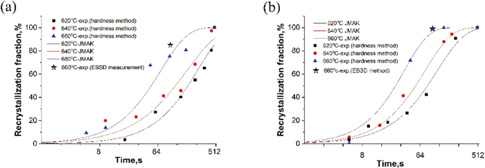
The JMAK model is used to describe the recrystallization kinetics.7,8)
where
k and
n are fitting parameters. The original data and the fitted curves are shown in
Fig. 7. It can be seen that the time required for complete recrystallization is remarkably shorter for the B steel. The fitted parameters
k and
n are listed in
Table 3. The exponents
n for the recrystallization of the FP and B steel are around 1.0, close to the values reported in the literature for the recrystallization of cold rolled steels.
8)
Table 3.
k and
n values for two steels.
| T/°C | FP steel | B steel |
|---|
| k | n | k | n |
|---|
| 620 | 0.0026 | 1.06 | 0.0077 | 0.93 |
| 640 | 0.010 | 0.88 | 0.010 | 1.04 |
| 660 | 0.011 | 1.05 | 0.016 | 1.15 |
The recrystallization kinetics was analysed according to the usual Arrhenius-type equation:
|
ln
t
0.5
=ln
t
0
+
Q
act
/RT
| (3) |
where
t0.5 is the time to reach 50% fraction of recrystallization,
t0 is the pre-exponential factor,
Qact is the activation energy for recrystallization,
R is the gas constant and
T is the absolute temperature. From the linear segments of the plots of ln
t0.5 versus 1/
T the activation energies for FP and B steel are estimated to be 232 kJ/mol and 207 kJ/mol, respectively. The activation energy of FP steel is close to that for the self-diffusion of iron, but for B steel, the activation energy is markedly lower. Yang
et al.7) studied the ferrite recrystallization of a cold rolled ferrite-pearlite steel, and found that the activation energy was reduced from 272 to 226 kJ/mol as the cold rolling reduction increased from 25% to 50%. In Etesami’s research,
10) it was also found that the activation energy drops to 125 kJ/mol for a cold-rolled ferrite-martensite steel with a cold rolling reduction of 80%. The reduced activation energy for recrystallization in the cold-rolled B steel was attributed to the higher initial dislocation density.
4.2. Austenite Formation in FP Steel
As is generally accepted, during heating of a ferrite-pearlite steel, austenite nucleates preferentially on the ferrite-cementite interface followed by subsequent austenite growth into the pearlite.8) The thermodynamic driving force for the nucleation of austenite at the ferrite-cementite interface, DFN can be written as:
|
D
F
N
=
μ
Fe
α/θ
-
μ
Fe
γ/N
=
μ
c
α/θ
-
μ
c
γ/N
| (4) |
Where μFeα/θ and μcα/θ is the chemical potential of Fe and C at the α/θ interface, respectively, and μFeγ/N and μcγ/N is the chemical potential of Fe and C corresponding to austenite nucleation, respectively.
For the case of fast heating, a higher dislocation density would be retained at the onset of austenite nucleation. Accordingly, Gibbs energy of ferrite would be higher compared to that with lower defect density, i.e. at slow heating. In this scenario, the driving force DFN will increase from ΔG0 to ΔG0’ as shown in Fig. 8. On the other hand, under these conditions austenite formation on the ferrite/ferrite boundaries may also be thermodynamically possible due to the enhanced Gibbs energy of ferrite, in which case the austenite formation may occur in a massive manner,24) i.e. austenite can transform from ferrite with the same carbon concentration with a driving force of ΔG1 (Fig. 8). Both phenomena contribute to an enhanced austenite nucleation under conditions of fast heating.

As shown in Fig. 4(b), for samples treated with a slow heating rate of 5°C/s, recrystallization is incomplete before austenite nucleation starts. In this case, austenite forms preferentially on ferrite-pearlite boundaries similarly as in Fig. 4(a). Laterally, it also forms on the recrystallized ferrite-ferrite boundaries. This suggests that the uniformity of the FP steel can be increased through increasing the proportion of ferrite recrystallization before austenite transformation. In addition, it is found the banded martensite is larger than the martensite formed in the grain interior. This is due to the abundant carbon supply from the cementite bands as well as the locally higher Mn concentration, which leads to a lower Ac1 temperature so that austenite will form earlier and grow to a larger size.
For REX processing, cementite particles are located at the former position of the pearlite while the ferrite is recrystallized. Due to the ferrite grain boundary movement during recrystallization, some of the cementite particles now lie inside the ferrite grains. In order to investigate the preferential nucleation position of austenite, interrupted quenching experiments were carried out in which the specimen was heated to a temperature just 5°C higher than Ac1 temperature. An optical micrograph of the microstructure obtained is shown in Fig. 9(a). It is found that austenite (corresponding to the locations of the martensite) nucleates preferentially on the cementite bands which are aligned with the ferrite grain boundaries in the rolling direction. Very few nuclei were found inside the ferrite grains even though there are rows of cementite particles. In addition, the “clean” ferrite boundaries that are free of cementite (as shown with white arrows) are hardly occupied by austenite. Therefore, the preferred nucleation sites in this case are the junctions between the cementite and the ferrite grain boundaries.13,25) While those ferrite boundaries far away from cementite can only be invaded by austenite following long range carbon supply by cementite dissolution. The smaller size of these martensite particles on ferrite grain boundaries perpendicular to rolling direction (shown with dotted arrows in Fig. 4(c)) supports the delayed nucleation hypothesis.

Figure 10(a) shows the austenite fraction for the three heating routes explored. The transformation kinetics are considerably affected by the prior heating rate, i.e. increasing the heating rate accelerates the transformation kinetics. The higher heating rate will leave a higher stored energy in ferrite which increases the driving force for austenite nucleation and growth.12,13,26) Chbihi et al.12) reported that for high heating rates austenite grows under a condition close to PE (para-equilibrium) at the beginning of the transformation. And another reason is that the accelerated C and Mn diffusion due to the higher dislocation density. The work by Dmitrieva et al.27) also supports the assumption of a higher Mn mobility. In case of REX processing, the austenite formation kinetics is decelerated due to the lower driving force for austenite formation as well as the lower diffusivity of C and Mn.
4.3. Austenite Formation in B Steel
For the B steel, the austenite nucleation conditions may be different as a high defect density would be preserved in particular during fast heating. Thus, as is shown in Fig. 11, the Gibbs free energy Gα’ is higher. Moreover, some supersaturated carbon would be trapped in the matrix. When the heating rate is high enough, there is not enough time for cementite precipitation. And thermodynamically, driving force for nucleation of cementite can be lower than that of austenite, i.e. ΔGθ < ΔG1’. In this respect, austenite can be transformed with the same composition of the matrix, i.e. the nucleation of austenite occurs with a massive-like manner.28,29)

Cementite precipitates uniformly in the matrix after recrystallization (Fig. 3(d)). Optical micrograph of the specimen which was treated for 100 s at 660°C followed by heating to a temperature just 5°C higher than Ac1 temperature and immediate quenching is shown in Fig. 9(b). It is found that austenite nucleated preferentially on the ferrite grain boundaries. However, it is reported that austenite nucleating on a ferrite α/α grain boundary is thermodynamically unlikely because of the lack of carbon.24) Hence, it is assumed that the austenite nucleated on those ferrite grain boundaries which were decorated by submicron cementite particles. As in the case of the FP grade, recrystallized ferrite grain boundaries that are free of cementite (as shown with white arrows) can only be occupied by austenite in case of dissolution of cementite inside ferrite grains or segregation of solute carbon towards ferrite grain boundaries. Generally, austenite preferentially nucleates at ferrite-cementite interface on ferrite boundaries rather than inside ferrite matrix.30)
The austenite fraction for the isothermal holding process of the B steel starting structure is also shown in Fig. 10(a). The austenite fraction follows the trend of 100°C/s > 5°C/s > REX processing, similar to the order observed for the FP grade. It is found that, for the same heating conditions, the austenite fraction of B steel is slightly higher than that of FP steel. The reason is considered to be the increased nucleation sites resulted from the refined microstructure as well as enhanced defect density in B steel. Interestingly, it is found that the austenite fraction increases more sharply in the early stage in the case of high heating rate for FP steel. As can be seen in Fig. 10(b), the transformation rate at the early stage is higher in FP steel but it decreases and tends to be close for both steels after a few seconds. Compared to the B steel, for the FP steel the austenite can grow quickly by thickening and lengthening in pearlite colonies because of the short-range carbon redistribution.8) In Fig. 10(b), both transformation rate curves tend to coincide after 2 s, and the corresponding austenite fraction is 0.28 at this time in FP steel, which is close to the initial pearlite fraction of 0.25 as can be calculated from Fig. 2(a). It means that austenite transformation rate would slow down and be close to that of B steel once the pearlite colonies are consumed by the austenite.
4.4. Influencing Factors of BR
Figure 12(a) shows the relationship between BR and TEL. The figure shows that for the same initial microstructure, BR increases linearly with TEL. However, once the initial microstructure changes from FP to B steel, the BR is at a much higher level. Especially, for the B steel, the BR is comparable to that of slow heating even though the TEL is remarkably reduced. Thus, it can be concluded that there is no simple linear relationship between total elongation and bendability, as reported in other studies.31,32)

In some studies, the hardness difference between the soft and hard phase is thought to affect the void nucleation, growth and the failure behavior during bending or hole expanding through the strain localization. In Taylor’s study,1) a smaller ferrite/martensite hardness ratio is reported to bring a higher degree of strain partitioning to the softer ferrite phase, potentially inducing more damage to the matrix. Hasegawa et al.32) presented a linear relationship between hardness difference of martensite/ferrite and hole expansion ratio. Assuming that the yield strength is determined by ferrite hardness and that tensile strength is determined by martensite hardness, yield ratio (YR) was calculated to represent the ferrite/martensite hardness ratio. Fang et al.33) also reported that a high YR corresponds to a good hole expansion behaviour, i.e. a strong ferrite is favourable for hole expansion. It is shown in Table 2 that for the same heating route, YR is about equal for the FP and B steels while BR varied significantly for the similar YR, e.g. FP-1/B-1, FP-2/B-2 and FP-3/B-3. Thus, the reported relation between yield ratio and bendability is not confirmed in this study.
It is shown that a major microstructural difference between the FP and B steel grades lies in the spatial distribution of martensite. In the FP steel, the martensite is distributed according to the characteristics of the perlite banding due to the microstructure inheritance even though it can be alleviated through the REX pre-treatment. On the other hand, in the B steel, the martensite is distributed uniformly. A number of researches have been carried out on the failure behaviour for different martensite distribution. Ramazani et al.34) found that failure initiation occurs in banded martensite at lower plastic strains and considered martensite cracking as the main failure mechanism. Tasan et al.35) reported that shear bands would form in case of bending and they would percolate the banded martensite, causing early damage initiation. Yamazaki et al.19) also reported that the bendability of 980 MPa DP steel is not related to total elongation but to microstructural homogeneity.
The anisotropy index (AI), which characterizes the homogeneity of the distribution of the second phase was evaluated for FP and B steel according to ASTM E1268-19. In this method, the degree of banding is quantified using a statistical analysis of the topological patterns of digitized microstructural images of alloys containing two distinguishable phases, essentially relating the summed length of the intercepts of the distributed phase in the rolling direction to that in the perpendicular direction. The relationship between BR and AI is plotted in Fig. 12(b). The BR decreases with the increase of the AI of the same steel grade. When combining the data from both grades, still the BR decreases as the AI increases, which means that an enhancement of uniformity in martensite distribution indeed leads to a higher bendability. However, the encircled data points show that this relationship is not obeyed strictly. Figure 12(c) shows the BR versus TS. For the same initial microstructure, BR decreases linearly with the increase of TS. However, the BR was improved integrally once the initial microstructure changes from FP to B steel even with similar TS. There is thus no simple monotonous relationship between tensile strength and bending ratio.
Finally, we explored whether there is a relationship between BR and product of TS and AI. Figure 13 shows the data for Log (BR) versus Log (TS*AI). One can see that there is a decent linear relationship. The equation that fits these data is Log (BR) = 1.159−0.41 Log (TS*AI). In order to further validate this correlation, data from the literature14) including the TS, BR and AI (calculated according to SEM micrographs) for other DP steels but having a different chemical composition and slightly different bending conditions were extracted. These data are also plotted in Fig. 13 and again a linear relationship is observed. Thus, it is proposed that the bending ratio is determined by the microstructure distribution as well as by the strengthening factors. Generally, strength is mainly affected by grain size and martensite volume fraction for certain chemical composition in DP steel.3,4) Therefore, it can be concluded that the bendability of DP steel is determined by the combined structural parameters, such as grain size, volume fraction as well as spatial distribution of martensite.

5. Conclusions
In this study, the effect of initial microstructure on ferrite recrystallization as well as combined effect of start microstructure and heating route on austenite formation kinetics and martensite distribution was elucidated. The main conclusions from this work are as follows:
(1) Ferrite recrystallization kinetics is accelerated in the cold-rolled bainitic steel compared to ferrite-pearlite steel. The main reason for a lower activation energy in the former one due to the higher defect density. Different initial microstructures (e.g. distribution of carbon), yield distinctly different cementite particle distributions.
(2) The junctions between cementite and ferrite grain boundaries are preferred nucleation sites for austenite. While, those ferrite boundaries far away from cementite can only be invaded by austenite through carbon supplying by cementite dissolution or carbon segregation towards ferrite grain boundaries. The smaller size of martensite particles on ferrite grain boundaries for REX processing in FP steel supports the delayed nucleation hypothesis.
(3) An in-line recrystallization step in the thermal route can alleviate the banding severity in FP steel by supplying more ferrite grain boundaries but it does not eliminate banding. Given the uniform distribution of cementite after ferrite recrystallization in the B steel, austenite preferentially nucleates on recrystallized ferrite boundaries, leading to a homogeneous distribution of martensite.
(4) Due to the enhanced driving force under high heating rate, nucleation of austenite can occur with a massive-like manner and austenite transformation kinetics is significantly accelerated.
(5) Bendability rather than strength-ductility combination can be significantly improved by a more uniform distribution of martensite. The bendability of DP steel is determined by the combination of microstructural parameters, in particular the martensite distribution, and the mechanical properties as measured in uniaxial tensile testing.
Acknowledgements
This study is supported by the National Natural Science Foundation of China (Grant No. 51774082, Grant No. 51774083), National Key Research and Development Program (Grant No. 2017YFB0304402) and by the China Scholarship Council (201706085039).
References
- 1) M. D. Taylor, K. S. Choi, X. Sun, D. K. Matlock, C. E. Packard, L. Xu and F. Barlat: Mater. Sci. Eng. A, 597 (2014), 431.
- 2) P. Li, J. Li, Q. G. Meng, W. B. Hu and D. C. Xu: J. Alloy. Compd., 578 (2013), 320.
- 3) P. H. Chang and A. G. Preban: Acta Metall., 33 (1985), 897.
- 4) M. Park, A. Shibata and N. Tsuji: MRS Adv., 1 (2016), 811.
- 5) L. Schemmann, S. Zaefferer, D. Raabe, F. Friedel and D. Mattissen: Acta Mater., 95 (2015), 386.
- 6) C. C. Tasan, M. Diehl, D. Yan, M. Bechtold, F. Roters, L. Schemmann, C. Zheng, N. Peranio, D. Ponge, M. Koyama, K. Tsuzaki and D. Raabe: Annu. Rev. Mater. Res., 45 (2015), 391.
- 7) D. Z. Yang, E. L. Brown, D. K. Matlock and G. Krauss: Metall. Trans. A, 16 (1985), 1385.
- 8) J. Huang, W. J. Poole and M. Militzer: Metall. Mater. Trans. A, 35 (2004), 3363.
- 9) A. Karmakar, M. Ghosh and D. Chakrabarti: Mater. Sci. Eng. A, 564 (2013), 389.
- 10) S. A. Etesami and M. H. Enayati: Metall. Mater. Trans. A, 47 (2016), 3271.
- 11) C. W. Zheng and D. Raabe: Acta Mater., 61 (2013), 5504.
- 12) A. Chbihi, D. Barbier, L. Germain, A. Hazotte and M. Goune: J. Mater. Sci., 49 (2014), 3608.
- 13) M. Kulakov, W. J. Poole and M. Militzer: Metall. Mater. Trans. A, 44 (2013), 3564.
- 14) G. Rosenberg, I. Sinaiová, P. Hvizdoš and L. Juhar: Metall. Mater. Trans. A, 46 (2015), 4755.
- 15) V. L. de la Concepción, H. N. Lorusso and H. G. Svoboda: Procedia Mater. Sci., 8 (2015), 1047.
- 16) N. Nakada, M. Tsukahara, K. Fukazawa and Y. Misaka: Mater. Trans., 59 (2018), 166.
- 17) K. Park, M. Nishiyama, N. Nakada, T. Tsuchiyama and S. Takaki: Mater. Sci. Eng. A, 604 (2014), 135.
- 18) G. Avramovic-Cingara, Y. Ososkov, M. K. Jain and D. S. Wilkinson: Mater. Sci. Eng. A, 516 (2009), 7.
- 19) K. Yamazaki, Y. Mizuyama, M. Oka, H. Tsuchiya and H. Yasuda: Nippon Steel Tech. Rep., (1995), No. 64, 37.
- 20) M. Kulakov, W. J. Poole and M. Militzer: ISIJ Int., 54 (2014), 2627.
- 21) G. Krauss: Metall. Mater. Trans. B, 34 (2003), 781.
- 22) S. E. Offerman, N. H. van Dijk, M. Th. Rekveldt, J. Sietsma and S. van der Zwaag: Mater. Sci. Technol., 18 (2002), 297.
- 23) H. Farahani, W. Xu and S. van der Zwaag: Metall. Mater. Trans. A, 49 (2018), 1998.
- 24) F. M. Castro Cerda, I. Sabirov, C. Goulas, J. Sietsma, A. Monsalve and R. H. Petrov: Mater. Des., 116 (2017), 448.
- 25) Q. Q. Lai, M. Gouné, A. Perlade, T. Pardoen, P. Jacques, O. Bouaziz and Y. Bréchet: Metall. Mater. Trans. A, 47 (2016), 3375.
- 26) M. Ollat, V. Massardier, D. Fabregue, E. Buscarlet, F. Keovilay and M. Perez: Metall. Mater. Trans. A, 48 (2017), 4486.
- 27) O. Dmitrieva, D. Ponge, G. Inden, J. Millán, P. Choi, J. Sietsma and D. Raabe: Acta Mater., 59 (2011), 364.
- 28) M. Yonemura, H. Nishibata, T. Nishiura, N. Ooura, Y. Yoshimoto, K. Fujiwara, K. Kawano, T. Terai, Y. Inubushi, I. Inoue, K. Tono and M. Yabashi: Sci. Rep., 9 (2019), 11241. https://doi.org/10.1038/s41598-019-47668-6
- 29) V. I. Zel’dovich: Met. Sci. Heat Treat., 50 (2008), 442.
- 30) Z. D. Li, G. Miyamoto, Z. G. Yang and T. Furuhara: Scr. Mater., 60 (2009), 485.
- 31) K. Choi, A. Soulami, D. S. Li, X. Sun, M. Khaleel, L. Xu and F. Barlat: SAE Technical Paper, 2012-01-0042, (2012). https://doi.org/10.4271/2012-01-0042
- 32) K. Hasegawa, K. Kawamura, T. Urabe and Y. Hosoya: ISIJ Int., 44 (2004), 603.
- 33) X. Fang, Z. Fan, B. Ralph, P. Evans and R. Underhill: J. Mater. Sci., 38 (2003), 3877.
- 34) A. Ramazani, Z. Ebrahimi and U. Prahl: Comput. Mater. Sci., 87 (2014), 241.
- 35) C. C. Tasan, J. P. M. Hoefnagels and M. G. D. Geers: Scr. Mater., 62 (2010), 835.