Review Article
Digital Twin Science of Metal Powder Bed Fusion Additive Manufacturing: A Selective Review of Simulations for Integrated Computational Materials Engineering and Science

2022 年 62 巻 11 号 p. 2183-2196

詳細
2022 年 62 巻 11 号 p. 2183-2196
A digital twin (DT) is a cyberspace replica of a system, such as manufacturing equipment. A DT consists of statistical models and computer simulations of physical phenomena occurring in the system. The modeling is adjusted to the system based on signals from sensors attached to the system and their temporal changes. In general, a DT is utilized to (i) predict phenomena occurring in the system, (ii) optimize control parameters, and (iii) estimate part replacement schedules. We propose to use a DT to elucidate the unique solidification phenomena occurring in a type of metal 3D printing (i.e., additive manufacturing: AM) process. Thus, we propose that applications of DT that obtain scientific data be referred to as “digital twin science (DTS).” This paper first reviews the fundamental of the AM process, particularly powder bed fusion (PBF) and relevant computer simulations, and then studies on computer simulations conducted to elucidate the relationship between the extreme conditions characteristic of the PBF process and solidification microstructures. The findings achieved by the DTS approach indicate that the combination of experimental and simulation data aid the future development of techniques to obtain required microstructures exhibiting desired properties.
In recent years, the digital transformation (DX) of manufacturing has been accelerating, as has the development of intelligent society, as reflected by the concepts of “Society 5.0” and “Connected Industries” introduced by the Japanese government as well as the Fourth Industrial Revolution (Industry 4.0) adopted worldwide after the introduction by the German government.1) These transformations are expected to realize a society in which the optimal materials and processes are designed from the required performance and functions by solving inverse problems, and products will be manufactured in the required place, time, and quantities. In such a society, manufacturing supply chains are resilient to environmental and circumstantial changes, such as natural disasters and international affairs changes. This trend has been further strengthened by the move toward the DX of society in the wake of infectious disease epidemics.2) Cyber-Physical Systems (CPSs) and digital twins (DTs) are being developed to realize such a society.1,3) CPSs are complex systems that integrate cyberspace (i.e., the world of digital information in computers and their networks) and the physical space (i.e., the real-world of materials, machines, and environment). DTs are cyberspace replicas of systems such as manufacturing apparatuses, factories, complex machine systems, climate systems, and logistic systems. DTs are constructed by statistical models (especially in macroscopic scales) and physical models (especially in microscopic scales). Computer simulations are used for physical modeling to reproduce physicochemical phenomena occurring in manufacturing facilities. CPSs and DTs are constructed on various scales.1,3,4,5,6,7,8,9,10,11) On the macroscopic scale, they are applied in areas such as weather forecasting,6) optimization of logistics networks for supply chains,6) and failure prognostic for parts replacement of machines.7,8,9,10,11)
In order to contribute to the development of manufacturing systems that can produce highly reliable customized parts, we conduct computer simulations that reproduce the various phenomena occurring in a digitally controlled additive manufacturing (AM) machine —that is, 3D printers—. Particularly, we aim to establish the DT for the powder bed fusion (PBF) process (Fig. 1),12) which is a mainstream technique for metal AM.7,13) In the DT of PBF, each process step is simulated by numerically solving various equations based on physical and chemical laws. First, the spreading behavior of powder particles during the raking process is simulated by the discrete element method (DEM),14,15,16,17,18,19,20,21,22,23,24,25) in which Newton’s equation of motion and Euler’s equations of motion for a rigid body for each particle are solved numerically to predict particle motion. Second, the heating of materials due to the beam-matter-interaction is computed. The temperature distribution is estimated by the finite element method (FEM) with a volumetric heat source model in simple models. For higher accuracy, more sophisticated models such as the ray tracing for laser-matter interaction26) and the Monte-Carlo method for electron-matter interaction27) are used. Then, the fluid flow in the melt-pool is predicted by the computational thermal-fluid dynamics (CtFD), in which the Navier-Stokes equation and Fourier’s equation are solved basically. Lastly, the microstructure formation and crystal growth during solidification are simulated by the phase-field method (PFM), in which the Cahn-Hilliard equation and Allen-Cahn equation are solved to evolve the distribution of solute and order parameters. The order parameters represent the status of atomic arrangements, such as crystal structure, crystal orientation, and degree of order depending on the material of interest. PFM is suitable for simulating the formation of microstructures with a relatively small length scale, such as dendrite structures which are typically smaller than 10 μm. The cellular automaton (CA) method can also be used for simulating microstructure. CA is more suitable for simulating microstructure formation with a relatively large length scale, such as grain structures for the whole area of a melt-pool28) and grain structures generated by superposition of melt region for multiple melt tracks.29) The results of these simulations are compared with the experimental data. Some of the parameters required for conducting computer simulations are then determined such that the simulation is consistent with the experiment. The values of the determined parameters are scientifically important information. They can provide clues to the discovery of new phenomena occurring in PBF. Therefore, we refer to the systematic application of a DT to obtain scientific data as “digital twin science (DTS).”

Concept of digital twin (DT) for powder bed fusion (PBF) additive manufacturing (AM) (DEM: discrete element method, CA: cellular automaton) (Reproduced from the web site of Koizumi Laboratory, Osaka University12)). (Online version in color.)
This review introduces some aspects of studies pertaining to the DTS of PBF of metals—focusing on computer simulations of the PBF process—and discusses future AM prospects. An analysis of existing studies reveals that the development of both experimental monitoring techniques and computational simulation is required to achieve an AM technology that realizes various technologies such as site-specific microstructure control, which can optimize the material properties of AM-build parts depending on the required properties at the location. In order to guarantee the desired material properties, it is needed to detect defects, correct the building conditions for eliminating defects, and achieve the required microstructures. DTS can facilitate the development of such technologies. The rest of this paper is as follows. Section 2 briefly discusses the fundamentals and characteristics of PBF, and Section 3 summarizes previously reported simulations of the PBF process. Section 4 discusses the challenges in this field and future research directions in the context of DTS. Finally, Section 5 concludes the paper.
PBF is typically applied to the fabrication of parts with the size ranging from several millimeters to several hundred millimeters. PBF is the AM process most applied to metals. In this technique illustrated in Fig. 2, the powder is spread on a flat metal plate called the “build platform” to create a powder layer called the “powder bed.” The powder bed is then irradiated with a laser or an electron beam scanned along the horizontal serial cross-sections generated by slicing the shape of the parts to be built in cyberspace, i.e., in a computer. The scanned beam melts the powder particles to form a dense material layer. After the beam scanning on a layer is completed, the build platform is lowered by the height corresponding to the thickness of the sliced layer. Then, a new powder bed layer is formed, followed by beam scanning along the horizontal cross-section slice of the upper layer at the height of one layer to fuse the powder particles within the layer and bond them to the layer below. This process is repeated to build the required 3D parts.
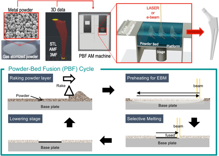
Schematic of PBF AM process (STL: stereolithography, AMF: AM format, 3MF: 3D manufacturing format). (Reproduced from the web site of Koizumi Laboratory, Osaka University12)). (Online version in color.)
The primary mechanism of PBF was developed at the University of Texas at Austin and initially applied to polymer powder heated by a CO2 laser.30) It has been applied to metals owing to the increase in available beam power.31) Initially, the method was called selective laser sintering (SLS) because the powder particles were sintered without melting. This is because the CO2 laser was not efficient in fusing metal powders owing to the low absorption efficiency of the laser power to metals. Therefore, the built parts obtained by SLS were porous, and the relative densities of the parts were no higher than 99%.32) Later, dense metal parts with almost no porosity with relative densities over 99% were obtained by completely melting the powder particles using high-power beams such as fiber lasers and electron beams. Hence, selective laser melting (SLM)33) and electron beam melting (EBM)34,35) techniques have been developed.33,34,35) The term “selective electron beam melting” (SEBM) is also used in the literature.34) The ASTM and the ISO agreed to use the term “fusion” rather than “melting” regardless of the beam type.36) The former reflects better the process characteristics as it indicates not only melting but also solidification and bonding. Hence, the process was named “powder bed fusion (PBF).” The acronym PBF-LB/M (LB: laser beams, M: metal) was defined for AM of metal parts by the PBF process using a laser as the heat source in the ISO 52900, which was revised in 2021.37) This review employs the widely used acronyms SLM and EBM to refer to PBF processes using a laser and an electron beam, respectively.
There are various computer simulations for the AM processes—particularly on the different manufacturing stages. These include simulations for (i) part design,38,39,40,41,42) (ii) determining the placement of multiple parts in the building space (i.e., build envelope), and (iii) the design of supports.43) There are also simulations for (iv) the analysis of residual strain caused by thermal stress,44) (v) the feeding of raw materials such as wire and powder, (vi) the process of melting and fusing the powder using LBs,45) and electron beams (EBs),46,47,48) and (vii) microstructure formation through crystal growth and phase transformation during solidification and subsequent cooling processes.28,48,49,50,51,52) Many process parameters must be used appropriately to produce sound build-parts, and computer simulations play significant roles. This section reviews simulations previously reported in the literature,53,54,55,56) focusing on the PBF process, the most widely applied AM process for metals.
3.1. Design and LayoutDesigning parts using computer-aided design (CAD) is the starting point of AM process, commonly in other digital manufacturing processes such as the machining centers, which represent computer-aided manufacturing (CAM). AM processes have a high degree of freedom to produce parts with shapes that are impossible to achieve through conventional processes such as cutting and molding because of the limitations due to tool access, material flow, and release after molding. Owing to the emergence of AM, design through structural optimization based on stress analysis simulation using the finite element method (FEM) (as represented by topology optimization methods developed in the 1990s) has attracted renewed attention. Commercially available software packages such as Altair OptiStruct57) and Quint OptiShape58) have been developed as CAD software modules. Software packages, such as Ansys Additive Suite,59) also contain modules for shape optimization together with other modules for generating support and analyzing thermal stress.
In the past, even if structural optimization could be performed to design a customized part, its fabrication using conventional technology was often impossible owing to the above-mentioned limitations. AM technology has made it possible to manufacture almost any arbitrarily shaped components, and this capability has significantly increased the use of structural optimization calculations.52,53,60,61,62,63,64,65)
Figure 3 shows an example of the structural optimization of a cellular lattice porous material conducted by the present authors.53) In that study, the stress distribution was evaluated under uniaxial loading in the unit cell model (Fig. 3(a)) via FEM and performed structural optimization to reduce the maximum local stress and improve the structural strength while reducing Young’s modulus of the entire structure by 2/3 (Fig. 3(b)) or increasing it by 3/2 (Fig. 3(c)). The optimized cellular lattice porous material was physically fabricated through EBM with a Co–Cr–Mo alloy for biomedical applications (Figs. 3(d)–3(f)). The stress-strain behaviors were measured as in Fig. 3(g). The curves for other designs exhibited clearly different stress-strain responses. The results were reproducible since the three curves for each case were nearly the same. Figure 3(h) shows the balance between the strength and Young’s modulus of fabricated cellular materials. They exhibited roughly the designed characteristics, but there were non-negligible deviations. These deviations occurred because the material properties were assumed to be isotropic and uniform in the optimization calculations; however, they are anisotropic because of the crystalline orientation textures and their inhomogeneity, as shown in Fig. 4. Hence, the AM process needs to control the crystalline orientation during fabrication.

(a–c) Unit cell models and (d–f) cellular lattice porous structures: (a, d) before and after optimization with Young’s modulus adjusted to (b, e) 2/3E0 and (c, f) 3/2E0, respectively. The colors indicate the von Mises stresses under compression to a strain of 2 ×10⁻⁵ in the z-direction, (g) Stress-strain curves of the cellular lattices, and (h) the balance between Young’s modulus and yield strength (after Koizumi et al.,53) reproduced with permission from Elsevier). (Online version in color.)

Electron backscattering diffraction phase map and inverse pole figure (IPF) orientation maps obtained at node and strut of Co–Cr–Mo alloy cellular lattice structure fabricated via electron beam melting (after Koizumi et al.,53) reproduced with permission from Elsevier). (Online version in color.)
Currently, increasingly sophisticated optimization software is being developed commercially66) and academically.67) For example, simulation technology has been developed to design custom-fit implants based on 3D shape data of a patient’s bone obtained via X-ray computed tomography (CT) or magnetic resonance imaging (MRI). In AM, the building time and accuracy depend on the arrangement and orientation of the objects to be built, even for manufacturing the same part. Defects are likely to form on the underside of the object in the so-called “overhang,” where there is no support from below.68,69) The formation of the defect is avoided by the concurrent fabrication of a temporary support member below the overhang parts. Simulations to automatically design such supports have been developed.68,69) Recently, the digital twin approach for topology optimization has been demonstrated. The sensor signals of the actual force generated during practical use were used to design an arbor press with reduced material use by topology optimization.70)
3.2. Powder Flow ProcessUnderstanding, predicting, and controlling the powder flow are essential to avoid defects in objects built by the PBF process. Empirically, powders with high sphericity and narrow particle size distributions are suitable for forming a uniform powder layer; however, the reasons for this are not fully understood. This uncertainty of the mechanism is because the powder bed forms beneath other powder particles, making it challenging to observe the behavior of powder particles experimentally. The discrete element method (DEM) is a computer simulation method that can model the behaviors of such powders,14,15,16,17,18,19,20,21,22,23,24,25) as it numerically analyzes the motion of each particle according to Newton’s equation of motion and Euler’s equation of motion by calculating the viscoelastic and frictional forces acting between the particles. This method has been developed in various studies of phenomena relevant to a massive number of particles, such as sediment flow, ball milling of powders, silo filling, powder mixing,72) and the behavior of slag particles in submerged arc welding.73) The DEM technique has also been applied to the analysis and optimization of powder layer formation in the PBF process.21,22,23)
Figure 5 shows snapshots of the simulated powder layer formation in PBF-EB, in which powder particles were raked into a recess with a depth close to the powder particle size.23) Figure 6 shows an example of the effect on the degree of powder-layer filling for the case where the frictional force governing the powder flowability was hypothetically changed. For a low frictional force and high flowability (Fig. 6(a)), the powder particles were dispersed and filled the layer evenly. However, as the frictional force was increased, the powder particle distribution became uneven, forming large areas without powder particles (Figs. 6(b), 6(c)). These results correspond to the fact that powders that are not spherical or attached to satellite particles have low flowability, thereby increasing the difficulty of forming a powder bed. Importantly, this outcome validates DEM in predicting powder bed formation ability from powder properties. Here, it should be noted that the comparison of the simulation results and experiments is crucial from the point of view of DTS. For conducting DEM simulations, an appropriate model needs to be selected or developed depending on the characteristics of powder particles. In general, the Herz-Mindlin (H-M) contact model is employed for describing the inter-particles interaction. In the H-M contact model, the repulsive force and the damping between colliding particles are modeled by springs, dashpots, and sliders with properties appropriate for reproducing the fundamental collective behaviors of the powder, such as the static angle of repose, dynamic angle of repose. It is not straightforward to determine the parameters since the angles are determined as the results of the combination of several parameters representing the interparticle interaction, the sphericity of particles, and so on. Even when the angles are close to the experimental ones, the values of the parameters are not necessarily correct if there exists an interaction that is not taken into account. The method for the determination of the parameters is still to be established. Nevertheless, it is worth conducting the DEM simulations from both scientific and engineering points of view. If the difference between the experiment and the computer simulation is negligible, the simulation results can be used not only for predicting the effect of change in the process condition but also for a deep understanding of the behavior of individual particles, which are difficult to observe experimentally. If the difference is significant, the existence of unrecognized interparticle forces is implied.

Snapshots of DEMsimulation for the formation of powder bed (after Y. Zhao et al.,25) reproduced with permission from Elsevier). (Online version in color.)

Powder layer patterns obtained for varied flowability, as indicated by resultant powder repose angles: (a–c) high, medium, and low flowability, respectively; (d) highly magnified image of layer pattern obtained with high flowability (after Y. Zhao et al.,25) reproduced with permission from Elsevier). (Online version in color.)
More recently, we showed—by both DEM simulation and experiment—the effect of particle size on the powder distribution in the powder bed for a given gap between the base plate and the bottom of the rake blade, as presented in Fig. 7. The trends in the distribution of powder particles are qualitatively reproduced by DEM simulation. However, there are non-negligible differences between the simulation and experiment in the quantity of filling ratio (i.e., the ratio of area fraction of the surface occupied by powder particles). Further detailed investigation with the DTS approach will provide more quantitative information and a deep understanding of the effects of powder particle quality, including the influence of satellite particles. Such a model to treat particles with satellites is now being developed.

Comparison between (a) experiment and (b) DEM simulation examining the effect of powder size on the distribution of powders in powder bed for a given gap between the base plate and the bottom of rake blade. (after M. Okugawa et al.,24) reproduced with permission from Japanese Society of Powder and Powder Metallurgy). (Online version in color.)
Some PBF-LB/M machines are equipped with a rolling tool for spreading powder feedstock. Figure 8 shows an example of a DEM simulation of powder spreading by a rolling tool.21) The DEM simulations have been used to investigate the effects of various factors which affect the quality of powder bed, such as properties of powder particles (e.g., sphericity, rolling friction, size distribution, adhesive force, etc.), conditions for the powder spreading process (e.g., the height of gaps between the blade and the surface of base-plate or the top surface of parts being built, speed of motion of spreading tool, the direction of rotation). The DEM simulation is helpful in understanding the behavior of powder particles because it is possible not only to analyze the motion of individual particles but also to analyze the statistical relationships among the powder particles. Moreover, it is possible to elucidate the strong interaction between powder particles by the detailed analysis of the difference between experimental results and DEM simulation.

DEM simulation of powder spreading using a cc rotating roller as a spreading tool. (after M.Y. Shaheen et al. Powder Technology 383 (2021) 564–58323) published by Elsevier. Reproduced under CC BY license). (Online version in color.)
In the PBF metal AM process, the production sequence involves the repeated melting of metal powders using LBs or EBs, densification by the flow of the melt to fill the open spaces, and solidification. Insufficient melting or unstable flow can leave voids after solidification, which can cause defects. Computer simulations to predict and avoid the formation of such defects have been reported by several groups. For example, Körner et al. at Friedrich-Alexander-Universität Erlangen-Nürnberg (FAU) in Germany previously predicted densification using CtFD that implements the lattice Boltzmann method.18,74,75,76,77,78,79) To reduce the computational cost, they performed a 3D simulation of the local melting behavior of a single powder layer in a small area. In addition, they simulated the densification of a multi-layered object using an approximate model in which the object was represented in 2D, and only the heat source was treated in 3D. They then created a process map showing the range of conditions under which dense bodies could be obtained. Similarly, Khairallah et al.45,80,81) at Lawrence Livermore National Laboratory in the US used a supercomputer for CtFD to simulate powder melting behaviors in the PBF-LB process; hence, they analyzed the underlying mechanisms of phenomena that causes defects, such as balling, denudation, and spattering. Their studies further demonstrated that the flow due to the non-uniformity of surface tension arising from the steep temperature gradient along the surface of the melt-pool (i.e., Marangoni flow) and the recoil pressure considerably impact the behavior of molten metals. Thus, CtFD simulations provide us with valuable insights into the behavior of molten materials in the PBF process. This is the typical case where the DTS is useful for elucidating the physics of PBF.
King et al.45) demonstrated that the absence of surface tension results in an unrealistic melting behavior of powder particles, as seen in the computer simulation (Fig. 9). Discontinuous and irregularly shaped beads are formed in the case where the surface tension is neglected, whereas a continuous melt-region (i.e., bead or melt-track), similarly to that observed experimentally, is formed (Fig. 9(a)) in the case with surface tension taken into account. Thus, the effect of the properties of molten metals (e.g., surface tension, viscosity, and their temperature dependences) must be considered for optimizing the process condition for fabricating new materials and designing new materials suitable for fabrication by the PBF process.

Laser tracks formed by laser irradiation on steel powder bed simulated by (a) with and (b) without surface tension. Color scale indicates temperature from the minimum of ambient (blue) to the maximum of steel melt temperature (red). The powder bed is 1 mm long, 200 μm wide, and 35 μm thick, with 100 μm thick substrate (after King et al.45) Reproduced with permission from Taylor and Francis). (Online version in color.)
Figure 10 shows the conceptual image of multiscale modeling of melting and solidification in the PBF process. The results of CtFD simulation are used as the boundary condition for the phase-field (PF) simulation of crystal grain growth during directional solidification. Currently, only the CtFD simulation and the PF simulation are coupled in only one way (i.e., weak coupling from CtFD to PF) in our study. The weak coupling can simulate the growth of columnar crystal grains. However, it is not sufficient to simulate the effects of the fragmentation of dendrite which affects fluid flow by convection. In the future, it will be required to establish a model with the strong mutual coupling of CtFD and PF for simulating the solidification phenomena taking place in the actual PBF process, in particular, the formation of equiaxed grains due to Marangoni convection. For the PF simulation, the parameters representing the characteristics of the materials are required. Boundary mobilities are generally unavailable from the existing databases, whereas solute mobilities are found in the database for the simulations of phase transformation, whose rate is controlled by solute diffusion. The evaluation of boundary mobility by molecular dynamics simulation is of great interest for PBF-process. The high solidification rates of the PBF process are considered to give rise to non-equilibrium solidification with less partitioning of solute atoms.

An image showing the concept of multi-scale modeling of PBF, consisting of computational thermal-fluid dynamics (CtFD) simulation, phased field simulation, and molecular dynamics. (Reproduced from the web site of Koizumi Laboratory, Osaka University12)). (Online version in color.)
The simulations for the densification prediction described above are helpful in predicting and avoiding the formation of defects such as pores. However, the properties of the formed object strongly depend on the internal microstructure and macroscopic defects. Importantly, if the object microstructure differs from that obtained through the conventional process, the properties also differ. If these properties are lacking, then the built object cannot be in practical use. Conversely, there are processes that yield properties superior to those obtained through the conventional process. Materials that exploit these properties, especially anisotropic materials that exhibit superior strength in a particular direction, are under active development.82,83,84,85,86,87,88) With regard to the strength of components, especially isotropic materials that can be obtained through conventional processes, the design assumes that the end material will exhibit isotropic properties. Therefore, conditions that yield an isotropic microstructure along with isotropic properties following the AM process are sought after. In particular, the use of crystal orientation to obtain single-crystal structures is being investigated. This aims to produce artificial joint implants with an elastic modulus close to that of bone86) as well as turbine blades with excellent creep resistance.87)
The microstructure obtained in the metal PBF process is solidified and considered to be determined by the combined influence of the temperature gradient at the solid-liquid interface (G) and the solid-liquid interface migration velocity (R). Construction of a solidification map (Fig. 11) based on the columnar-equiaxed transition (CET) criteria of Hunt89) has been proposed, which is then used to predict the microstructure or derive the conditions under which the desired microstructure can be obtained.89,90,91,92,93,94) Computer simulation is indispensable for constructing a solidification map and controlling the corresponding microstructure based on the CET by optimizing the fabrication conditions. For the latter, simulation is necessary because it is currently impossible to evaluate the values for the two axes of the solidification map, i.e., G and R for the PBF process.

Typical solidification maps for microstructure control based on the Hunt columnar equiaxed transition (CET): (a) conventional and (b) extended solidification maps with data points from Miyata et al.99) for EB-melt 316L SS. (Online version in color.)
Nevertheless, it is possible to measure the temperature distribution on the surface of the molten pool using remote temperature measurement methods, such as high-speed infrared cameras95) or two-color pyrometry methods.96,97,98) However, it is not currently possible to measure the time variation in the G and R, which determines the solidification microstructure. Therefore, the temporal change in the temperature distribution on the measurable surface must be evaluated through simulations consistent with the experimentally measured values.
FEM simulation is the most commonly used computational method for evaluating G and R at the liquid/solid interface.91,92,93,94) By solving the heat conservation equation, incorporating the temperature rise due to the heat input from the LB or EB and the cooling due to thermal diffusion, the temporal change in the temperature distribution can be obtained. In detail, G can be obtained as the spatial derivative of the temperature on the isosurface at temperature T = Tm (Tm: melting point) if the undercooling is not so significant. The value of R can be obtained directly by tracking the isosurface at T = Tm and determining the velocity. In practice, R is determined indirectly by evaluating the cooling rate dT/dt [K/s] from the temperature immediately above the melting point to the temperature immediately below the melting point, and then using the relationship between G [K/m], R [m/s], and dT/dt [K/s]. That is,
| (1) |
| (2) |
The accumulation of large volumes of data from such direct problem analysis enables the derivation of the fabrication conditions that give the desired material microstructure. This is an inverse problem in which (i) the solidification conditions that yield the desired microstructure are sought; (ii) the fabrication conditions under which such solidification conditions occur are obtained; and (iii) the process parameters for fabricating a part with the desired material properties are determined based on the derivation of the required material microstructure from the database of the relationship between the material microstructure and material properties. This approach is expected to yield AM technology that simultaneously controls the shape and material properties of the fabricated part.
The present authors are promoting research in which experiments and computer simulations are combined to produce a solidification map using the following procedure:
(I) A bulk of metal with a flat surface is irradiated with an LB or EB under various conditions (P, V) for melting and solidification, and the obtained microstructure is observed.
(II) Computer simulations of the melting and solidification process under the same beam conditions are conducted to evaluate the G and R distributions throughout the entire melt region through solidification by successively evaluating the G and R distributions along with the moving solid-liquid interface.
(III) The points corresponding to the pairs G and R at each position in the melted bead are marked on the G–R plane. The points are classified according to the experimentally observed microstructures at the corresponding position. Then, the G-R space is divided into regions where the microstructures of the same type (equiaxed or columnar) are obtained.
In a recent analysis of temperature distribution variations, which was performed using CtFD instead of the FEM process, the flow velocity caused by the Marangoni effect was found to affect the solidification microstructure strongly.55,99)
Zhao et al.55) demonstrated that the Marangoni effect is very significant in their study on EB melting of Co–Cr–Mo alloy by comparing the two CtFD simulations with and without the Marangoni effect. The effect can give rise to the convex melt-pool surface even in a vacuum where the recoil pressure is negligible. Figure 12 shows the snapshots of meltpool simulated by CtFD for the case of EB-irradiation on a bulk of 316L stainless steel.99)

Snapshot of CtFD simulation of electron-beam irradiation on 316L SS with process parameters of P = 1200 [W] and V = 100 [mm/s]. (a) Bird’s eye view, (b) side view on the vertical cross-section along the center of the scanning line. The color indicates the temperature (after Y. Miyata et al.,99) Reproduced under the CC-BY license). (Online version in color.)
Figure 13 shows the cross-sections of melt pools colored by solidification conditions. Solidification times (Figs. 13(a1)–13(c1)) indicate that the solidification starts at the region nearby the fusion line toward the center of the melt pool. In 316L SS, the G is highest in the regions near the fusion line and decreases as the solid-liquid interface moves toward the center of the melt pool (Figs. 13(a2)–13(c2)). On the other hand, the R is lowest near the fusion line and becomes higher as the interface approaches the center of the melt region (Figs. 13(a3)–13(c3)).

CtFD simulated cross-sectional melt pools of 316L SS colored by (a1–c1) a solidification time, (a2–c2) a temperature gradient, G, (a3–c3) a solidification rate, R, and (a4–c4) a flow velocity, U. The electron beam was scanned to the x-direction. The beam powers were (a1–a4) P = 600 [W], (b1–b4) P = 900 [W], and (c1–c4), P = 1200 [W] (after Y. Miyata et al.,99) Reproduced under the CC-BY license). (Online version in color.)
Figure 14 shows the cross-sectional EBSD orientation map (Fig. 14(a)) indicating the crystal orientation in z-direction (corresponding to the building direction in PBF process) of the bead formed by electron beam with P = 1200 [W] and V = 100 [mm/s], and the corresponding flow velocity distribution map (Fig. 14(b)). Equiaxed crystalline grains were observed near the outmost part of the melt region. According to Hunt’s CET criterion, a high G in the solidification front is preferable to a low G for forming columnar grains. On the contrary, the relationship between the microstructures and solidification conditions observed in 316L SS is contrary to that predicted by the CET criterion. In the welding process,100,101) equiaxed grains are reported to be formed owing to the effect of fragmentations of dendrites and the transport of the fragments. These results suggest that equiaxed crystal grains are formed owing to the effect of fragmentations of dendrites and the transport of the fragments also in the PBF-AM process, even though the G and the R are in the range for columnar grain formation. A similar trend has been reported for Co–Cr–Mo alloy.55)

Comparison of (a) solidification microstructure (EBSD IPF map) of melt region in 316L SS formed by scanning electron beam and (b) a corresponding snapshot of CtFD simulation colored by fluid velocity. (after Y. Miyata et al.,99) Reproduced under the CC-BY license). (Online version in color.)
Acquisition of data on the solidification microstructure through experimental observation is practical, as mentioned above, at this moment. Nevertheless, it is anticipated that the data acquisition of the microstructure formation through computer simulation is becoming practical as well. The latter can be performed using techniques such as cellular automaton (CA)28,29,102) and phase-field (PF) methods.46,103,104) According to the author’s best knowledge, Gong et al.46) performed PF simulations of microstructure formation for solidification in AM process for the first time. In their study, FEM simulation was used to evaluate the temporal change in the temperature distribution in a Ti-6Al-4V alloy irradiated with an EB. Then, they simulated the dendrite growth associated with the temporal change of temperature distribution.46) They demonstrated that the solidification microstructure significantly depends on the temperature distribution which can be changed greatly by changing the EB irradiation conditions. In that study, the range of solidification rates included was relatively small. Solidification of the Ti-6Al-4V alloy occurs through the growth of the β-phase from the liquid phase, followed by the precipitation of the α-phase. Therefore, the solidification behavior has a significant effect on the alloy microstructure and material properties, and the implications of the reported calculations are unclear. Actually, Gong et al.46) noted the need for simulations under conditions with higher cooling rates.
Recently, a group from RWTH Aachen University and Fraunhofer Institute for Laser Technology, Germany, investigated the solidification of Inconel 718 alloy during the PBF process using the PF method.103) Using the MICRESS PF simulation software developed by Access e.V. (Germany) and the thermodynamic database for Ni-based alloys (Thermo-Calc, Ni-Data version 8), they showed that the rapid solidification under a strongly non-equilibrium condition for G = 2 × 10⁷ s [K/m], R = 0.04 [m/s], and a cooling rate of 8 × 10⁵ K/s yielded cellular-like solidification without secondary dendrite arm formation. Here, the definitions of cellular growth and dendritic growth need to be mentioned. Cellular structures are formed as a result of constitutional undercooling. The fluctuation of the growth front enhances the protrusion since the constitutional undercooling at the tip (i.e., liquid side) of the fluctuated interface is higher than that at the bottom of fluctuation even though the actual temperature is higher than at the bottom. The direction of the protrusion is not defined by crystal orientation for cellular structure.
On the other hand, dendrite growth is associated with the anisotropic crystal growth toward the preferential growth direction, typically <100> direction for cubic crystals. The direction is determined by the combination of anisotropies of the energy and the boundary mobility of the solid/liquid interface. When the direction of the temperature gradient is parallel to the preferential growth direction, it is challenging to distinguish cellular structure from dendrite structure. (Dendrite can be easily identified if there are secondary arms.) According to the definition mentioned above, a dendrite without a secondary arm can also exist. Nevertheless, the term “dendrite” reminds us of a tree-like structure with many branches. In the following, the term “cellular” structure is used even for structures that might be dendrite without secondary arms.
The size of the cellular structure can be smaller than 1 μm owing to the high cooling rate of the PBF process, typically ranging from 103 to 107 K/s or higher. Therefore, the grid size for such simulations must be in the submicron scale or smaller. It is also difficult to simulate the solidification structure of the entire molten pool owing to the relatively high computational cost of the PF simulation, even if the analysis is limited to a 2D simulation in the vertical cross-section of the bead in the longitudinal direction. As a result of these limitations, simulations of unidirectional solidification have been conducted only for a part of the molten pool,46,104) as in the study by Shimono et al. shown in Fig. 15.104)

Finite element method (FEM) analysis combined with phase-field (PF) simulation for microstructure prediction: (a) FEM simulation of melt track, (b) temperature distribution on longitudinal cross-section, (c) temporal changes in temperature at the top and bottom melt-region, (d) temperature distribution of simulation domain for PF, (e) solidification with columnar equiaxed transition (after Shimono et al.,104) reproduced from by with permission from SFF Symposium). (Online version in color.)
The cellular automata–finite element (CAFE) method, which combines FEM, CA, and temperature distribution evaluation, is used in the simulations of microstructure formation for casting to simulate the solidification structure of the entire molten pool at the level of the crystallographic orientation distribution. Microstructures, such as interfacial segregation, can be neglected in this approach. Simulations of solidification microstructures arising from AM processes were conducted using this technique by the Liu and Wagner research group at Northwestern University.28) In particular, the Northwestern University group reproduced the solidification microstructure in the molten pool via 3D simulation combined with the kinetic Monte Carlo method.28) Moreover, Körner et al. at FAU, Germany, calculated temperature distribution changes via CtFD using the lattice Boltzmann method (LBM) and combined the results with the CA method to simulate microstructure formation in PBF.105)
Recently, Kubo et al.29) reproduced the crystal orientation textures in SLMed β-titanium with body-centered cubic (BCC) structure by their modified CA method, as shown in Fig. 16. It has been known that the building direction tends to be oriented to <110> direction when the laser scanning direction is fixed to the X-direction of the SLM apparatus, whereas the building direction is oriented to <100> direction. The dependence of the microstructure texture on the scanning strategy was suggested to be due to the combination of the migration direction of solidification interface for LB scan in X-direction and that for Y-direction.
As described above, simulations based on physical models can predict various phenomena that occur during the AM process and, hence, determine the appropriate process conditions. However, such simulations are often more time-consuming compared to experiments. At present, machine learning-based methods106,107,108,109,110) are emerging as practical means of searching for optimal conditions while neglecting intrinsic physics. Future development of process optimization technology that combines machine learning technology with physical model-based predictions will be important.
A particularly urgent issue is the elucidation of the crystalline growth behavior that occurs under a rapid cooling rate above 1 million K/s and the establishment of fundamental theories for the development of AM as a rapid single-crystal growth method and as a grain-refining method. These developments can be accomplished through the effective application of DTS. Solidification achieved by scanning EBs and LBs in AM can occur at extreme conditions associated with cooling rates, temperature gradients, and growth rates of around 1 million K/s, 10000 K/mm, and 1 m/s, respectively, which are far beyond those of conventional solidification processes such as casting.111) By utilizing this, the PBF process has a great potential to control not only the shape of additively manufactured parts but also the material properties. Further microstructure controls in the broader range from single crystal growth to ultrafine grain refinement during AM process are anticipated to be possible by expanding the ranges of the two axes of the solidification map, that is, the upper limits of G and R from 107 K/m and 0.1 m/s to approximately 108 K/m and 10 m/s, respectively.
A new academic field will be opened by exploring solidification under the extreme conditions occurring in the PBF process. The phenomena expected to occur under such extreme conditions includes the solidification by the migration of planar solid/liquid interface with absolute stability.112,113) Absolute stability is the phenomenon in which the crystal growth occurs via the migration of planar solid/liquid interface at a very high velocity higher than typically 1 to 10 m/s depending on the properties of alloys such as diffusivity, solidus-liquidus difference, surface tension, latent heat, Gibbs-Thomson coefficient, and partitioning coefficient. The flat surface is stable. Such rapid solidification has been considered to occur only in the solidification of a thin liquid film attached to a massive bulk with high thermal conductivity. Therefore, there has never been any practical interest in absolute stability. However, such a rapid solidification has been found to occur during the PBF process according to recent studies using computer simulations such as FEM analysis and CtFD simulations. Absolute stability is anticipated to give rise to micro-segregation free solidification microstructure, i.e., completely uniform single crystal growth is anticipated to be possible under such an extreme solidification condition. It is necessary to elucidate the dominant factor for achieving such a non-segregated single-crystal growth via rapid migration of planar interface at R beyond approximately 1 m/s, which approaches absolute stability. It is challenging to achieve such solidification conditions. There are two directions. One is to reduce the size of the powder particle to be used, which can be melted with smaller power of the beam. Melting with smaller energy results in a small melt region and higher cooling rate, and a higher solidification rate. It is worth trying, although the process becomes more time-consuming, and there might be other issues to be solved with the use of smaller powder particles. Additional rapid beam scanning after densification with the conventional condition may be effective in achieving such a rapid solidification avoiding the issues accompanied by the direct irradiation of rapidly scanning beams on powder particles. The second is the modification of materials properties. Optimization of alloy composition to shift the criteria for the occurrence of absolute stability while keeping the resultant material properties utilizing machine learning is underway.
From the DTS approach, it is also anticipated that grain-refinement occurs through appropriate crystal melting and crystal nucleus dispersion via convection of melt at flow speeds as high as several hundred mm/s. These outcomes are expected to provide a guideline for the control of crystalline structure from homogeneous single crystals to ultrafine grain structures. This will maximize the potential of new materials and further the development of materials science.
At the Anisotropic Design & Additive Manufacturing Research Center of the Graduate School of Engineering, Osaka University, the authors are currently developing technologies to derive processes from required properties through optimization. To achieve this, direct and inverse problem approaches that combine experiments and calculations are employed. We focus on the creation of highly functional materials, such as biological implant materials, high-temperature structural materials, and high throughput anisotropy control.
In this review, previous computer simulations for the optimization prediction of AM processes are summarized and discussed in the context of DTS, focusing on metal PBF-based AM processes. Computer simulations can predict the development of defects such as thermal strain and pores in the forming process, starting from structural optimization simulation in the model design stage and progressing to the design of the object layout and supports. In addition, methods for predicting crystal orientation and grain size, which strongly affect the properties of metallic materials via solidification conditions, have been proposed.
Research on PBF-based AM is currently being conducted on a global scale. The technology for optimizing fabrication conditions while controlling the material microstructure and properties is under development. In line with this, it is necessary to accumulate large data sets such as the properties of molten metals and solidification maps in order to computationally reproduce the melting and solidifying behavior in the AM process. It is also necessary to elucidate highly non-equilibrium solidification phenomena and to make relevant predictions based on this understanding. Both the experimental and simulation data must be accumulated. Based on the acquired data, technology to derive a microstructure that expresses the desired properties can be developed, with the fabrication conditions that generate the required microstructure being derived as an inverse problem. This DTS approach is an effective method for developing such technology. A project aimed at the development of such technology is underway as part of an inverse design materials integration approach, which is being conducted under the Strategic Innovation Program, Phase II, “Materials Integration for Revolutionary Design System of Structural Materials,” led by the Cabinet Office of the Government of Japan.
This work was supported by the Iron and Steel Institute of Japan Research Promotion Grant, JSPS KAKENHI (grant numbers 17H01329, 21H05018, and 21H05193) and by the Cabinet Office, Government of Japan, Cross-ministerial Strategic Innovation Promotion Program (SIP), “Materials Integration for Revolutionary Design System of Structural Materials” (funding agency: The Japan Science and Technology Agency).
