Abstract
It is essential to understand the relationship between the electromagnetic field and the transport process in a channel type induction heating tundish precisely to improve the quality of the slab. A validated mathematical model was established to investigate the magnetic field characteristics, flow, temperature distribution and the movement of inclusions. In comparison with prior researches, we obtained the effective active zone of the magnetic field by analysing the dimensionless parameters Ha, N and Re. It should contain the channels and the nearby walls connected with the channels. Besides, the electromagnetic force is distributed asymmetrically near the channel outlets, and it is significantly larger within the upper zones of the channel outlets. This leads to the downward flow of the main stream in the distributing chamber, and it also changes the trajectories of the inclusions. When the induction heating is applied, about 75% of the inclusions entering the distribution chamber, regardless of the particle size, will be adsorbed by the tundish covering flux, and about 90% of them will float to the free surface within 120 s. The electromagnetic force can sharply promote the removal of small inclusions (diameter less than 60 µm). The induction heater should not be used intermittently during the casting process because 40%–80% of the inclusions may enter the mold directly during the period of power at 0 kW.
1. Introduction
Inclusions removal and constant temperature casting with low temperature are two essential and tough issues in the continuous casting processes.1) The channel type induction heating tundish inspired by Marty’s research and the application of the induction furnace was developed to fix these issues.2,3) Compared with the traditional tundish, the channel type induction heating tundish can cleanly and effectively compensate the temperature loss of the molten steel and promote the inclusions removal.4) Many related works have been done by using experimental, field-test and numerical simulation approaches. Compared with experiment and field-test, numerical simulation is easier to understand the fundamental behaviors, which has been used to study the metallurgical processes extensively.5,6) In numerical simulations, the electromagnetic features (mainly including inductive current density, magnetic flux density, electromagnetic force, and joule heat) of an induction heating furnace or a tundish were always obtained by solving the Maxwell’s equations with finite element method.7,8,9,10,11,12,13) It was found that the inductive current forms loops in the channels and the chambers, and the magnetic field is rotational, the electromagnetic force shows a “pinch effect” in the channels. These basic phenomena were also observed in Vives’s experiment.14) Besides, the flow and temperature field was investigated by solving the Navier-Stokes equations using finite volume method.7,9,15,16,17,18,19) Jamil researched the effect of turbulent models, such as the standard k-ε model, standard k-ω model, shear stress transport (SST) model and Zero Equation model, on the flow pattern in an induction heating furnace, and the results showed there is no obvious difference between them.7) Using the k-ε model, Alferenok et al. concluded that the shape of the channel throats connected with the pot wall had a significant influence on the flow pattern.9) Some researches showed that the thermal buoyancy force played a decisive role in governing the flow in a conventional tundish.20,21,22) Baake and Yue revealed that the flow in a channel type induction heating tundish was mainly controlled by the electromagnetic force.15,18) The movement of inclusions was mainly simulated by the Euler-Lagrange model.23,24,25,26,27) In the channel type induction heating tundish, the elimination of inclusions was supposed by the absorption of the channel wall or floating to the free surface, and the absorption behavior in the channels was enhanced by the electromagnetic pinch force.25,28,29,30,31) In fact, the floating up, especially in the distributing chamber, still should be the key approach of the removal of inclusions in a channel type induction heating tundish.
The previous works laid a solid foundation for researching the technology of channel type induction heating tundish. The variations happened in the channels were investigated mostly, however, the phenomena occurred in the chambers were ignored. It was reported that the movement of inclusions was closely related to the flow of molten steel.26,32) Therefore, it is essential to figure out the relationship between the electromagnetic field, flow pattern, temperature distribution and the movement of inclusions in the whole tundish to remove inclusions as much as possible.
In present work, a mathematical model containing electromagnetic field, flow, heat transfer and the movement of inclusions was established to gain an insight into the metallurgical process of the channel type induction heating tundish, and the most attention was paid to the transport process in the distributing chamber. The whole calculation was based on the commercial software of ANSYS APDL and CFX. The outline of this paper was as follows. In section 2, the governing equations, boundary conditions, numerical method and geometric model were illustrated, besides, the mesh sensitivity test and model validation were also conducted. Section 3.1 exposed the active zone of the electromagnetic field and the distribution of magnetic flux density. In section 3.2, the electromagnetic force nearby the throats of the channels was discussed in detail. The influence of the electromagnetic force on the flow of molten steel in the distributing chamber was discussed in section 3.3. In section 3.4, we linked the inclusion behavior in the distributing chamber with the flow and electromagnetic field. Section 4 summarised the main conclusions.
2. Mathematical Model
2.1. Model Assumptions
In order to simulate the magnetic field, the movement of the inclusions, the flow and heat transfer phenomenon in the channel type induction heating tundish, the numerical model were simplified with the following assumptions:
(1) The molten steel was considered to be an incompressible continuous Newton fluid, and the physical properties (such as density, viscosity, specific heat and thermal conductivity) were constant with temperature.
(2) The slag layer was not modeled, thus, the effect of slag on the molten steel was neglected.
(3) The inclusions were rigid spheres, and they had no effect on the flow of molten steel. Besides, the collision of the inclusions was neglected.
(4) The displacement current was negligible.
2.2. Governing Equations
In this study, the frequency of the current was 50 Hz, thus, the influence of the fluid flow on the electromagnetic field was negligible33) Therefore, the Maxwell’s equations and its constitutive equations used for calculating the electromagnetic field can be summarised as:
where
J is the current density,
B is the magnetic flux density,
E is the electric field strength,
σ and
μ are the electric conductivity and the magnetic permeability, respectively.
When solving the equations, the calculation domain can be divided into eddy current zone and non-eddy current zone, and the corresponding equations can be simplified as:
|
∇×B=μ
J
e
∇×E=-
∂B
∂t
∇⋅B=0
} in eddy current zone
| (6) |
|
∇×B=μ
J
s
∇⋅B=0
} in non-eddy current zone
| (7) |
where
Je is the induced current,
Js is the source current. In order to solving
Eqs. (6)–
(7), magnetic vector potential
A and electric scalar potential
ϕ were introduced:
According the rule of vector operations, Eqs. (6)–(7) can be rewrite as follows by substituting the Coulomb gauge and Eqs. (8)–(9) into them:
|
∇×(
1
μ
∇×A
)
-∇(
1
μ
∇⋅A
)
+σ
∂A
∂t
+σ∇ϕ
=0 in eddy current zone
| (10) |
|
∇×(
1
μ
∇×A
)
-∇(
1
μ
∇⋅A
)
-
J
s
=0 in non-eddy current zone
| (11) |
The electromagnetic force produced by the interaction between induced currents and magnetic field could be decomposed into time-averaging part and pulsating part, and the research conducted by Fautrelle et al.34) showed that the pulsating part got negligible when the magnetic field frequency was greater than 5 Hz. Therefore, the time-averaged electromagnetic force Fmag, in our work, was applied and the joule heat Qv acting on molten steel can be expressed as:
|
F
mag
=
1
2
R
e
(
J×B
)
| (12) |
where R
e is the real components of the cross-product of
J and
B.
The variation of the flow field and temperature distribution in a tundish was mostly concerned by the metallurgical researchers, hence, the Navier-Stokes equations were employed to obtain the flow and temperature fields. The basic governing equations are expressed as:
|
∂(
ρu
)
∂t
+∇⋅(ρuu)=-∇P+(
μ
1
+
μ
t
)
∇
2
u+
F
mag
+[
-ρβ(
T-
T
ref
)
g
]
| (15) |
|
c
P
[
∂(
ρT
)
∂t
+∇⋅(ρuT)
]=∇⋅(
λ∇T
)
+
Qv
| (16) |
where
u is the velocity of molten steel,
P is the pressure,
ρ is the reference density of molten steel,
μl and
μt are the molecular viscosity and the turbulent viscosity, respectively,
Fmag is the electromagnetic force,
β is the thermal expansivity, c
P is the specific heat capacity at constant pressure, and
T is the temperature of the molten steel. Besides, the last term in the momentum
Eq. (15) represents the thermal buoyancy force.
The turbulent viscosity, μt, applied in the momentum Eq. (15) can be expressed as:
where
Cμ is a constant equaling to 0.09,
k is the turbulent kinetic energy,
ε is the turbulent dissipation rate, and the values of
k and
ε come directly from the standard
k-ε model:
35,36)
|
∂(
ρk
)
∂t
+∇⋅(ρuk)=∇⋅[
(
μ+
μ
t
σ
k
)
∇k
]+
G
k
-ρε+
G
kb
| (18) |
|
∂(
ρε
)
∂t
+∇⋅(ρuε)=∇⋅[
(
μ+
μ
t
σ
ε
)
∇ε
]
+
ε
k
(
C
ε1
G
k
-
C
ε2
ρε+
C
ε1
G
εb
)
| (19) |
where
Cε1 and
Cε2 are constant and equal to 1.44 and 1.92 respectively,
Gkb and
Gεb represent the influence of the thermal buoyancy forces,
Gk is the turbulence production due to viscous forces.
The simulation of the inclusions movement was in a Lagrangian way. In order to track them, a set of equations for each inclusion was established, and they can be expressed as:
|
ρ
P
π
d
P
3
6
⋅
d
u
P
dt
=
F
D
+
F
B
+
F
G
+
F
VM
+
F
P
+
F
EP
| (20) |
|
F
D
=
π
8
C
D
ρ
d
P
2
|
u-
u
P
|(
u-
u
P
)
| (21) |
|
F
B
+
F
G
=
π
6
d
P
3
(
ρ-
ρ
P
)
g
| (22) |
|
F
VM
=
π
12
ρ
d
P
3
(
du
dt
-
d
u
P
dt
)
| (23) |
|
F
P
=
ρ
P
π
d
P
3
6
⋅
ρ
ρ
P
u
P
⋅∇u
| (24) |
|
F
EP
=-
3
4
⋅
π
d
P
3
6
⋅
F
mag
| (25) |
|
C
D
={
24
R
e
P
R
e
P
≤0.1
max[
24
R
e
P
(
1+0.15R
e
P
0.687
)
,0.44
]
0.1<R
e
P
<1 000
0.44
R
e
P
≥1 000
| (26) |
|
R
e
P
=
ρ
d
P
|
u-
u
P
|
μ
| (27) |
where
dP is the diameter of the particle,
ρP is the density of the particle,
uP is the particle velocity,
FD,
FB,
FG,
FVM,
FP,
FEP represent the drag force, the buoyancy force, the gravitational force, the virtual mass force, the pressure gradient force and the electromagnetic pinch force, respectively.
CD is the drag coefficient and
ReP is the particle Reynolds number.
The influence of the turbulence on the movement of inclusions was taken into account when tracking the inclusions. Therefore, the velocity of molten steel is decomposed into mean,
u
¯
, and fluctuating, u′, components:
where Г is a normal distribution function between −1 and 1.
2.3. Boundary Conditions
In order to solve the model, specific boundary conditions need to be specified for all independent variables. Single-phase alternating current of 50 Hz was applied to the induction coils, and the magnetic vector potential A at the outer boundaries of the air domain was set as zero, which means the magnetic flux density decayed to zero at the outer boundaries of the air domain in the magnetic field simulation. Uniform velocity calculated by steel flux balance was applied at the inlet of the tundish, and the values of turbulent kinetic energy and turbulent dissipation rate were estimated by the semi-empirical relations, i.e. kin=0.01vin2 εin=2k1.5/d0, where d0 is the diameter of the inlet and equals to 0.12 m. At the inlet, the temperature was supposed as a constant of 1748 K. The free surfaces and the walls were set as free slip wall and no-slip wall, respectively. In addition, a constant area-averaged static pressure was fixed at the outlet of the tundish.37,38,39) This boundary condition allows the pressure profile at the outlet to vary based on upstream influences while constraining the average pressure to a user-specified value
p
¯
spec
, and
p
¯
spec
=
1
A
∫
s
p
i
dA
, where pi is the imposed pressure at each integration point and the integral is evaluated over the entire outlet boundary surface. To enforce this condition, the pressure at each boundary integration point is automatically set to:
p
i
=
p
¯
spec
+(
p
n
-
p
¯
n
)
, where pn and
p
¯
n
are the local nodal value and the average outlet boundary pressure related to upstream, respectively. In this way, the outlet pressure profile can vary to account for upstream influences, but the average value is constrained to the specified value. The temperature drop of the molten steel is mainly caused by the heat loss from the walls and the free surface, thus, proper heat transfer boundary conditions are essential in simulating the temperature field. According to Sahai’s research,21) a constant heat flux was fixed at each wall, and the heat flux at the free surface, the bottom, the longitudinal walls, the transversal walls, and the channel walls were 15 kW/m2, 1.8 kW/m2, 4.6 kW/m2, 4.0 kW/m2, and 0.2 kW/m2, respectively. Other simulation parameters are listed in Table 1. Complete elastic collision was used between the particles and the walls, while the pattern that paricles were absorbed was set in collision between the particles and the free surface.
Table 1. The simulation parameters.
| Parameters | Value | Parameters | Value |
|---|
| Conductivity of molten steel (S m−1) | 7.14×10⁵ | Viscosity of molten steel (Pa s) | 6.2×10⁻³ |
| Conductivity of stainless steel (S m−1) | 1.21×10⁶ | Thermal expansivity (K−1) | 1×10⁻⁴ |
| Conductivity of Wood’s alloy (S m−1) | 1.14×10⁶ | Length of tundish (m) | 5 |
| Conductivity of aluminum (S m−1) | 3.45×10⁷ | Width of tundish (m) | 1.5 |
| Relative permeability of molten steel, Wood’s alloy and stainless steel | 1 | Diameter of the channel (m) | 0.115 |
| Relative permeability of iron core | 1000 | Depth of melt (m) | 1 |
| Density of molten steel (kg m−3) | 7200 | Outlet diameter (m) | 0.07 |
| Specific heat of molten steel (J kg−1 K−1) | 680 | Length of the tube (m) | 0.81 |
| Thermal conductivity (W m−1 K−1) | 30 | Width of the tube (m) | 0.5 |
In our study, the electromagnetic field and the hydrodynamic problem were individually calculated by using the commercial software of ANSYS APDL and CFX, the electromagnetic features, including induced current, magnetic flux density, time-averaged electromagnetic force, and joule heat, were obtained by solving the Maxwell’s equations and the constitutive equations with finite element method. When solving the equations, Edge-Based method was used, the element type was SOLID236, the analysis type was harmonic, the sparse solver was used and the convergence tolerance was set as 10−8. Secondly, the Navier-Stokes equations were solved by using the finite volume method to acquire the flow field and the temperature distribution. The high resolution interpolation method was applied as the advection scheme. The convergence was considered satisfactory when the average residual target of 1×10⁻⁵ was obtained and the sum of mass residual in all elements was less than 0.01% of the initial total mass. Figure 1 shows the coordinate system and geometric model. Figure 1(a) is the cutaway view and the molten steel is not displayed to show the inner structure of the tundish clearly, Figs. 1(b) and 1(c) are the front view and the top view of the tundish, respectively, and the molten steel was displayed. It can been seen that the coordinate of the free surface of the molten steel is y=0. The plane of z=0 lies on the center longitudinal section of the chambers and z-axis coincides with the intersection of the free surface of the molten steel and the wall of the receiving chamber. Besides, the parameters of the tundish are also listed in Table 1.

A verification of grid-independence was conducted to determine the required number of cells in the computational domain. The errors of εux, εuy, εuz, and εu relative to case E (see Table 2) with the finest mesh were computed. ux, uy, uz, and u are the average velocity values at the intersection of the planes x=3.75 m and z=0 m. The results show that the velocity errors decrease with the increase of the cell number. Moreover, the errors of the case B, C and D are almost similar, and they are less than 5%. The mesh used in case B was selected in present simulation, because it can ensure good precision at a reasonable computational cost. Similarly, the mesh used in the electromagnetic calculation was obtained. In Table 3, Bx, By, Bz and B are the average magnetic flux density at the central line of the channels. It can be seen that the errors of the case b, c and d are similar and less than 5%. Therefore, the mesh of case b was selected to save computational time.
Table 2. Error statistics of flow field for different meshes.
| Case | A | B | C | D | E |
|---|
| Total cell number | 209753 | 481081 | 702416 | 926294 | 1201325 |
|
ε
u
x
=∑
|
u
xi
-
u
xE
|
/
∑
|
u
xE
|
| 0.0639 | 0.0312 | 0.0281 | 0.0113 | – |
|
ε
u
y
=∑
|
u
yi
-
u
yE
|
/
∑
|
u
yE
|
| 0.0864 | 0.0419 | 0.0343 | 0.0195 | – |
|
ε
u
z
=∑
|
u
zi
-
u
zE
|
/
∑
|
u
zE
|
| 0.0562 | 0.0341 | 0.0234 | 0.0154 | – |
|
ε
u
=∑
|
u
i
-
u
E
|
/
∑
|
u
E
|
| 0.0783 | 0.0382 | 0.0314 | 0.0177 | – |
| Computational time (h) | 10.3 | 30.5 | 58.6 | 90.7 | 140.5 |
Table 3. Error statistics of magnetic field for different meshes.
| Case | a | b | c | d | e |
|---|
| Total cell number | 508467 | 1266769 | 1907189 | 2706251 | 3508463 |
|
ε
B
x
=∑
|
B
xi
-
B
xV
|
/
∑
|
B
xV
|
| 0.1051 | 0.0353 | 0.02852 | 0.01218 | – |
|
ε
B
y
=∑
|
B
yi
-
B
yV
|
/
∑
|
B
yV
|
| 0.0926 | 0.0361 | 0.03087 | 0.01862 | – |
|
ε
B
z
=∑
|
B
zi
-
B
zV
|
/
∑
|
B
zV
|
| 0.1084 | 0.0376 | 0.03165 | 0.01951 | – |
|
ε
B
=∑
|
B
i
-
B
V
|
/
∑
|
B
V
|
| 0.0987 | 0.0366 | 0.02942 | 0.01794 | – |
| Computational time (h) | 12.1 | 35.7 | 65.4 | 117.6 | 180.4 |
The electromagnetic field plays an important role in the transfer process of molten steel in a channel type induction heating tundish, thus, validating the electromagnetic model is of significance. Because testing the magnetic field was so challenging in the plant, we designed an experimental device shown in Fig. 2(b) to prove the accuracy of the electromagnetic model. The device is composed by an induction heater and a square ring tube filled with Wood’s alloy. The tube is made of 304 stainless steel (06Cr19Ni10), and its inner and outer diameters are 56 mm and 60 mm, respectively. Besides, the induction heater consists of an iron core and aluminum coils. The physical properties and geometric parameters are also listed in Table 1. Figure 2(a) shows the corresponding geometric model used in mathematical simulation and the data collection locations. The calculated magnetic flux density was extracted along the three lines shown in Fig. 2(a), and along the lines with a length of 600 mm, the points with an interval of 100 mm were used to measure the magnetic flux density with Lake Shore-475 DSP Gaussmeter. The total power of the system in experiment and simulation is both 1.14 kW, and the comparison between calculated and experimental values is shown in Fig. 3. It is clear that the calculated values are in good agreement with the experimental data.

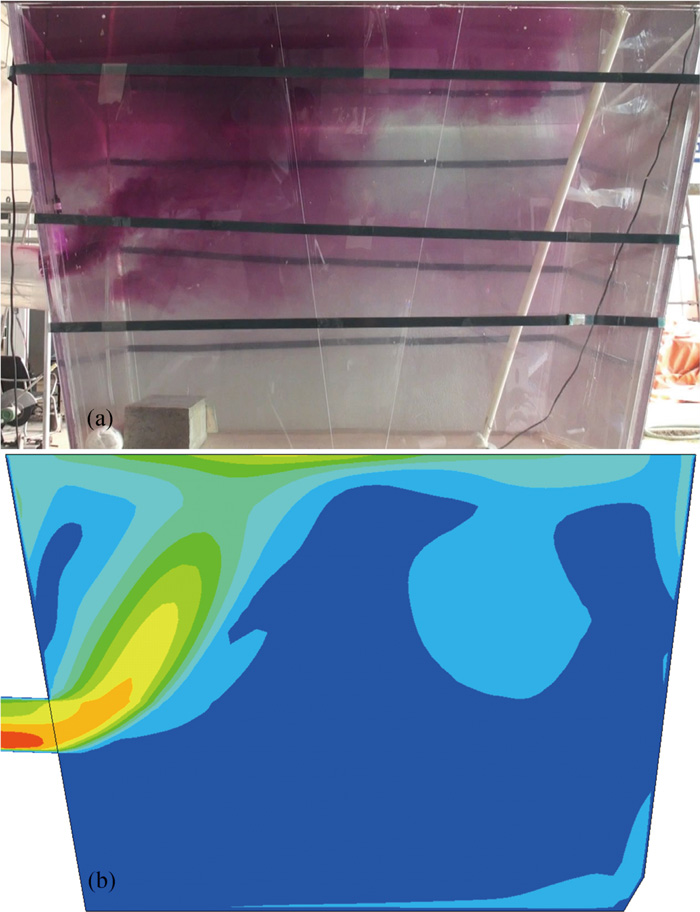
In order to validate the hydrodynamic model, a comparison of the flow field in the distributing chamber between Wang’s physical simulation40) and our numerical simulation was conducted (see Fig. 4). In the physical simulation, the dimension of the tundish was the same as ours, the flow rate was 200 kg/min, the initial water temperature was 20°C, hot water at 50°C with KMnO4 acted as the tracer was injected into the inlets of the channels to model the heating process. The same conditions were applied in the numerical simulation. It can be seen that the calculated and the experiment results are in good agreement.
3. Results and Discussion
The results are mainly revealed on some specific planes, for showing results in 3-D is too complicated to be understood clearly. Figure 5 displays the planes where we will show the results. Plane 1 lies in the section where the central axes of the two channels lie. Plane 2 is located on the centre vertical section of the left channel. Plane 3 and plane 4 are located on the centre cross section and the outlets of the channel, respectively.
3.1. Effective Active Zone of the Magnetic Field
It is essential to make an in-depth study about the electromagnetic field features of the induction heating tundish to understand the metallurgical process. Current literature studied this issue in general, however some interesting and important phenomena have not been thoroughly explored and discussed. In this section, the distribution of magnetic flux density and electromagnetic force is depicted in detail at the heating power of 800 kW.
The distribution of the magnetic field is shown in Fig. 6. Figure 6(a) shows the contour of the magnetic flux density on Plane 2, and the variation of the magnetic flux density along the central axis of the channel. Figure 6(b) shows the contour of the magnetic flux density on Plane 1, and the variation of the magnetic flux density along the radial direction of the channel. The contour indicates that the magnetic field mainly concentrates in the channels. In the two chambers, the magnetic flux density nearby the wall connected with the channels is significantly larger than that distributed in other zones. Previous studies7,9,11) mainly focused on the interior of the channels, and the magnetic field in the two chambers was ignored. In order to clarify the importance of the electromagnetic field in the chambers, the effective active zone of the magnetic field was obtained by analyzing dimensionless numbers: Ha, N and Re.

The Hartman number (Ha), representing the ratio of electromagnetic force to sheer force, is defined as:
The Interaction parameter (N), representing the ratio of electromagnetic force to inertia force, is defined as:
The Reynolds number (Re), representing the ratio of inertia force to sheer force, is defined as:
where
l is the characteristic length scale of the flow, equaling to the bath depth of 1 m. Besides,
u is the average velocity of the molten steel in the chambers, and it is equals to 0.3 m/s.
In this study, the value of Re in the chamber is about 3.5×10⁵, it means the inertia force is much larger than the sheer force. Therefore, only when the electromagnetic force is equivalent to the inertia force can the electromagnetic force have obvious effect on the flow of molten steel, that is to say, N is more suitable than Ha for evaluating the influence of the electromagnetic force on the flow.
Generally, when the value of N is smaller than 0.01, the influence of electromagnetic force can be neglected; whereas, when it reaches 1, the driving effect of electromagnetic force will be equivalent to that of the inertial forces, moreover, the electromagnetic force will significantly affect the flow of molten steel when it reaches the value of 0.1.
Bringing specific values of 0.01, 0.1 and 1 into formula (31), the critical values of electromagnetic flux density can be obtained, and they are equal to 0.0032 T, 0.0100 T and 0.0317 T, respectively. Therefore, as long as the electromagnetic flux density reaches 0.0100 T, the electromagnetic force will have significant effect on the molten steel. Figure 7 exposes the effective active zone of the electromagnetic field in the chambers. It can be seen that the magnetic field in the chambers near the walls connected with the channels can still affect the flow of the molten steel, though the magnetic flux density there is far smaller than that in the channels. In other words, the effective active zone of the electromagnetic field should contain the channels and the nearby walls connected with the channels.

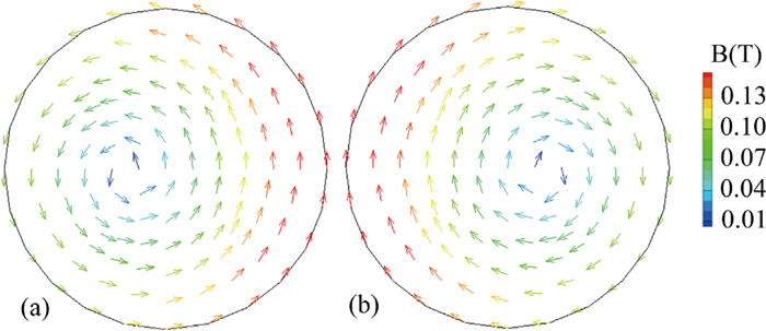
The magnetic flux density in the tundish is associated with the current in the coils and the induced current in the tundish. The variation of the magnetic flux density along the central axis of the channel (marked on Plane 2) was displayed in Fig. 6(a). It can be found that the magnetic flux density initially increases and then decreases from the inlet to the outlet of the channels along the central axis of the channel. The curve in Fig. 6(b) shows the variation of the magnetic flux density along the radial direction of the channel and the line for data extraction was also marked on Plane 1. It can be found that the magnetic flux density near the channel wall is lager compared with that located in the inner of the channel, besides, it is larger close to the coils. Figure 8 reveals that the magnetic flux density is rotational over the channel cross section. Besides, the superposition of the magnetic field causes the asymmetric distribution, as a result, the minimum value is not located in the center of the channels and its value is also not uniform along circular lines. This is consistent with the Vives’s observation.14)
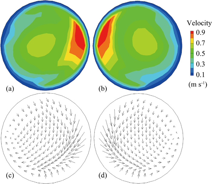
The electromagnetic force distribution is shown in Figs. 9 and 10. The electromagnetic force acting on the molten steel is generated by the interaction between the magnetic field and the induced current. Hence, the spatial distribution of the electromagnetic force is consistent with that of the magnetic field, and it points from the wall to the center of the channel, which forms a kind of “pinch effect”. The asymmetric pinch force will drive the molten steel to rotate dramatically. Besides, the non-metallic inclusions may be forced to move to the walls of the channels and removed from the molten steel, which is considered as an important advantage of the induction heating tundish. This issue will be investigated in subsequent work.


The component of electromagnetic force along the channel axis is non-existent in the channels, which is also observed in Vivies’s work. However, it rises significantly around the inlets and the outlets of the channels, owning to the deflection of the induced current line.14) As mentioned above, we found there are two effective active zones of the magnetic field in the two chambers. The four pictures in Fig. 11 sequentially show the electromagnetic force distribution within the four regions in Fig. 9. These pictures show several characteristics of the electromagnetic force: compared with the force near the joints of the channels and chambers, the force nearby the walls of chambers is smaller and points to the interior of the chambers, moreover, its direction is almost perpendicular to the Y-Z plane. Consequently, that will push molten steel away from the walls and accelerate it. The force around the throats of the channels is almost equivalent to that in the channels, and it also points from the mouth of the channels to the inside of the chambers, besides, there also exists weak pinch effect to some extent. This complicated situation will strongly change the flow pattern in the chambers. Lastly, it can be seen from Figs. 11(V1) and 11(V2) that the electromagnetic force next to the upper edge is larger than that close to the lower edge. This phenomenon can be illustrated by Fig. 12 clearly. Compared with the electromagnetic force distribution on the cross section of the channels (See Fig. 10), it is no longer symmetrical about the Z direction, and the force within the upper region is significantly larger. That will force the molten steel to flow downwards into the chambers when it rushes out from the outlets of the channels, and it may be a negative factor for removing inclusions. Consequently, this issue should be discussed in detail and the flow pattern strongly affected by the electromagnetic force will be exposed later.

The flow of the molten steel is the basic transport process in the induction heating tundish, so it is critical to analyse this phenomenon for understanding the energy transport and the movement of inclusions correctly. In a dual-channel type induction heating tundish, the flow in the distributing chamber is always the key for removing inclusions and obtaining uniform temperature field. To the best of our knowledge, there is no study about the influence of the asymmetrical distribution of the electromagnetic force around the throats of the channels on the flow in the distributing chamber. In order to resolve this issue and illustrate the effect of the electromagnetic force, the inertial force and the thermal buoyancy on the flow pattern in the distributing chamber, we calculated four cases with specific conditions, and they are listed in Table 4. The current frequency is 50 Hz in cases 2–4, and the duty ratios of the induction heater in cases 1–4 are 0%, 100%, 100% and 83%.
Table 4. Specific conditions for different cases.
| Cases | Conditions |
|---|
| 1 | Without induction heating (conventional tundish) |
| 2 | With joule heat of 800 kW + without electromagnetic force |
| 3 | With induction heating of 800 kW (with joule heat and electromagnetic force) |
| 4 | A situation that the induction heater is used intermittently |
Figure 13 shows the variation of the flow pattern in the distributing chamber of the tundish with different states. As shown in Fig. 13(a), under the condition of without the induction heating, the molten steel slowly rises to the free surface drived by the thermal buoyancy, that is due to the slight temperature difference between the molten steel in the channels and the distributing chamber (see Fig. 14(a)).
In case 2, the joule heat was applied to molten steel, however, the electromagnetic force was abandoned. Figure 13(b) shows that the molten steel rises to the free surface directly when it flows out of the channels. This is also driven by the thermal buoyancy. That is produced by the large temperature difference between the molten steel in the channels and the distributing chamber (see Fig. 14(b)).
With the consideration of the heating effect and the force effect of the induction heating, the molten steel does not timely ascend but appears a downward trend. Besides, once the main stream hits the inclined transverse wall, it will also ascend to the free surface along the wall (see Fig. 13(c)). There are two reasons that account for this phenomenon. One is that the velocity of the molten steel is accelerated when it passes through the channels; the other is that the electromagnetic force pointing downwards is larger than that pointing upwards near the channel outlet zones (shown in Fig. 12). The electromagnetic force with these distribution characteristics pushes the molten steel downwards at the channel outlets (see Fig. 15). According to the variation of the flow field in cases 1, 2 and 3, we draw the conclusions that the electromagnetic force around the channel throats can dramatically change the flow of molten steel in the distributing chamber, and the effective active zone of the magnetic field proposed in section 3.1 is reasonable; besides, the electromagnetic force and the inertial force together dominate the flow of the molten steel in an induction heating tundish, which means they have more effect on the flow of molten steel compared with thermal buoyancy.
During the casting process, an induction heater may be used intermittently to maintain the molten steel temperature. As mentioned above, when the induction heating is applied, the electromagnetic force controls the flow, and the thermal buoyancy has a significant effect on the flow when the induction heating is not applied. It should be noted that the working conditions may be bad when the induction heater is used intermittently during the period of power at 0 kW. We calculated this situation (case 4), and the flow pattern in the distributing chamber was depicted in Fig. 13(d). The temperature of the molten steel in the receiving chamber is lower than that in the distributing chamber and the molten steel is mainly heated in the channels when the induction heating is applied. However, when the induction heater is turned off, the molten steel with lower temperature will flow into the distributing chamber carrying higher temperature molten steel (see Fig. 14(d)). In this situation, the molten steel will flow directly to the bottom of the distribution chamber and can not ascend to the free surface along the transverse wall (see Fig. 13(d)), because there is no electromagnetic force to drive the molten steel to accelerate. That is a nightmare condition for the reason that the inclusions can not float up quickly.
3.4. The Behavior of the Inclusions in the Distributing Chamber
The movement of the inclusions in a tundish is always concerned by researchers and engineers because promoting the floating and removal of inclusions is an important task of the tundish. The electromagnetic force controls the flow of molten steel, and will affect the movement of inclusions indirectly. This section mainly illustrates the behavior of the inclusions in the distributing chamber with the flow fields described in section 3.3.
Figure 16 is the particle trajectories in the distributing chamber with different conditions. The trajectories of the inclusions are basically the same as the streamlines of molten steel shown in Fig. 13. When there is no electromagnetic force in the tundish, the values of inclusions velocity are basically the same (see Figs. 16(a), 16(b), 16(d)), and the only difference between them is the movement direction. When the molten steel is driven and accelerated by electromagnetic force, the inclusions are also carried and accelerated by the molten steel (see Fig. 16(c)). They are basically 3 times faster than that in the flow field being not influenced by electromagnetic force.

Figure 17 reveals the inclusions removal rate adsorbed by the tundish covering flux in the distribution chamber with different flow field. It can be found that in the same flow field when the molten steel is not accelerated by electromagnetic force, the larger the inclusions are, the higher the removal rate is. However, when the molten steel is accelerated by electromagnetic force, the removal rate of inclusions may be independent of the particle size. When the particle size is the same, the inclusions removal rate of case 2 is the highest, case 3 is the second, case 1 is the third and case 4 is the lowest. Moreover, the differences between the cases 1 and 3, cases 4 and 3 decrease with the increase of the particle size of the inclusions. That means the electromagnetic force plays a key role in removing the small inclusions in a channel type induction heating tundish.

Inclusions in the tundish have three destinies: floating up and being removed, suspended in molten steel and flowing into the mold. It is expected that as few inclusions as possible enter the mold from the tundish. In order to reveal the influence of the flow field on the inclusions flowing out of the tundish, as shown in Fig. 18, we calculated the proportion of inclusions with different particle sizes entering the mold in different flow fields. It is clear that the proportion of inclusions entering the mold (defined as the escaping ratio) is the highest for case 4, and a maximum of the inclusions (more than 70%) enters the mold. In other cases, the highest escaping ratio reaches 40% when the induction heating is not applied. The escaping ratio is about 30% with the induction heating being applied, and it seems to be independent of particle size. Though situation 2 gives the lowest escaping ratio, it is ideal.

The removal ratio of the inclusions is a significant index to evaluate the pros and cons of the flow field, besides, the floating up and removal speed of the inclusions is another essential criterion. In this study, all the inclusions removed by floating were classified every 60 s according to the removal time, and the percentage of all the inclusions removed in each group was calculated. Figure 19 displays the results in different cases. We found that the inclusions, regardless of their size, were mainly (more than 70%) removed within 60 s in case 2 and 3, besides, almost all the inclusions were removed within 300 s in case 3. That is an exciting phenomenon. However, the inclusions could not be removed within 60 s in case 4, and they were mainly removed after 180 s. These results can be explained by Fig. 16. The movement distance of the inclusions in case 2 is the shortest, and the particle velocity is the highest in case 3, so the inclusions will rise most rapidly in these two cases. In case 4, the molten steel can not ascend to the free surface quickly, so the inclusions will also stay in the bottom of the chamber with the molten steel at lower temperature for a long time.

4. Conclusions
The electromagnetic characteristics of a dual-channel type induction heating tundish were simulated by using finite element method, and the transport process including flow, heat transfer and the movement of inclusions in the tundish was explored using the finite volume method. This work mainly discloses the influence of the asymmetrical distribution of the electromagnetic force on the flow and the movement of the inclusions in the distributing chamber of a dual-channel type induction heating tundish being used for single-strand slab casting. It lays a foundation for optimizing tundish structure and casting process in future. The main conclusions are summarized as follows:
(1) We obtained the effective active zone of the magnetic field by analysing the dimensionless parameters Ha, N and Re. It mainly contains the channels and the zones nearby the walls connected with the channels. Although the magnetic flux density distributed in the chambers is smaller than that in the channels, it has a significant effect on the flow of the molten steel and should not be ignored.
(2) The electromagnetic force distributed in the chambers points from the wall to the interior, and its asymmetrical distribution around the channel outlets is notable. It is larger within the upper zones of the channel outlets. As a result, it inhibits the ascent of the main stream in the distributing chamber. Both the electromagnetic force and the inertial force dominate the flow of the molten steel in the induction heating tundish, and they have a greater effect on the flow of molten steel compared with thermal buoyancy. Only when the induction heating is turned off and the velocity of the molten steel entering the distributing chamber is small, can the thermal buoyancy control the flow of the molten steel.
(3) The small inclusions with a diameter less than 80 μm are primarily carried by the molten steel to move, so their trajectories is basically consistent with the main stream of molten steel. It is essential to promote the molten steel to rise to the free surface rapidly to remove the inclusions quickly and efficiently. When the induction heating is applied, about 75% of the inclusions entering the distribution chamber, regardless of the particle size, will be adsorbed by the tundish covering flux. Besides, about 70% and 90% of the adsorbed inclusions will float to the free surface within 60 s and 120 s, respectively. The electromagnetic force plays a key role in removing the small inclusions (diameter less than 60 μm) in a channel type induction heating tundish.
(4) During the casting process, the induction heater should not be used intermittently, because 40%–80% of the inclusions may enter the mold directly during the period of power at 0 kW.
Acknowledgements
This work was supported by National Natural Science Foundation of China (51474065, 51574083) and the 111 Project (2.0) of China (No. BP0719037).
References
- 1) Y. Sahai: Metall. Mater. Trans. B, 47 (2016), 2095.
- 2) B. Fredrikson, S. Hellsing and K. Folgero: Channel-type Induction Furnace, U.S. Patent 3618917, (1971).
- 3) P. Marty and A. Alemany: Metallurgical Applications of Magnetohydrodynamics, Proc. Symp. Int. Union of Theoretical and Applied Mechanics, Metals Society, London, (1984), 245.
- 4) Y. Yoshii, Y. Habu, H. Yamanaka and T. Ueda: Method of Heating a Molten Steel in a Tundish for a Continuous Casting Apparatus, U.S. Patent 4582531, (1986).
- 5) B. G. Thomas: Steel Res. Int., 89 (2018), 1700312.
- 6) B. G. Thomas: Voest Alpine Conf. on Continuous Casting, (Linz), Continuous Casting Consortium, Urbana, (2000), 1.
- 7) J. I. Ghojel: Prog. Comput. Fluid Dyn., 6 (2006), 435.
- 8) T. Zhao, J. M. Zhou, J. Z. Xiong and Y. Li: J. Cent. South Univ. Technol., 16 (2009), 851.
- 9) A. A. Alferenok and A. B. Kuvaldin: Russ. Metall. (Metally), 2009 (2009), 741.
- 10) J. I. Ghojel and R. N. Ibrahim: J. Mater. Process. Technol., 153–154 (2004), 386.
- 11) Q. Wang, B. K. Li and F. Tsukihashi: ISIJ Int., 54 (2014), 311. https://doi.org/10.2355/isijinternational.54.311
- 12) B. Yang, H. Lei, Q. Bi, J. Jiang, H. W. Zhang, Y. Zhao and J. A. Zhou: Steel Res. Int., 89 (2018), 1800145.
- 13) B. Yang, H. Lei, Q. Bi, J. Jiang, H. W. Zhang, Y. Zhao and J. A. Zhou: Steel Res. Int., 89 (2018), 1800173.
- 14) C. Vives and R. Ricou: Metall. Trans. B, 22 (1991), 193.
- 15) E. Baake, A. Jakovics, S. Pavlovs and M. Kirpo: COMPEL-Int. J. Comput. Math. Electr. Electron. Eng., 30 (2011), 1637.
- 16) M. Kirpo, A. Jakovičs, B. Nacke, E. Baake and M. Langejürgen: Prz. Elektrotech., 84 (2008), 154.
- 17) A. Moros and J. C. R. Hunt: Int. J. Heat Mass Transf., 31 (1988), 1497.
- 18) Q. Yue, C. B. Zhang and X. H. Pei: Ironmaking Steelmaking, 44 (2017), 227.
- 19) H. Y. Tang, X. S. Li, S. Zhang and J. Q. Zhang: Acta Metall. Sin., 56 (2020), 1629.
- 20) S. Joo, J. W. Han and R. I. L. Guthrie: Metall. Trans. B, 24 (1993), 767.
- 21) S. Chakraborty and Y. Sahai: ISIJ Int., 31 (1991), 960. https://doi.org/10.2355/isijinternational.31.960
- 22) D. Y. Sheng and L. Jonsson: Metall. Mater. Trans. B, 31 (2000), 867.
- 23) W. Yamada, A. Kiyose, J. Fukuda, H. Tanaka and J. I. Nakashima: Ironmaking Steelmaking, 30 (2003), 151.
- 24) G. Solorio-Díaz, R. D. Morales and A. Ramos-Banderas: Int. J. Heat Mass Transf., 48 (2005), 3574.
- 25) F. Xing, S. G. Zheng and M. Y. Zhu: Steel Res. Int., 89 (2018), 1700542.
- 26) S. Pavlovs, A. Jakovics, E. Baake and B. Nacke: Proc. 8th Int. Conf. on Clean Steel, (Budapest), OMBKE, Budapest, (2012).
- 27) F. Xing, S. G. Zheng, Z. H. Liu and M. Y. Zhu: Metals, 9 (2019), 561.
- 28) Q. Wang, F. S. Qi, B. K. Li and F. Tsukihashi: ISIJ Int., 54 (2014), 2796. https://doi.org/10.2355/isijinternational.54.2796
- 29) S. Taniguchi and J. K. Brimacombe: ISIJ Int., 34 (1994), 722. https://doi.org/10.2355/isijinternational.34.722
- 30) H. Lei, B. Yang, Q. Bi, Y. Y. Xiao, S. F. Chen and C. Y. Ding: ISIJ Int., 59 (2019), 1811. https://doi.org/10.2355/isijinternational.ISIJINT-2019-118
- 31) Q. Zhang, G. Y. Xu and K. Iwai: ISIJ Int., 61 (2021), 42. https://doi.org/10.2355/isijinternational.ISIJINT-2020-306
- 32) K. Sassa and S. Asai: CAMP-ISIJ, 12 (1999), 6.
- 33) Y. Li, A. Y. Deng, H. Li, B. Yang and E. G. Wang: Metals, 8 (2018), 76.
- 34) F. Felten, Y. Fautrelle, Y. Du Terrail and O. Metais: Appl. Math. Model., 28 (2004), 15.
- 35) B. E. Launder and D. B. Spalding: Comput. Methods Appl. Mech. Eng., 3 (1974), 269.
- 36) K. Hanjalić and S. Kenjereš: Flow Turbul. Combust., 66 (2001), 427.
- 37) A. Tripathi and S. K. Ajmani: ISIJ Int., 51 (2011), 1647. https://doi.org/10.2355/isijinternational.51.1647
- 38) H. T. Ling, R. Xu, H. J. Wang, L. Z. Chang and S. T. Qiu: ISIJ Int., 60 (2020), 499. https://doi.org/10.2355/isijinternational.ISIJINT-2019-506
- 39) G. C. Wang, M. F. Yun, C. M. Zhang and G. D. Xiao: ISIJ Int., 55 (2015), 984. https://doi.org/10.2355/isijinternational.55.984
- 40) C. S. Wang: M.D. thesis, University of Science and Technology Liaoning, (2015), 37, https://cdmd.cnki.com.cn/Article/CDMD-10146-1016144339.htm, (accessed 2021-01-19).