Abstract
Contact-type flatness meters are the key detection equipment in the production of high-end cold-rolled thin strips. The surface performance of a flatness meter roller is very important to improve its service life and ensure the surface quality of strip products. To improve the surface wear resistance and prolong the service life of a seamless flatness meter roller, it was subjected to a surface strengthening treatment by laser cladding an Fe-based wear-resistant alloy. The performance of the flatness meter roller strengthened by laser cladding and quenching was determined by tests. The results show that the laser cladding-strengthened layer forms a solid metallurgical bond with the roller matrix. When the laser cladding-strengthened surface meets the surface strength, hardness and thickness requirements of the cladding-strengthened layer, the average width of wear marks in the 30-minute sliding friction wear test is only 1.43 mm. The wear resistance of the cladding-strengthened layer is approximately 24% higher than that of the quenching-strengthened layer. This paper proposes a new approach for the research and development of the surface strengthening technology of cold-rolled strip seamless flatness meter rollers.
1. Introduction
In recent years, with the rapid development of the global steel industry, users’ demand for high-quality cold-rolled strips has increased rapidly,1,2,3,4) and the strip quality requirements are continually increasing, especially for the surface quality of high-quality strips. Flatness is an important quality index of cold-rolled strips. Flatness detection and control are the key technologies for producing high-quality cold-rolled strips. A flatness meter is the key equipment of a contact flatness detection system, among which the seamless flatness meter detection roller5,6,7,8,9,10) (hereafter referred to as the detection roller) is the only integrated flatness meter roller thus far. The roller surface is a complete and seamless cylindrical surface, which avoids crushing and scratching the strip surface. Compared with the fragment-type (ABB Stressometer), cylinder sensor-type (early BFI flatness meter) and sensor embedded-type (made early in China) detection rollers, the seamless type is also easier to maintain, which makes it the future development trend of detection rollers. It is suitable for temper mill strips, finishing mill strips, galvanized strips, nonferrous metal strips and other products with strict surface requirements.
The special feature of the detection roller structure is that a large number of precision pressure sensors are arranged in the mounting holes under the complete roller surface. The pressure sensor and the mounting hole are joined by an interference fit, so the roller surface needs to have high strength to prevent the roller surface from cracking by force. At the same time, the detection roller is precision detection equipment that costs millions of dollars, and most manufacturers do not have a backup roller. To ensure the long-term stable online operation of detection rollers, their surfaces must have higher hardness and wear resistance. Therefore, material selection and surface treatment technology are especially important when designing detection rollers. At present, quenching is often used to strengthen the performance of a roller surface, which results in a strengthened layer with limited depth. In the production process, the roller surface experiences wear under some bad working conditions, such as speed mismatch or misoperation, as shown in Fig. 1. The wear defects on the surface of a detection roller seriously affect the surface quality of the strip products and are often repaired by a grinding roller, resulting in the thinning of the strengthened layer on the surface and decreasing the service life of the detection roller. Therefore, the strengthening technology of flatness meter detection roller surfaces and methods to improve the quality of roller surfaces, especially their wear resistance, are important research topics.

Laser cladding surface strengthening is an important laser additive manufacturing method.11,12) It is a metal surface-strengthening method with a wider range of applications than thermal spraying and electroplating technologies. It solves many problems in the strengthening process, such as thermal stress, thermal deformation and the difficulty in guaranteeing material bonding strength, that cannot be solved by other traditional methods. Laser cladding is often used in the surface repair and surface modification of basic materials and can not only obtain specific performance but also save many expensive resources. Many studies have performed laser cladding to improve the surface properties, especially the wear resistance, of steel. X. P. Tao et al.13) used laser cladding to prepare an aluminum bronze coating containing iron and nickel on the surface of 316L stainless steel and found that the wear resistance was the best when the hardness of the coating was increased to 244 ± 12 HV0.3. Zhaoliang Li et al.14) prepared an Al2O3–TiB2–TiC ceramic coating with high hardness and wear resistance on the surface of carbon steel by changing the alloy powder composition. Large black Al2O3, white granular TiB2 and TiC were all distributed on the Fe matrix. The stability, microhardness and wear resistance of Fe were significantly improved. Z. K. Fu et al.15) studied the wear of rail material and analyzed the hardness and wear resistance of rail surfaces strengthened by laser cladding. The results showed that the Fe-based alloy coating prepared by laser cladding was composed of dendrites and eutectic materials. The hardness and wear resistance of the wheel and rail were enhanced by laser cladding technology. Li Meng et al.16) studied the wear resistance and fatigue strength of nickel-based alloys prepared on rail surfaces by laser cladding, and the results showed that nickel-based alloy coatings prepared by laser cladding have a significant impact on improving the damage characteristics of rail rollers. K. W. Ng et al.17) improved the wear resistance of a copper matrix by preparing a molybdenum and nickel coating on the surface of an electrical joint by laser cladding, overcoming the difficulties of the differences in thermal properties and low mutual solubility, and the wear resistance obtained was 7 times higher than the original value, thus prolonging the service life. Yiqiang Wang et al.18) applied HT300 on the guide roller surface by laser cladding, which improved the rolling wear resistance of the linear rolling guide of the machine tool and extended its service life. In the production process of steel rolling products, to improve the wear resistance and strength of hot rolls, X. Li et al.19) prepared a self-lubricating coating composed of a metal matrix composite material on the surface of 35CrMo steel by laser cladding. The coating improved the wear resistance of the matrix material by approximately 84% within the range of 507±11 HV–595±12 HV. W. Kaiming et al.20) applied NiCrBSi/Mo alloy powder on the surface of a 42CrMo roll by laser cladding. The microhardness of the cladding layer was significantly higher than that of the matrix, and the wear resistance was significantly improved.
As high-end precision equipment, there is little research on the surface strengthening of flatness meter detection rollers. In this paper, laser cladding of an Fe-based wear resistant alloy onto the surface of a detection roller is carried out, and the performance of the resulting material is compared with that of a material prepared by surface quenching, especially the wear resistance, to study the feasibility and superiority of preparing coatings on the surface of detection rollers by laser cladding, which provides a new idea and new direction for the study of the surface hardening technology of detection rollers.
2. Laser Cladding and Surface Performance Test
2.1. Laser Cladding Test
2.1.1. Principle of Laser Cladding
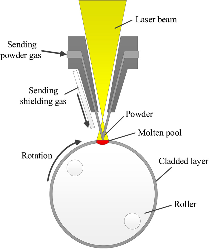
Laser cladding refers to the simultaneous melting and rapid solidification of the cladding alloy powder and the thin layer of the matrix material by laser irradiation so that the matrix and the cladding alloy form a metallurgical combination to obtain the excellent properties of the cladding alloy, as shown in Fig. 2. The laser cladding process is the metallurgical process of the interaction between a laser and alloy powder, the laser and matrix material and alloy powder and matrix material.
2.1.2. Powder Selection, Cladding Method and Process Parameters
In industrial applications, Fe-based 401 fluxed alloy powder is often used in the laser cladding of workpiece surfaces. It can replace industrial chromium plating to some extent. The cladding surface has the advantages of high hardness and high wear resistance, similar to the Cr layer, and has a better effect due to its combination and thickness than the Cr layer. This paper uses Fe-based 401 alloy powder as the cladding material. Its elemental content is shown in Table 1. Due to the poor bonding ability between the GCr15 matrix and the Fe-based wear-resistant alloy, cracks easily occur. Therefore, a transition layer should be added between the cladding-strengthened layer and the matrix. The hardness of the transition layer is lower than that of the strengthened layer and slightly higher than that of the matrix of the detection roller, which forms a good gradient coating and reduces the possibility of cracking in the strengthened layer to realize laser cladding and strengthen the roller surface. In this paper, 316L stainless steel powder is selected as the transition layer powder. It is often used as a transition layer material in industrial applications. Many industrial tests have verified that 316L stainless steel powder can achieve a good combination between the strengthening layer and the matrix. Its elemental content is shown in Table 2. The strengthening test is performed on the laser clad surface of the detection roller by adopting a synchronous powder feeding method, and the laser is a semiconductor laser. The main technological parameters are as follows: effective cladding power of 1500 W, scanning speed of 200 mm/min, spot diameter of 5 mm, and lap rate of 50%.
Table 1. Main elements of 401 Fe-based wear-resistant alloy powder.
| Element | Fe | Cr | Mo | Ni | C | Others |
|---|
| Content/% | Rest | 18 | 0.5 | 2.5 | 0.15 | <7 |
Table 2. Main elements of 316L stainless steel alloy powder.
| Element | Fe | Cr | Mo | Ni | Si | Mn |
|---|
| Content/% | Rest | 17 | 2.5 | 12 | 0.8 | 1.5 |
First, Φ 313 mm×300 mm experimental detection rollers were made. Then, laser cladding was carried out to strengthen the roller surface, including two stages, preheating and cladding with feeding. Finally, after grinding the strengthened roller, the sensors were installed, and the roller surface was inspected for observation to ensure that there was no crack. Figure 3 shows a detection roller undergoing laser cladding.
2.2. Methods for Testing Surface Cladding Performance
2.2.1. Roller Surface Strength Test
The sensor installation test can be performed to determine whether the strength of the roller surface after laser cladding meets the requirements. After the pretightening force was applied, the roll surface was 0.03 mm larger than the original size. Then, the conditions met the service requirements, so the roller surface did not crack, which means that the surface strength met the requirements.
2.2.2. Surface Hardness and Hardness Change of the Hardening Layer Test
The engineering application shows that the hardness of the detection roller surface should be greater than 590 HV (55 HRC) and that the thickness of the effective strengthening layer should be greater than 1 mm. Three hardness samples were taken from each of the two rollers and subjected to two strengthening methods, and the microhardness test was conducted. The hardness was measured every 0.25 mm along the radial direction from the surface of the roller to obtain the hardness change of the hardening layer.
2.2.3. Metallography and Scanning Electron Microscope (SEM) Energy Spectrum
The metallographic sample prepared with laser cladding and metallographic sample prepared with quenching were taken. The etchant of the cladded sample was an aqueous ferric chloride solution acid, and the etchant of the quenched sample was 4% nitric alcohol. Corrosion was observed under a light microscope. Multipoint line scanning was performed with an SEM-energy dispersive spectroscopy system to detect the position, thickness, strengthening layer elemental distribution and diffusion mode according to a preset straight line. The quenched sample did not show the diffusion of metal elements, so only the cladding-strengthened sample required radial line scanning.
2.2.4. Friction and Wear Test
An MMS-2A friction and wear testing machine, shown in Fig. 4, was used to carry out ring block friction and wear tests at room temperature. The friction coefficient, load and friction moment of the specimen were recorded in real time during the movement process. Four groups of friction tests were carried out for both strengthening methods. The test parameters are shown in Table 3.
Table 3. Scheme of the friction and wear test.
| Load/N | Rotation speed/r·min−1 | Period/min | Grinding ring material | Grinding ring hardness | Grinding ring diameter/mm | Temperature/°C | Lubrication |
|---|
| 200 | 100 | 30 | GCr15 | 50 HRC | 40 | room temperature | 0.02 ml glycerin |
The friction coefficient, wear morphology and wear quantity are important parameters used to characterize the friction properties of materials.21,22,23) The friction coefficient is the ratio of the friction moment between two contact surfaces to the positive pressure perpendicular to the surface and the radius of the grinding ring. The test results are directly derived from the wear testing machine. The wear morphology is an important basis to judge the wear mode, and it can be determined using a microscope. The wear quantity includes the mass wear quantity and volume wear quantity. The mass wear quantity can be measured by a high-precision balance, the volume wear quantity can be measured by the wear mark width and calculated by Formula 1, and the volume wear rate can be calculated by Formula 2.
|
V=(
1
2
r
2
arccos
2
r
2
-
w
2
2
r
2
-
1
2
w
r
2
-
w
2
4
)
b
| (1) |
where
V is the wear volume;
w is the width of the sample wear mark;
r is the radius of the grinding ring, which is 20 mm; and
b is the length of the sample (7 mm). The volume wear rate
K is as follows:
where
F is the applied load (N) and
T is the sliding stroke (m).
3. Analysis and Comparison of Test Results
3.1. Sensor Installation
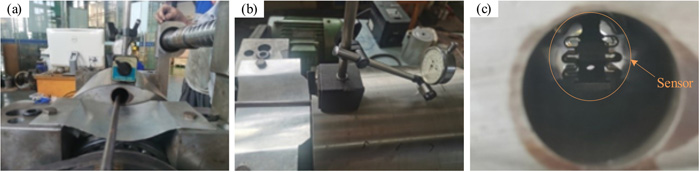
After performing quenching and laser cladding to strengthen the surface of the detection roller, the sensor is installed, as shown in Fig. 5. When applying a pretightening force, a steel pad with a precise size should be inserted into the sensor block, as shown in Fig. 5(a). A dial indicator is used to measure the displacement of the roller surface. When the indicated number changes by more than 0.03 mm, the preload is applied, as shown in Fig. 5(b). The detection roller is observed, and whether the roller surface has cracks is determined. The sensor is installed, and the preload is successfully applied when the above steps are completed, as shown in Fig. 5(c). At this point, if the roller surface does not exhibit defects, the sensor is installed, quenching and laser cladding are performed to strengthen the roller, and the roller surface strength meets the requirements.
3.2. Comparison between Surface Hardness and Hardening Layer Hardness
3.2.1. Surface Hardness
The surface microhardness test results of the two strengthening methods are shown in Table 4. The lowest hardness value of the clad surface is 686 HV, and the average value is 697.2 HV. The lowest hardness value of the quenched surface is 710 HV, and the average value is 721 HV. The hardness of the roller surface strengthened by laser cladding is slightly lower than that of the quenched roller surface, but the difference is not significant; the hardnesses are both greater than 590 HV, which meets the surface hardness requirements of the detection roller.
Table 4. Comparison of roller surface hardness results (HV).
| Sample | 1 | 2 | 3 | 4 | 5 | Average value |
|---|
| Laser cladding | 686 | 694 | 704 | 698 | 704 | 697.2 |
| Quenching | 729 | 723 | 719 | 724 | 710 | 721 |
As shown in Fig. 6(a), the roller surface subjected to laser cladding can be divided into three parts from the strengthened layer to the matrix. The first part is the laser clad strengthened layer with a thickness greater than 1 mm. The thickness and hardness of the effective clad layer meet the requirements of the surface of the detection roller. The second part is the middle transition layer, which is mostly 316L stainless steel. The third part is the matrix. The quenched roller surface can also be divided into three parts from the strengthened layer to the matrix. The first part is the effective strengthened layer, whose hardness is more than 590 HV and thickness is more than 1 mm. The second part is an ineffective strengthened layer; although it is affected by quenching, its hardness is low. The third part is the matrix, whose hardness does not change obviously. The surface of the quenched roller can also be divided into three layers according to the hardness changes: the effective strengthened layer, ineffective strengthened layer and matrix. The thickness of the effective strengthened layer is more than 1.25 mm.
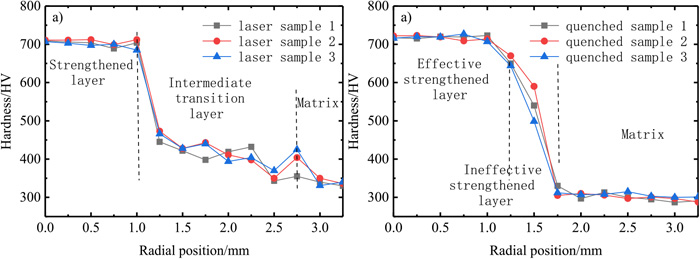
Figure 7 shows the metallographic structure of cladding-strengthened and quenching-strengthened roller surfaces. Figure 7(a) shows the bonding surface topography after strengthening by cladding. The upper layer is the laser cladding-strengthened layer, the middle transition layer is the stainless steel alloy layer, and the lower layer is the matrix. By magnifying the bonding surface between layers, as shown in Figs. 7(b) and 7(c), bonding between layers can be clearly seen. Figure 7(d) shows the metallographic structure of the strengthened layer of the Fe-based wear-resisting alloy, which is a columnar dendrite structure with directional growth, a compact distribution and fine grains. Figure 7(e) shows that the color of the quenching-strengthened layer is different from that of the matrix, and the carbide segregation zone can be clearly seen at the junction of the two layers. The lower GCr15 matrix-bearing steel has fine grains and a pearlite structure with carbide particles distributed uniformly. Figure 7(f) is the quenched surface layer of the upper layers. The main structure is martensite with small grains accompanied by a large number of carbide particles.

Figure 8 shows the change in the contents of Cr, Fe, Mo, Ni and other major elements in the roller body treated with cladding. The horizontal coordinate from left to right corresponds to the radial direction of the roller body from inside to outside. Different intervals correspond to the three parts of the matrix material, the middle transition layer and the cladding-strengthened layer. The contents of Cr, Mo and Ni increase at a radial coordinate of approximately 270 μm, while the content of Fe decreases up to approximately 360 μm and remains stable. At approximately 1500 μm, the contents of Fe and Cr slowly increase, while the contents of Mo and Ni slowly decrease up to approximately 1580 μm and remain stable. The change in elemental content at the two sites can be attributed to the formation of compounds different from those in the strengthening layer, middle layer and matrix. The elements diffuse between layers, and the thickness of the diffusion layer is more than 80 μm, forming a solid metallurgical bond.

Figures 9 (a) to 9(d) show the friction coefficients of the laser clad samples. In the severe sliding friction and wear test, the wear of materials is aggravated, and the friction coefficients fluctuate greatly. The friction coefficients in the later stage are stable at approximately 0.2. Figures 9(e) to 9(f) show the friction coefficient of the quenched sample. The friction coefficient of the quenched sample is also stable at approximately 0.2. The mean values of the friction coefficients of the four tests are 0.242, 0.239, 0.231 and 0.247. Under the same friction test conditions, the friction coefficient curves of the laser cladding-strengthened and quenched roller samples are similar.
3.5.2. Comparison of Wear Morphology
Figures 10(a) to 10(d) show the wear morphology of the laser clad samples. By comparing the wear morphologies of the four groups of tests, there are furrows of different depths in the surface layer of the materials, and the wear mode is mainly abrasive wear. Figure 10(b) shows that the furrows are deep and that the surface layer is pitted due to wear. The wear degree of the other three laser clad samples is relatively low. Figures 10(e) to 10(h) show the wear morphology of the quenched sample, which can be seen clearly from the table. The quenched specimen shows serious wear. Figures 10(h) and 10(e) show that the surface has a large area of material loss, serious adhesive wear, and large furrows. Figure 10(f) shows that the furrows are deep and dense. Compared the wear morphologies shows the surface of the cladding-strengthened sample is obviously better than that of the quenched sample, although there is material shedding on the surface.
3.5.3. Ratio of Wear
The test results, including the wear mark width, wear volume and volume wear rate, are shown in Table 5. The maximum wear width of the cladded layer is 1.4620 mm, the average wear width is 1.4447 mm, the minimum wear width of the quenched layer is 1.5683 mm, and the average wear width is 1.5841 mm. Under the experimental conditions of 200 N and 100 r/min, the wear width, wear volume and volume wear rate of the cladding-strengthened roller surface are smaller than those of the quenching-strengthened roller surface. The results show that the wear resistance of the roller surface strengthened by laser cladding is better than that of the roller surface strengthened quenching. According to the wear rate, the wear resistance of the roller surface strengthened by laser cladding is approximately 24% higher than that of the roller surface strengthened by quenching under the existing test conditions.
Table 5. Comparison of wear width, wear depth and wear rate results.
| Test condition | 1 | 2 | 3 | 4 | Average value |
|---|
| Wear width/mm | Cladded layer | 1.4308 | 1.4620 | 1.4348 | 1.4513 | 1.4447 |
| Quenched layer | 1.5984 | 1.5683 | 1.5812 | 1.5885 | 1.5841 |
| Wear volume/mm3 | Cladded layer | 0.0855 | 0.0912 | 0.0862 | 0.0892 | 0.0880 |
| Quenched layer | 0.1192 | 0.1126 | 0.1154 | 0.1170 | 0.1160 |
| Wear rate/10–6 mm3·(N·m)−1 | Cladded layer | 1.13 | 1.21 | 1.14 | 1.18 | 1.17 |
| Quenched layer | 1.58 | 1.49 | 1.53 | 1.55 | 1.54 |
4. Conclusion
(1) Laser cladding of Fe-based wear-resistant alloy on a detection roller with the addition of a 316L stainless steel middle transition layer can prevent cracks from forming on the roller surface. The diffusion layer is more than 80 μm thick, and the bonding mode between layers is metallurgical bonding.
(2) The strength of the laser cladding-strengthened iron-based alloy layer meets the requirements of use. The average hardness of the cladding-strengthened layer reaches 697.2 HV, and the effective thickness of the cladded layer is more than 1 mm, which meets the strength, hardness and thickness requirements of the detection roller strengthening layer.
(3) Under the same friction and wear test conditions, there is little difference between the friction coefficients resulting from laser cladding and quenching. The wear morphology comparison shows that the wear of the strengthened layer is more severe than that of the cladded layer. According to the definition of wear rate, the wear resistance of the detection roller strengthened by laser cladding is 24% higher than that strengthened by quenching, making laser cladding a superior strengthening method.
References
- 1) S. Li, Y. Yin, J. Xu, J. Hou and J. Yoon: J. Iron Steel Res. Int., 14 (2007), 8. https://doi.org/10.1016/S1006-706X(07)60082-X
- 2) C. Klinkenberg, B. Kintscher, K. Hoen and M. Reifferscheid: Steel Res. Int., 88 (2017), 1700272. https://doi.org/10.1002/srin.201700272
- 3) X. Kou, S. Liu, K. Cheng and Y. Qian: Measurement, 182 (2021), 109454. https://doi.org/10.1016/j.measurement.2021.109454
- 4) Y. Xu, D. Wang, B. Duan, H. Yu and H. Liu: Appl. Sci., 11 (2021), 8945. https://doi.org/10.3390/app11198945
- 5) H. Liu, J. Liu, B. Yu, L. Yang and Y. Zhang: J. Mech. Eng., 53 (2017), 87 (in Chinese).
- 6) D. Wang, H. Liu and J. Liu: Chin. J. Mech. Eng., 30 (2017), 1248.
- 7) H. Yu, H. Liu, Y. Xu and D. Wang: Iron Steel, 54 (2019), 52 (in Chinese).
- 8) D. Wang, H. Liu and J. Liu: Chin. J. Mech. Eng., 30 (2017), 1248.
- 9) H. Yu, T. Zhang, S. Zhang, D. Wang and H. Liu: ISIJ Int., 61 (2021), 2571. https://doi.org/10.2355/isijinternational.ISIJINT-2021-006
- 10) H. Yu, D. Wang, H. Liu, T. Zhang and L. Yang: ISIJ Int., 60 (2020), 939. https://doi.org/10.2355/isijinternational.ISIJINT-2019-472
- 11) W. Yuan, R. Li, Z. Chen, J. Gu and Y. Tian: Surf. Coat. Technol., 405 (2021), 126582. https://doi.org/10.1016/j.surfcoat.2020.126582
- 12) J. Zhang, S. Shi, Y. Gong, S. Yu, T. Shi and G. Fu: Surf. Technol., 49 (2020), 1 (in Chinese).
- 13) X. Tao, S. Zhang, C. Zhang, C. Wu, J. Chen and A. Abdullah: Surf. Coat. Technol., 342 (2018), 76. https://doi.org/10.1016/j.surfcoat.2018.02.032
- 14) Z. Li, M. Wei, K. Xiao, Z. Bai, W. Xue, C. Dong, D. Wei and X. Li: Ceram. Int., 45 (2019), 115. https://doi.org/10.1016/j.ceramint.2018.09.140
- 15) Z. Fu, H. Ding, W. Wang, Q. Liu, J. Guo and M. Zhu: Wear, 330–331 (2015), 592. https://doi.org/10.1016/j.wear.2015.02.053
- 16) L. Meng, B. Zhu, C. Xian, X. Zeng, Q. Hu and D. Wang: Wear, 458–459 (2020), 203421. https://doi.org/10.1016/j.wear.2020.203421
- 17) K. W. Ng, H. Man, F. Cheng and T. Yue: Appl. Surf. Sci., 253 (2007), 6236. https://doi.org/10.1016/j.apsusc.2007.01.086
- 18) Y. Wang, B. Liu and Z. Guo: Opt. Laser Technol., 91 (2017), 55. https://doi.org/10.1016/j.optlastec.2016.12.015
- 19) X. Li, C. Zhang, S. Zhang, C. Wu, Y. Liu, J. Zhang and M. Babar Shahzad: Opt. Laser Technol., 114 (2019), 209. https://doi.org/10.1016/j.optlastec.2019.02.001
- 20) K. Wang, Y. Li, H. Fu, Y. Lei, Z. Su and P. Ma: Surf. Eng., 34 (2018), 267. https://doi.org/10.1080/02670844.2016.1259096
- 21) B. Zhang, H. Wang, R. Chen, B. He, Y. Cao and D. Liu: Surf. Eng., 37 (2021), 669. https://doi.org/10.1080/02670844.2020.1840758
- 22) W. Zhuang, Q. Liu, R. Djugum, P. K. Sharp and A. Paradowska: Appl. Surf. Sci., 320 (2014), 558. https://doi.org/10.1016/j.apsusc.2014.09.139
- 23) B. Xu and S. Zhu: Theory and Technology of Surface Engineering, National Defense Industry Press, Beijing, (2010), 429.