Regular Article
Effect of Process Parameters on Mineralisation Consolidation in Carbon-free Iron Ore Sintering Process

2023 年 63 巻 10 号 p. 1587-1594
詳細
2023 年 63 巻 10 号 p. 1587-1594
Sintering, as one of the major sources of carbon emissions in the steel industry, is in urgent need of innovation in carbon reduction technology under the targets of carbon peaking and carbon neutrality in China. We propose the carbon free sintering process which is similar to the belt roaster, where heat is provided by gas fuel combustion for the layer. In order to achieve the process, this study uses the micro-sintering method to simulate it by varying the sintering temperature, sintering time and binary basicity of the mixture. It was investigated the process of mineralisation solidification of carbon-free sintering and to provide relevant guidance for future carbon-free sintering process experiments. As the sintering temperature increased, the strength and calcium ferrite of the samples first increased and then decreased, reach the maximum value at 1300°C and 1275°C respectively. However, the porosity of the samples first decreased and then increased, reach the minimum value at 1275°C. As the sintering time increased, the strength and calcium ferrite first increased and then decreased, reach the maximum values at 12 min and 6 min respectively, and the porosity of the samples first decreased and then increased, reach the minimum values at 6 min. As the binary basicity increased, the strength of the samples first decreased and then increased, reach the minimum value at basicity 1.8, and the calcium ferrite and porosity of the samples gradually increased. The carbon-free sintering process does not change the consolidation process of iron ore, and it has theoretical feasibility.
The carbon peaking and carbon neutrality goals proposed by China in 2020 has been positively received by all walks of life. The sintering process, as a key part of the blast furnace-converter long process, emits 179 million ton of carbon and accounts for about 8.5% of the total process emissions.1,2) which means that there is an urgent need to reduce the carbon emitted by the sintering process. Recently, the main research directions for reducing carbon emissions in the production process are as follows: (1) improving raw material conditions and optimising ore blending;3,4,5,6) (2) processing improvements based on conventional sintering;7,8,9) (3) improving waste heat recovery and utilisation;10,11,12) (4) improving equipment utilisation and reducing air leakage rates.13,14,15) These studies have yielded some results in reducing carbon emissions and energy consumption, while the presence of solid fuels has tied the sintering process to a reduction in carbon emissions. For example, the CO2 mitigation dosage is 11.75 kg/ton sinters when 15% solid fuel is replaced with NG.16) Therefore, carbon emissions from the sintering process could be significantly reduced if clean energy sources could be used instead of solid fuels, such as hydrogen-rich gaseous fuels, microwave energy, electricity, solar thermal energy17,18) and biomass energy.19,20)
Our team has showed an innovated sintering process without carbon in raw materials. We called it “Carbon-free sintering process”. The drying, preheating, sintering and cooling stages of the sintering process were integrated into a belt roaster that uses a burner that blows gas fuel to provide heat, so the drying, preheating and sintering temperatures and times were easily controlled, and the hot air of the entire sintering system was recycled, resulting in high thermal energy utilisation and energy savings.21,22) As a new process, fundamental research was required. In this study, to investigate the effect of process parameters on the consolidation of mineralisation in the carbon-free sintering process, the micro-sintering method had been chosen to simulate the process. This pioneering choice was based on the fact that the adjustable parameters of the micro-sintering method can be perfectly matched to the parameters of the carbon-free sintering process.23,24,25)
Under carbon-free conditions, process parameters such as sintering time, sintering temperature and binary basicity were adjusted to investigate their effects on strength, and mineral structure, liquid phase properties and porosity were used to analyse the causes of strength variation. This study could provide guidance for the subsequent construction of an experimental platform for carbon-free sintering and even a theoretical basis for practical industrial applications.
The mixed iron ore used in this study was supplied by China Baowu Steel Group. It could be seen from Table 1 and Fig. 1. that the main phases of the mixed iron ore are limonite and hematite, while other phases include magnetite and quartz, with a total Fe content and LOI of 61.47% and 5.15%, respectively. In addition, the contents of FeO, SiO2, CaO, Al2O3, MgO, MnO2 and S in the mixed iron ore were 2.88%, 5.4%, 0.16%, 1.52%, 0.08%, 0.31% and 0.02% respectively. The flux used throughout the study was CaO pure reagent with a CaO content of approximately 98%. Its main chemical compositions were analysed by using an IRIS Adcantage Radial type plasma spectrometer (ICP-AES). The results of the study of the mixed iron ore phase were obtained by using a Japanese SmartLab SE X-ray diffractometer (X-ray source Cu target, scanning speed 5°/min).
| Sample | Fetotal | FeO | SiO2 | CaO | Al2O3 | MgO | MnO2 | S | LOI |
|---|---|---|---|---|---|---|---|---|---|
| Mixed iron ore | 61.47 | 2.88 | 5.4 | 0.16 | 1.52 | 0.08 | 0.31 | 0.02 | 5.15 |
| CaO pure reagent | – | – | – | ≥98 | – | – | – | – | ≤2 |
Note: LOI: Loss on ignition

The first step is to prepare the briquette samples. The practical size of mixed iron ore was ground to less than 0.125 mm and then mixed with CaO pure reagent to a basicity of 1.0, 1.2, 1.4, 1.6, 1.8 and 2.0. (The basicity R in this paper is the binary basicity, which is the ratio of CaO to SiO2 mass fraction). Water is added to allow the CaO to dissolve for 2 hours, then a certain amount of water is added to keep the amount of water added to 10% and mixed well. Then 2.5 g of the mixture is weighed into a cylindrical press at a constant pressure of 15 MPa for 1 minute to obtain the briquettes of φ8 mm*10 mm.26)
In the next step the briquetted sample was loaded into a corundum ark and roasted in a two-stage resistance furnace. Table 2 and Fig. 2. show the conditions for micro-sintering and a schematic of the equipment used to simulate carbon-free sintering. Drying and preheating were carried out by pushing from the furnace mouth to the preheating point in five batches at 1 min intervals, followed by 12 min preheating. Roasting was carried out by pushing from the preheating point to the roasting point in one pass, maintaining the corresponding sintering time t. Pull from the roasting point to the preheating point and hold for 5 minutes, then pull to the furnace mouth in four batches at 1-minute intervals (the sintering time t is the roasting time at the roasting point and the sintering temperature T is the temperature at the roasting point).
| Procedure | Drying and preheating | Roasting and soaking | Cooling |
|---|---|---|---|
| Atmosphere | Air | ||
| Temperature (°C) | 20→900 | 900→T | T→200 |
| Time (min) | 17 | t | 9 |

The cooled samples were tested for compressive strength on Hongxing Machinery’s HXQT-10D compressive strength tester (using the side of a cylindrical sample for compressive strength testing). The macroscopic morphology of the samples was taken with the camera at the same position and magnification, and the microstructural morphology of the samples was analysed using a DM2700M Leica optical microscope.27) The Equilib and Viscosity module of FactSage 8.1 software were used to calculate the theoretical liquid volume and viscosity of the samples, respectively. The Einstein-Roscoe formula was used to approximate the viscosity of the liquid-solid mixture.
| (1) |
ηL+S is the viscosity of the liquid-solid mixture, ηL is viscosity of the liquid in the mixture, Vs is volume fraction and approximated by mass fraction instead.28) The calcium ferrite content and porosity were calculated using ImageJ software (40 photographs were taken of the same sample at 50x under an optical microscope and the final statistics were averaged). The actual calcium ferrite content (threshold range: 70–160) and porosity (threshold range: 0–40) were counted based on gray scale distinction.
The samples were roasted under the conditions of R=2.0 and t=12 min at sintering temperatures of 1250°C, 1275°C, 1300°C and 1325°C. Then, the compressive strength (CS) of the samples was measured after cooling, and the results were shown in Fig. 3. With the increase of T, the compressive strength of the samples first increases and then decreases, reaching a maximum value of about 2703 N at T=1300°C.

The macroscopic morphology of the samples was shown in Fig. 4. As the T increases, the size of the sample became denser. The holes changed from fine and scattered to coarse and concentrated, and the shape tends to be round.

The microscopic morphology of the samples was shown in Fig. 5. At T=1250°C, in the sample, hematite showed erosion structure and the grains were mostly anhedral crystals. Calcium ferrite showed erosion structure. At T=1275°C, hematite showed erosion structure and the grains were mostly anhedral crystals and a few euhedral crystals and subhedral crystals. Most of the calcium ferrites had erosion structure with a little needle-like structure present. At T=1300°C, hematite showed granular structure and the grain size became larger than before and were mostly subhedral crystal. The calcium ferrite needle-like structures increase in number. At T=1325°C, hematite showed granular structure and the grains were mostly euhedral crystal and subhedral crystal. The calcium ferrite content decreased significantly at high temperatures. In addition, magnetite and silicate phases were present due to the decomposition of calcium ferrite.

Using FactSage 8.1 to calculate the amount of theoretical liquid phase (ATLP) and viscosity at different T, the results were shown in Fig. 6. As T increases, the amount of theoretical liquid phase increased, which consisted mainly of Fe2O3 and FeO, however, the viscosity decreased.

The variation of the statistical calcium ferrite content (CFC) and porosity of the samples was analysed by using ImageJ and the results were shown in Fig. 7. With the increase in T, the calcium ferrite content tends to first increase and then decrease, reaching a maximum value of 22.38% at T=1275°C, and the porosity at this time is 48.18%.

In summary, the influence of T on the solidification of sintered ores by the carbon-free sintering process was mainly reflected in the mineral structure and the liquid phase. Theoretically, a higher T allows Fe2O3 and FeO to participate in the mineralisation reaction to form more liquid phase, which in turn reduced the viscosity of the mixed solid-liquid sample, leading to better mobility of the liquid phase and facilitating the coalescence and growth of bubbles.29,30) The hematite was well developed with relatively coarse grains and the grains were cohesive at the head and tail, and there was more acicular calcium ferrite, which provides good structural strength.31) In addition, the metallurgical properties of the sample were favoured when the calcium ferrite content was high. Therefore, in practice, it was necessary to control the sintering temperature to promote the formation of stronger structures and more calcium ferrite in the samples.
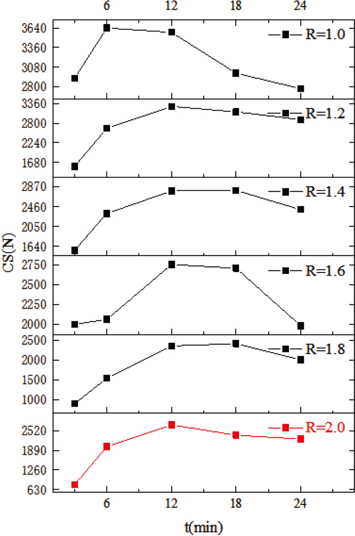
3.2. Influence of Sintering TimeThe samples were roasted under T=1300°C and R=1.0–2.0 conditions at 3, 6, 12, 18 and 24 min sintering time. The compressive strength (CS) of the samples was then measured after cooling, and the results were shown in Fig. 8. As t increases, the compressive strength showed an overall trend of increasing and then decreasing at different R. The samples with R=2.0 were selected for further study to consider the actual sintering production. The compressive strength of the samples reached a maximum value of about 2703 N at t=12 min.
The macroscopic morphology of the samples was shown in Fig. 9(a). At t=3–12 min, the samples changed from sparse and porous to dense, corresponding to an increase in compressive strength. At t=12–24 min, the pores in the specimens gradually became larger and more numerous, gradually formed a thin-walled structure with large pores, resulting in sintering and a decrease in compressive strength.

The microscopic morphology of the samples was shown in Fig. 9(b). At t=3 min, the hematite phase was mostly present as anhedral crystals and subhedral crystals. The calcium ferrite had not yet fully crystallised and was wrapped around the outside of some of the hematite. The compressive strength of the sample at this time was low, 780 N, due to the poor structure.
At t=6 min, a small amount of hematite began to appear as euhedral crystals, most of which were platelets and granules, acicular calcium ferrite was well crystallised and densely distributed, and locally sporadic hematite was infiltrated into the calcium ferrite. At this time the compressive strength of the sample was increased to 2012 N by the presence of acicular calcium ferrite.32)
At t=12 min, most of the hematite began to form plate and granular structures, the amount of acicular calcium ferrite decreases slightly, and the calcium ferrite tightly gelled the hematite, with local granular hematite encapsulated by the calcium ferrite. The compressive strength of the corresponding sample reached about 2703 N.
At t=18 min and 24 min, as the sintering time increases, some of the hematite recrystallises and the fine grains aggregated into coarse grains based on the original mineral crystals. At this point the crystal structure was loose, the crystals were bonded together by the glass phase and the compressive strength is poor. Due to the long sintering time, the calcium ferrite decomposed into small amounts of euhedral crystals and subhedral crystals of magnetite interspersed in the hematite. The compressive strength began to decrease, eventually reached 2250 N.
The variation of the statistical calcium ferrite content (CFC) and porosity of the samples at different t was analysed using ImageJ and the results were shown in Fig. 10. As t increased in 0–18 min, the calcium ferrite content tended to increase and then decrease, while the porosity tended to decrease and then increase. At t=6 min, the calcium ferrite content reached a maximum value of 41.23% and the porosity reached a minimum value of 42.04%, the compressive strength at this time was about 2000 N. At t=12 min, the calcium ferrite content decreased to 20.45% and the porosity increased to 54.35%, the compressive strength at this point was about 2703 N.

In summary, the influence of t on the solidification of sintered ores in the carbon-free sintering process was also reflected in the mineral structure and the liquid phase. In the theoretical calculations, FactSage8.1 cannot calculate the effect of t on the theoretical volume of the liquid phase and the viscosity of the solid-liquid mixed phase. However, at sufficient T, t is closely related to the change of hematite from anhedral crystal to euhedral crystal to recrystallisation, the change of calcium ferrite from erosion structure to needle-like structure to decomposition, and most of the pores in the samples vary from small irregular pores to medium irregular pores to large regular round pores. Therefore, controlling the right time in the actual process will not only increase the yield but also form the required mineral structure to ensure strength.
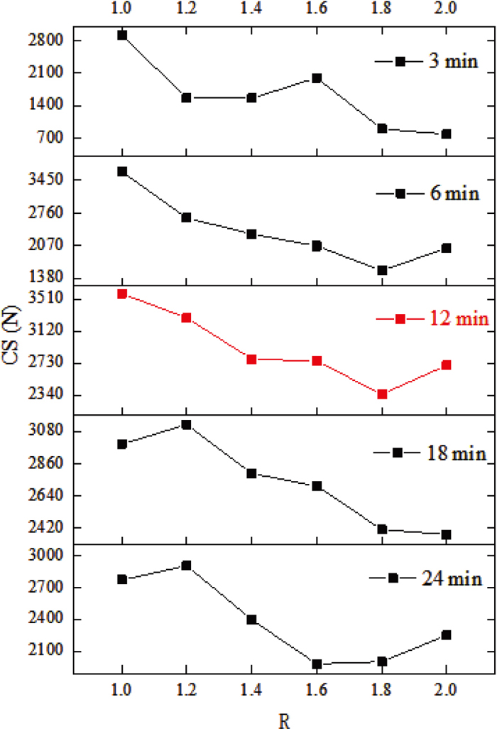
3.3. Influence of Binary BasicityThe samples were roasted under conditions of T=1300°C and t=3–24 min at binary basicity of 1.0, 1.2, 1.4, 1.6, 1.8 and 2.0. The compressive strength (CS) of the samples was then measured after cooling and the results were shown in Fig. 11. As R increases, the compressive strength showed an overall trend of decreasing at different t. The samples at t=12 minutes were selected for further investigation as the samples had an overall higher compressive strength (CS). At this time, the compressive strength tended to decrease overall, but increase slightly at R=2.0.
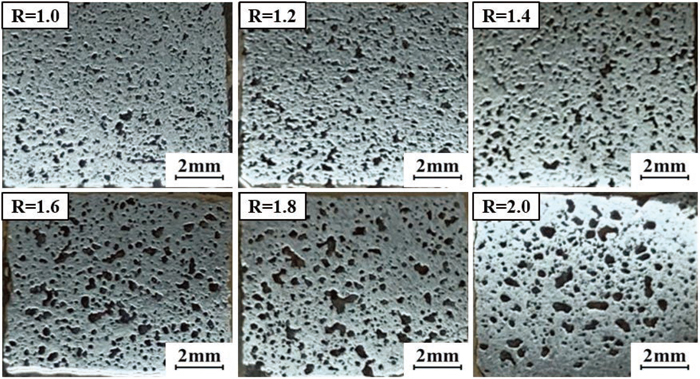
The macroscopic morphology of the specimens was shown in Fig. 12. The holes were more evenly distributed. However, as the R of the specimens increases, the hole size became progressively larger and the shape was still irregular.
The microscopic morphology of the samples was shown in Fig. 13. At R=1.0–1.6, kirschsteinite was cemented in the interstices of the hematite grains, the strength of the sample with this structure was high. The high calcium kirschsteinite and silicate were formed, which had low strength, due to the content of CaO increases. And the microscopic morphology of the acicular calcium ferrite phase did not appear. The sample at R=1.8 started to produce a small amount of acicular calcium ferrite, but the overall structure was still loose. The sample at R=2.0 had more acicular calcium ferrite. And this type of calcium ferrite with the better crystallised hematite, they formed a strong mineral structure.

Using the FactSage 8.1 to calculate the amount of theoretical liquid phase and viscosity at different R, the results were shown in Fig. 14. As R increases, the amount of theoretical liquid phase (ATLP) increases, and the increased liquid phase consisted mainly of Fe2O3, CaO and FeO, but the viscosity decreased.

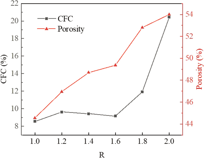
The variation of calcium ferrite content (CFC) and porosity of the samples under different R were analysed using ImageJ image analysis software, and the results were shown in Fig. 15. The calcium ferrite content and porosity showed an overall increasing trend with increasing R, reaching a maximum value of 20.45% and 54.35% at R=2.0 for both calcium ferrite content and porosity respectively.
In summary, the effect of R on the consolidation of sintered ore formation by the carbon-free sintering process was reflected in the mineral consolidation mode and the liquid phase. In theoretical calculations, with increasing basicity, Fe2O3, CaO and FeO participated in the mineralisation reaction to form more calcium ferrite liquid phase in accordance with the trend of the statistical calcium ferrite content, and the viscosity of the solid-liquid mixed phase decreases, leading to better fluidity of the liquid phase, which facilitated the fusion and growth of bubbles. Also, the Ca(OH)2 produced by the digestion of the added CaO will decompose, leaving some holes when preheated.33) As a result, the overall porosity increased with increasing R. However, at R=1.0–1.6, the crystalline form of hematite did not change significantly and the calcium ferrite content was very low and the edges of the hematite were mainly consolidated by the solid phase of silicates. At R=1.8–2.0, acicular calcium ferrite started to appear and increases. The pores of the samples ranged from small irregular pores to medium irregular pores without larger regular round holes. Therefore, controlling the suitable basicity in the actual process not only created the required mineral structure to ensure strength, but also controlled the calcium ferrite content to improve the metallurgical properties of the mineral.
Under carbon-free sintering conditions, the following conclusions were reached.
(1) The sample strength increases and then decreases with increasing sintering temperature and time, reaching maximum values at 1300°C and 12 min respectively, and decreases and then increases with increasing R, reaching a minimum value at 1.8. The above process parameters can be used as a guide for the design of extended test facilities.
(2) The behaviour of the mix without carbon allocation does not affect the method of consolidation of the mineralisation. The microstructure of the high strength sample consists mainly of low calcium cherry stone cemented between low basicity hematite grains and monocalcium ferrite cemented between high basicity hematite grains.
(3) The low basicity samples can achieve higher strength in a shorter sintering time compared to the high basicity samples, thus providing the possibility of subsequent carbon-free sintering of the double basicity material layers. This means that the low basicity blend material could be used in the bottom layer because the sintering time of the bottom layer is shorter than that of the top layer due to the heat transfer efficiency.
(4) As the sintering time or temperature increases, the amount of calcium ferrite increases and then decreases and it is negatively correlated with the change in porosity; as the effect of basicity increases, the amount of calcium ferrite gradually increases and it is positively correlated with the change in porosity.
The author declare that they have no known competing financial interests or personal relationships that could have appeared to influence the ork reported in this paper.
The authors are gratefully for the financial supports provided from China Baowu Low Carbon Met-allurgy Innovation Foudation (No. BWLCF202107), Hubei province scientific research plan guidance project (No. B2022014) and Key Research and Development Program of Hubei Province (No. 2022BCA062). We are also thankful to the Analysis and Test Center, Wuhan University of Science and Technology, which supplied us the facilities to fulfil the measurement.
T: Sintering temperature (°C)
t: Sintering time (min)
R: Binary basicity
CS: compressive strength (N)
ATLP: amount of theoretical liquid phase (%)
CFC: calcium ferrite content (%)