Abstract
The impeller blade structures are developed to maximize reagent utilization in the desulfurization process of molten iron by Kambara Reactor stirring method. Compared the flow structure and mixing effect of four impeller systems by numerical simulation. The distribution and motion behavior of desulfurizer particles are further discussed. In addition, the effect of rotation speed on mixing ability is illuminated. The results show that changing the central structure of the traditional impeller can effectively improve the flow field, changing the width of the asymmetrical impeller blades can enhance the involvement ability, and setting the downward angle on the basis of changing the width of asymmetrical impeller blades can obviously improve the mixing effect in the region under the impeller. The recommended rotation speed is 80 rpm, under actual operation conditions, since it may cause the overflow of molten iron when the rotation speed exceeds 80 rpm.
1. Introduction
Desulfurization of the Kambara Reactor (KR), which has the dominance of high efficiency and a favorable desulfurization ratio, has been a hot investigation spot in recent years.1) In KR desulfurization, lime is commonly used as a desulfurization flux. However, the agglomeration of lime powders in the KR stirring process reduces the reaction contact interface area, resulting in the exclusion of the majority of the lime from the reaction. As a result, the lime is squandered, and the lime utilization ratio is low. Typically, the economic cost of desulfurization flux accounts for 80% of the total economic cost of the desulfurization process.2) Therefore, it is critical to maximize the use of desulfurization flux and increase the lime utilization ratio in order to reduce the economic cost of KR desulfurization.
The experimental parts of the KR process have been the subject of numerous researches, such as impeller practice,3,4,5,6) particle addition mode,7,8) operation parameter improvement,9,10,11) stirring mode change,1,6,12,13,14) and the addition of barriers (such as baffle or pin fins)6,15,16) in the molten pool. The issue of low desulfurization usage rate has made significant progress, but some of the results are challenging to apply in desulfurization practice, which severely restrains the advancement of reagent efficiency. In fact, the flow pattern is critical to ensuring high desulfurization quality of desulfurization, and the impeller is the power source of the desulfurizer and molten iron mixture in the KR method, which plays a decisive role in the flow structure of molten iron and the mixing strength of molten iron and desulfurizer. In-depth research into the impeller structure is required.
Ouyang et al.17) investigated the mixing effect of three-blade impeller for the KR method with a water model and discovered that costs are reduced while desulfurization efficiency is guaranteed. Shao et al.18) studied the effects of a sloped swept-back blade impeller with a thin disc above it on bubble’s dispersion ability in the molten pool through a water model, and concluded that this type of impeller can better disperse bubbles. However, the impeller of three-blades sustained greater force and it is easy to wear; the sloped swept-back blade impeller is complex and thin disc is difficult to be coated with refractory material, so, it is not suitable for working under high temperature environment of molten iron. Furthermore, it is difficult to scale up the results of the water model to the actual equipment because of the nature difference between the water model and the high temperature of molten iron. In contrast, more literatures concentrate on altering the impeller structure under actual operating situations. Zhang et al.19) proposed a Y-shaped impeller to investigate the motion and dispersion characteristic of modifier particles in hot slag with mechanical stirring. By comparing the stirring of the Y-shaped impeller with that of the cross-shaped impeller, they found that the Y-shaped impeller stirring generates a lower axial circulation velocity of hot slag near the impeller and a higher surface-averaged turbulent kinetic energy. After 3 s stirring, the effect of particle dispersion with cross-shaped impeller is better than Y-shaped impeller, and the dispersion of particles is more even in each region. Liu et al.20) studied the effects of sloped swept-back blade impeller with the different size of impeller center region on bubble dispersion and disintegration, and the results showed that the sloped swept-back blade impeller with the bigger size of the center region achieves the most desirable effect of bubble dispersion and disintegration. In addition, this impeller had the highest volumetric mass transfer coefficient and CO2 gas utilization, while maintaining the lowest power consumption. Nevertheless, little attention has been paid to the role of impeller structure on desulfurizer motion behavior and quantitative distribution with the mixing time in the KR process.
Therefore, using molten iron as the research object, under reasonable conditions, four impeller types that meet operational requirements and have outsourced refractory materials have been developed in this work. The first type of impeller is the traditional central structure impeller, and the second type of impeller changes the central structure of the first type to become an asymmetrical impeller. The third type of impeller changes the width of the impeller blades based on the asymmetrical impeller. The fourth type of impeller sets a downward angle based on the changed width of the impeller blades. The effect of the structural parameters of impellers on the flow characteristics of molten iron is investigated compared with the conventional structure of the cross impeller (impeller A). Numerical simulation of the mixing behavior of molten iron and desulfurizer provided a theoretical foundation for the design and improvement of desulfurization mixing equipment.
2. Model Building
2.1. Assumptions
The following assumptions were used for the simplification of numerical model:
(1) The influence of slag was ignored and only the mixing characteristics of molten iron and desulfurizer were considered.
(2) The temperature drop of molten iron was ignored and it was regarded as an isothermal process.
(3) The effect of desulfurization reaction and mass transfer were not considered.
2.2. Continuous Phase Hydrodynamics
In this work, the continuous phase in the ladle is considered to be molten iron and air. The three-dimensional unsteady incompressible mixed fluid in the impeller-stirred vessel was analyzed numerically by VOF (Volume of Fluid) method. The equations of continuity and motion which control the fluid flow are expressed by Eqs. (1) and (2), respectively.
|
∂(ρu)
∂t
+∇(ρuu)=-∇p+∇(μ∇u)+ρg+
F
σ
+
F
other
| (2) |
|
F
σ
=2σ
ρk∇α
ρ
l
+
ρ
g
| (4) |
where,
ρ is the mean density (kg/m
3),
ρl,
ρg denote liquid-phase of molten iron density and gas-phase of air density, respectively.
u is the velocity vector,
p is the pressure (Pa),
g is the gravity acceleration vector,
Fσ is the gas-liquid surface tension using the continuum-surface-force (CSF) model developed by Brackbill
et al.,
21) and
σ is the surface tension coefficient set as 1.8 N·m
−1.
Fother is the interaction momentum per unit mass transferred from the discrete phases.
αi is the volume fraction of molten iron (subscript l), air (subscript g). The sum of the volume fractions of the
i phase equals 1 as expressed by
Eq. (5), and the transport equation of each volume fraction of
i is given by
Eq. (6).
|
∂(
α
i
ρ
i
)
∂t
+∇(
α
i
ρ
i
u)=0
| (6) |
To model the turbulent viscosity in the liquid phase, Realizable k–ε models were adopted as Eqs. (7) and (8),
|
∂
∂t
(
ρ
l
k)+
∂
∂
x
i
(
ρ
l
k
μ
l,i
)=
∂
∂
x
j
(
λ
l
+
μ
t,l
σ
k
+
∂k
∂
x
j
)
+
G
k
-
ρ
l
ε
| (7) |
|
∂
∂t
(
ρ
l
ε)+
∂
∂
x
i
(
ρ
l
μ
l,i
ε)=
∂
∂
x
j
(
λ
l
+
μ
t,l
σ
ε
+
∂ε
∂
x
j
)
+
ρ
l
C
1
Eε
-
ρ
l
C
2
ε
2
k
l
+
ν
l
ε
| (8) |
|
μ
t,l
=
C
μ
ρ
l
k
2
ε
C
1
=max(
0.43,
η
η+5
)
η=
(2
E
ij
⋅
E
ij
)
1/2
k
ε
E
ij
=
1
2
(
∂
u
i
∂
x
j
+
∂
u
j
∂
x
i
)
G
k
=
μ
t,l
(
∂
u
i
∂
x
j
+
∂
u
j
∂
x
i
)
∂
u
i
∂
x
j
}
| (9) |
where
k,
ε,
υl,
Gk and
μl are the turbulent kinetic energy, turbulent dissipation rate, motion viscosity, generating term of the turbulent kinetic energy caused by the average velocity gradient, and molecular viscosity of liquid phase, respectively.
Cμ,
C2,
σk,
σε are empirical constant, the values recommended by Launder and Spalding
22) are adopted
Cμ = 0.09,
C2 = 1.93,
σk = 1.00,
σε = 1.30.
2.3. Discrete-phase Dynamics
The desulfurizer particles were regarded as a discrete phase, which motion was governed by Newton’s second law
|
m
d
d
v
d
dt
=
F
d
+
F
g
+
F
b
+
F
p
+
F
vm
| (10) |
where
md, and
vd are the discrete-phase mass and velocity, respectively.
Fd,
Fg,
Fb,
Fp, and
Fvm on the right-hand side of the above equation (in the order of their appearance) are the drag force, gravity force, buoyancy force, pressure gradient force and virtual mass force, respectively. The drag force is given by
|
F
d
=
C
d
ρ|
v-
v
d
|(v-
v
d
)
2
π
d
d
2
4
| (11) |
The drag coefficient Cd was modelled by using Gidaspow model23) as given below,
|
C
d
={
24
Re
s
[1+0.15
(
Re
s
)
0.687
] for
Re
s
≤1 000
0.44 for
Re
s
>1 000
| (12) |
where Re
s is the Reynolds number, and Re
s =
αlρlds|
us−
ul|/
μl.
The gravity force is given by
|
F
g
=
1
6
π
d
d
3
ρ
d
⋅g
| (13) |
The buoyancy force is given by
|
F
b
=
1
6
π
d
d
3
ρ⋅g
| (14) |
The buoyancy force coefficient is calculated using Saffman-Mei model.24)
The pressure gradient force is given by
|
F
p
=
π
6
ρ
d
d
3
v
d
∇v
| (15) |
The virtual mass force is given by
|
F
vm
=
π
6
ρ
d
d
3
C
vm
(
v
d
∇v-
d
v
d
dt
)
| (16) |
The virtual mass force coefficient is used as 0.5 according to He et al.12) And the random walk model25) was invoked to assess the particle interaction with continuous phase turbulent eddies. The trajectories of particles were achieved by integrating Eq. (17).
2.4. Physical Model
A 260 ton ladle of a steel plant was taken as the prototype, and the ladle was simplified into a trapezoidal cylindrical container, which contains 1300°C molten iron. After the molten iron reaches a steady state, 4246 calcium oxide desulfurizer particles were laid above the molten iron surface with the injection diameter of 3 m, at the position of Z = 3.4 m. The impeller shaft was coincided with the ladle axis and plunged vertically into the molten iron with the impeller immersion depth of 1.3 m. The stirring system diagram is shown in Fig. 1, the main parameters of model are listed in Table 1.
Table 1. Parameters of physical model.
| Parameter | Value |
|---|
| Bath mouth diameter I1 (m) | 4 |
| Bath bottom diameter I2 (m) | 3.5 |
| Bath height H (m) | 4.5 |
| Molten iron surface height M (m) | 3.3 |
| Impeller immersion depth N (m) | 1.3 |
| Impeller height W (m) | 0.7 |
| Molten iron density (kg/m3) | 7800 |
| Molten iron viscosity (Pa∙s) | 0.0063 |
| Desulfurizer particle density (kg/m3) | 3320 |
| Desulfurizer particle diameter (m) | 0.001 |
| Rotation speed (rpm) | 60–90 |
Four concise impellers covered with refractory materials have been designed to withstand the severe circumstances of high temperature and corrosion. The four types of impellers and dimension are shown in Fig. 2. The flow state of the fluid on the back of the blades would be improved by setting a special-shaped structure at the center of the blades (the impeller B with wider blades of asymmetrical structure and impeller C with thin blades of asymmetrical structure). The molten iron diffusion ability around the blades would be increased by setting the downward angle on the basis of the thin blades of asymmetrical structure (the impeller D). And the four impellers rotate counterclockwise with the same blade length.
2.5. Numerical Details and Boundary Conditions
The commercial software ANSYS Fluent version 2020R2 was used to calculate the mixing process in this work. After the grid independence test, the total number of grid cells was set to about 380000 depending on the impeller shape, in order to achieve a reasonable balance between the computational cost and accuracy. VOF two-phase flow approach was adopted by implicit separation method. The multiple reference frame method was used to simulate the flow field. Cell zone was divided into an inner domain and an outer domain. The outer region was solved in the stationary reference, while the inner domain, including the impeller, was solved in the rotating reference and the rotation speed was set, the value would match at the interface of the two grids regions. In the two-phase flow settings, the molten iron was set as the primary phase and the secondary phase was the air, the discrete phase was the calcium oxide particles. Besides, the top surface of the ladle was set as the boundary conditions of outflow, and the ladle wall, impeller wall including shaft wall were set as no-slip wall with the standard wall function. Momentum, turbulent kinetic energy, and turbulence dissipation were used in the second upwind scheme, and the SIMPLE algorithm was used for pressure-velocity coupling. The time step is set as 0.01 s, and the criterion for calculating convergence was that the residuals of all detected parameters were 10−6, respectively.
3. Model Validation
In order to confirm the reliability of the current simulation results, a comparison was done with the experimental and simulation results of reference [9]. The condition of the simulation was the same as the previous water model using mechanical stirring, which was mentioned by reference [9]. Figure 3 compares the vortex surface and particle distribution in a water model and numerical simulation results with different rotational speeds and immersion depths. The simulated interface shape, as derived through the proposed model, is in good agreement with the observed interface shape in the water model experiment. As the rotational speed increases, the particles tend to encounter the interface and disperse in the water. Additionally, at greater immersion depths, more particles are likely to settle at the bottom of the vessel.

Figure 4 depicts the vortex depth and height values obtained at various immersion depths and rotational speeds. It can be seen that the maximum error between the calculated values of vortex depth and vortex height in Ref. [9] and those in this work are less than 5%, which indicate that the calculated results in this work are reliable.
4. Results and Discussion
4.1. Effect on Flow Structure of Molten Iron
Figure 5 shows the velocity distribution, streamlines and vortex surface of molten iron along longitudinal section of each impeller system when the flow reached a steady state under the condition that the rotation speed is 80 rpm. It is found that the flow of the molten iron all presents a symmetrical structure in four different types of impeller systems. Due to the agitation force, some circulation streams of varying sizes appear in the molten iron beneath the vortex surface, facilitating the mixing of molten iron and desulfurizer. The flow patterns of these circulation streams fall into two categories, one is above the impeller which circulates upward and one is below the impeller which circulates downward. It can be seen that in the flow field of asymmetrical structure impeller type (impeller B), the blades break up the original circulation stream structure making the circulation streams significantly smaller and the distribution of the molten iron around the impeller more uniform. Although changing the width of the blades with an asymmetrical structure impeller does not change the flow field considerably compared to the flow field with the asymmetrical structure impeller, this type of impeller (impeller C) enhances the involvement ability, which will be discussed in the next section. Setting the downward inclination angle on the basis of impeller C obviously improves the flow field distribution, not only the number of circulation streams is reduced by two, the size of circulation streams also become smaller, and the distribution of iron is more even. This is because when the blade rotates counterclockwise, the fluid in front of the blade is thrown out, and an oblique downward velocity component is given to it, which enhances the downward entrainment effect and improves the dynamic conditions of the lower half of the flow field to some extent. The results show that the flow structure under the stirring mode of traditional impeller would be improved either by changing the center shape of the impellers, changing the width of the blades, or setting the downward angle of the blades.

It is noted that there is a low-speed zone (the maximum velocity less than 1.4 m∙s−1) under the impeller which makes the molten iron flow in this zone inactive, and the low-speed zone is called the dead zone. Compared with the traditional impeller A, the flow of molten iron under the impeller of the impeller B and C systems is more chaotic, and the dead zone of molten iron under the impeller D systems is smaller and the shape of dead zone is triangular. So, the distribution of desulfurizer in molten iron will be more uniform and more extensive by using the new types of impellers.
4.2. The Effect of Impeller Shape on Turbulent Dissipation Rate Distribution
Momentum diffusion is generally classified into molecular diffusion and turbulent diffusion, with the latter being the primary cause of concentration diffusion, momentum exchange, and heat exchange between desulfurizing agents and molten iron. Reynolds26) proposed the Reynolds analogy in 1874, elucidating the analogous relationship between concentration diffusion and eddy viscosity, expressed by Eq. (18). The energy consumption caused by eddy viscosity can be approximately regarded as proportional to the turbulent dissipation rate.
|
D
r
=-
q
∂C
∂r
∝
υ
t
=
τ
∂(ρu)
∂r
| (18) |
Where Dr is radial mass diffusion coefficient (m2/s), q is the diffusivity along the radial direction of a mass concentration of C (kg/(m2·s)), C is substance concentration (kg/m3), υt is the eddy viscosity which can be understood as momentum diffusion coefficient (m2/s), τ is the Reynolds stress on the fluid, which is the change rate of momentum in the radial direction (kg/(m·s2)). ρu is momentum (kg/(m2/s)). From Eq. (18), it can be observed that as the eddy viscosity increases, the radial turbulent diffusion coefficient of the substance also increases. Therefore, the magnitude of turbulent dissipation rate at the molten iron surface can reflect the ability of the desulfurizer to be involved. The greater the turbulent dissipation rate, the better the involvement effect. Figure 6 shows the radial distribution of turbulent dissipation rate at liquid surface with a rotational speed of 80 rpm. The vortex core is located at the point where the distance is 0. The turbulent dissipation rate from the vortex core to the wall has a similar trend of initially decreasing and then increasing and decreasing again for different types of impeller blades. The trend of changes in impeller C is the most significant, and its numerical value is higher than the other three impellers. Impeller B and D have similar trends of change, and their numerical value are slightly higher than impeller A. This indicates that the involvement ability of impeller B, C and D is stronger than that of impeller A, with impeller C being the most effective.

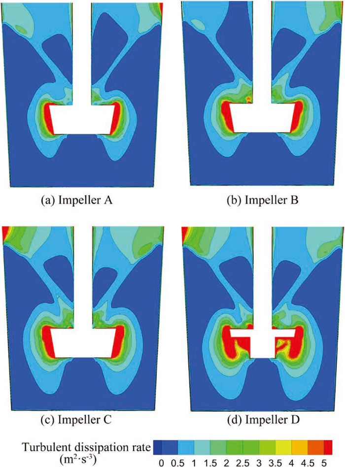
Figure 7 illustrates the distribution of turbulent dissipation rate within the melt at a rotational speed of 80 rpm. It can be observed that in the region at both ends of the impeller, the use of a noncentral structure impeller generates significant mixing forces, resulting in enhanced mixing capabilities within the region. The vortex area of impeller B, C, D is larger than that of impeller A, with impeller D having the highest numerical value due to its downward inclination angle, which provide the best mixing effect. The axial variation of turbulence dissipation rate of impeller D almost reaches the bottom of the melt, which facilitates the suction of desulfurizer towards the lower impeller region.
4.3. Mixing Effect of Different Impeller System
In order to make a quantitative comparison of distribution of particles within molten iron, the complete computational basin has been partitioned into six regions. These regions are denoted as Internal I1, I2 and I3, as well as External O1, O2 and O3, and have been divided via two planes at different heights, Z = 1.2 m and Z = 2.1 m with the blade radius serving as the dividing line, as shown in Fig. 8. The definition of the particle volume fraction is the percentage of the current regional desulfurizer to the total input desulfurizer volume. During the calculation process, the particle volume fraction in these six regions is monitored. After the distribution of desulfurizer is stable, the particle volume fraction is separately calculated. Based on this, the desulfurization effect of different structured impeller is compared. The operating condition is that the rotation speed is set as 80 rpm.

Nakai et al.8,27) reported that both powder blasting and avoiding particle aggregation are advantageous for improving desulfurization efficiency, based on an investigation of flux dispersion behavior in hot metal desulfurization with mechanical stirring. Wang et al.28) investigated the hot metal desulfurization behavior and mass transfer by establishing a transient coupled 3D numerical model incorporated a desulfurization kinetic model. And they found that the sulfur content is the highest in the inactive colder liquid metal at the vessel bottom due to the weak flow. In summary, this work posits that the distribution of desulfurizer particles in areas with poor stirring or inactive is conducive to enhancing desulfurization efficiency. The desulfurizer encounters difficulty in penetrating the “dead zone” directly beneath the mixing blades, thereby weakening its desulfurization effect. Consequently, this work employs the particle volume fraction in region I3 as one of the criteria for evaluating the effectiveness of impeller mixing.
Figure 8 compares the particle volume fraction of desulfurizer in various regions under four different impeller types when the basic steady state is reached. The desulfurizer in the iron ladle under the four impeller systems is mainly concentrated in the O1 region, while the desulfurizer volume fraction is relatively low in the I1 region due to the majority of its area being located within the vortex formed at the air-steel interface. The difference in volume fraction of desulfurizer using A-type impeller blades between region O2 and region I2 is negligible. However, the volume fraction of desulfurizer in region I3 is the least among the four impeller systems, amounting to only 4.07%. In the impeller C system, the volume fraction of desulfurizer in the O1 region is the highest among the four impeller systems. In the context of using the impeller D, the volume fraction of desulfurizer in region I3 is superior to the other three impeller system. This indicates that using the impeller D is more advantageous for the uniform distribution of desulfurizer. Compared to the results obtained using the impeller A, the volume fraction of desulfurizer in region I3 increased by 11.00% when using the impeller B, increased by 26.61% when using the impeller C, and increased by 72.26% when using the impeller D.
4.4. The Movement and Trajectory of Desulfurizer in Impeller D
It is of great significance to study the particle motion behavior in impeller D system due its excellent entrainment capacity in I3 region. Figure 9 shows the variation of particle distribution of impeller D system with the time under rotation speed of 80 rpm. It can be seen that when t = 1 s, the desulfurizer mostly exists near the liquid surface of molten iron, and the number of particles in the dead zone is 0. At t = 3 s, as the desulfurizer is continuously thrown out from the vicinity of the liquid surface, desulfurizer particles begin to appear around the impeller and in the lower region (including the dead zone), and as the stirring proceeds, more and more desulfurizers are involved in the lower region. At t = 5 s, the number of desulfurizer particles in the lower region increased significantly, and the desulfurizer at the bottom of the molten iron surface began to be thrown out to the tank wall, and the desulfurizer was also sucked into the lower region. At t = 7 s, the desulfurizer around the impeller began to move to the upper region and was sucked near the molten iron surface. At the same time, a small part of the desulfurizer in the lower region began to move to the dead zone. At t = 9 s, 11 s, 13 s, respectively, with the stirring proceeding, the number of desulfurizer particles in the dead zone is increasing, and it can be seen that the movement speed of the desulfurizer in the dead zone is significantly reduced. At t = 15 s, the flow in the molten iron tank reaches a stable state, and the number of desulfurizers in the dead zone increases compared with that at t = 13 s.

Taking the center of the impeller as the origin of the coordinate system, four monitoring points were installed above the impeller with the coordinate of (0, −1.5, 3.4), at the interface between the air and molten iron with the coordinate of (0, −0.2, 0.4), next to the blades with the coordinate of (0, −1.65, 0.1), and in the region beneath the impeller with the coordinate of (0, −1.2, −1.5), respectively, to track the movement trajectory of desulfurizer particles during the desulfurization process, as depicted in Fig. 10, and Figs. 10(a), 10(b), 10(c), 10(d) corresponding to 1 s, 3 s, 7 s, and 9–13 s, respectively, in Fig. 9. It can be seen from Fig. 10 that the trajectory of these four typical desulfurizers conforms to the time-varying distribution of desulfurizers in molten iron. At the beginning of the stirring, the desulfurizer moves toward the vortex core as shown in Fig. 10(a). As the stirring progresses, the desulfurizer at the vortex core continues to move downward, some of the desulfurizer stays around the impeller, and some stays in the lower region of the impeller as shown in Fig. 10(b). Then, the desulfurizer that stays around the impeller is thrown upward as shown in Fig. 10(c), and the desulfurizer that stays in the lower area is drawn into the dead zone as shown in Fig. 10(d). Finally, the distribution of desulfurizer tends to be stable. It is the particle motion trajectory in Fig. 10 that improves the efficiency of desulfurizer in the dead zone. Although the other three types of impellers also have such trajectories, the impeller D is much higher than the other three impellers in the frequency of occurrence.

Figure 11 presents the particle volume fraction in I3 region of four impeller systems under the rotation speed of 60, 70, 80 and 90 rpm, respectively, when the flow reaches stable state. The results show that the desulfurizer volume fraction in I3 region increases with the increase of the impeller rotation speed. The mixing effect of the impeller is sorted according to the impeller D, C, B, A, among which the impeller D has the best mixing effect and the most uniform distribution of desulfurizer particles. The mixing effect of impeller B and impeller C is almost the same before the rotation speed reaches 80 rpm. After the rotation speed reaches 80 rpm, the mixing effect of impeller C is slightly better than that of impeller B, but the mixing effect of impeller B and impeller C is better than that of traditional type of impeller A. Although the results show that the stirring effect is best when the rotation speed is 90 rpm, the rotation speed of 90 rpm is not recommended in this study. The reason is that when the speed reaches 90 rpm, the molten iron may splash to the top edge of the ladle, causing overflow during actual production process as shown in Fig. 12. Therefore, the recommended impeller rotation speed is 80 rpm.


The surface of molten iron forms a constant depth vortex with the constant speed stirring mode, and different types of impellers rotation produce different axial velocities, resulting in different structures and depths of the vortex. The deeper the vortex, the better effect of desulfurizer involved. Figure 12 shows the vortex depth of molten iron with different rotation speed under four impeller systems. At the top of the figure is a schematic diagram of the molten iron vortex depth of the impeller D system under four rotation speeds. The results show that before the rotation speed reaches 90 rpm, the vortex depth of impeller C is the deepest, reaching 2.65 m, followed by impeller D, with a depth of 2.62 m. This indicates that the impellers C and D can generate larger axial velocity to increase the depth of vortexes compared with impellers A and B, and the involvement effect of impeller C is the best. The impeller D has the best effect on improving the dead zone.
5. Conclusion
Four types of impeller blade are developed in order to solve the problem of desulfurizer low utilization rate. The influence of the structure of impeller on the mixing behavior between particles and molten iron is investigated through the flow filed structure, the turbulent dissipation rate, the particle volume fraction distribution and motion, and the rotation speed, respectively. The following conclusions were drawn,
(1) The asymmetrical structure impeller (impeller B and C) and the downward angle of the blades (impeller D) can improve the flow structure of molten iron and the utilization of desulfurizer.
(2) The dead zone area of the impeller with a slope (impeller D) is smaller than that of other impeller systems, which presents triangular, and the distribution of desulfurizer in the impeller D system is more even.
(3) Changing the central structure of the impeller type can improve the turbulent dissipation rate in the molten iron, while changing the width of the asymmetrical structure impeller blade can enhance the involvement ability of the desulfurizer. Setting the downward angle of thin asymmetrical structure impeller blades can facilitate the suction of the desulfurizer towards the lower impeller region.
(4) A better mixing effect can be obtained by increasing the rotation speed. In this work, the mixing effect is the best when the rotation speed is 80 rpm. The vortex depth of impeller C is the deepest, with a depth of 2.65 m.
Acknowledgements
The authors gratefully acknowledge the Education Department of Liaoning Province of China (No. LJ2019JL016) which has made this research possible.
References
- 1) J. Ji, R. Liang and J. He: ISIJ Int., 56 (2016), 794. https://doi.org/10.2355/isijinternational.ISIJINT-2015-549
- 2) S. Wu and J. Yang: Metall. Res. Technol., 118 (2021), 603. https://doi.org/10.1051/metal/2021074
- 3) C. Yin, L. Yang, C. Tian and J. Ma: Iron Steel, 55 (2020), 34. https://doi.org/10.13228/j.boyuan.issn0449-749x.20190065
- 4) L. Xiao, K. Chen, B. Dan, Z. Rong and R. Wang: Adv. Mech. Eng., 8 (2016), No. 7. https://doi.org/10.1177/1687814016649326
- 5) Y. Zhou, Y. Lu, M. Chen and J. Liang: Chin. J. Process Eng., 14 (2014), 744.
- 6) T. Sukawa and M. Iguchi: ISIJ Int., 45 (2005), 1145. https://doi.org/10.2355/isijinternational.45.1145
- 7) Y. Nakai, I. Sumi, N. Kikuchi, K. Tanaka and Y. Miki: ISIJ Int., 57 (2017), 1029. https://doi.org/10.2355/isijinternational.ISIJINT-2017-063
- 8) Y. Nakai, Y. Hino, I. Sumi, N. Kikuchi, Y. Uchida and Y. Miki: ISIJ Int., 55 (2015), 1398. https://doi.org/10.2355/isijinternational.55.1398
- 9) Y. Nakai, I. Sumi, H. Matsuno, N. Kikuchi and Y. Kishimoto: ISIJ Int., 50 (2010), 403. https://doi.org/10.2355/isijinternational.50.403
- 10) R. Tanaka, M. A. Uddin and Y. Kato: ISIJ Int., 58 (2018), 620. https://doi.org/10.2355/isijinternational.ISIJINT-2017-619
- 11) A. Matsui, Y. Nakai, N. Kikuchi, Y. Miki, S. Sato, R. Kawabata and A. Ichikawa: Tetsu-to-Hagané, 99 (2013), 458 (in Japanese). https://doi.org/10.2355/tetsutohagane.99.458
- 12) M. He, N. Wang, M. Chen, M. Chen and C. Li: Powder Technol., 361 (2020), 455. https://doi.org/10.1016/j.powtec.2019.05.056
- 13) F. D. M. Torres, C. A. D. Silva, I. A. D. Silva, P. H. R. V. D. Melo and M. A. Lourenço: Tecnol. Metal., Mater. Miner., 14 (2017), 204. https://doi.org/10.4322/2176-1523.1227
- 14) W. Wu, W. Wu, Y. Hu, L. Liu and Y. Ding: J. Iron Steel Res. Int., 15 (2008), 15. https://doi.org/10.1016/S1006-706X(08)60004-7
- 15) K. Ito, N. Yamamoto and S. Kuranaga: ISIJ Int., 46 (2006), 1791. https://doi.org/10.2355/isijinternational.46.1791
- 16) C. Min, B. Dan, Q. Niu, D. Ouyang and C. Gong: J. Wuhan Univ. Sci. Technol., 43 (2020), 340 (in Chinese). https://doi.org/10.3969/j.issn.1674-3644.2020.05.004
- 17) A. Luo, Y. Ou, M. Li, S. Zhu, Y. Jiang and H. Wang: Res. Iron Steel, 40 (2012), 31.
- 18) P. Shao, T. Zhang, Z. Zhang and Y. Liu: ISIJ Int., 54 (2014), 1507. https://doi.org/10.2355/isijinternational.54.1507
- 19) C. Zhang, N. Wang and M. Chen: ISIJ Int., 61 (2021), 2754. https://doi.org/10.2355/isijinternational.ISIJINT-2021-220
- 20) Y. Liu, Z. Zhang, J. Liu, J. Zhang, M. Sano and J. Zhang: J. Iron Steel Res. Int., 20 (2013), 1. https://doi.org/10.1016/S1006-706X(13)60208-3
- 21) J. U. Brackbill, D. B. Kothe and C. Zemach: J. Comput. Phys., 100 (1992), 335. https://doi.org/10.1016/0021-9991(92)90240-Y
- 22) B. E. Launder and D. B. Spalding: Lectures in Mathematical Models of Turbulence, Academic Press, Cambridge, MA, (1972), 157.
- 23) D. Gidaspow, R. Bezburuah and J. Ding: Proc. 7th Engineering Foundation Conf. on Fluidization, (Brisbane), Engineering Foundation, New York, (1992), 75.
- 24) R. Mei and J. Klausner: Int. J. Heat Fluid Flow, 15 (1994), 62. https://doi.org/10.1016/0142-727X(94)90031-0
- 25) A. D. Gosman and E. Ioannides: J. Energy, 7 (1983), 482.
- 26) Y. Wang, H. Ai, W. Huang and Q. He: Chin. J. Environ. Eng., 9 (2015), 3637.
- 27) Y. Nakai, I. Sumi, N. Kikuchi, Y. Kishimoto and Y. Miki: ISIJ Int., 53 (2013), 1411. https://doi.org/10.2355/isijinternational.53.1411
- 28) Q. Wang, S. Jia, F. Tan, G. Li, D. Ouyang, S. Zhu, W. Sun and Z. He: Metall. Mater. Trans. B, 52 (2021), 1085. https://doi.org/10.1007/s11663-021-02080-2