Abstract
Stress and plastic strain distributions and those partitioning behaviors of ferrite and retained austenite were investigated in the medium manganese (Mn) and the transformation-induced plasticity-aided bainitic ferrite (TBF) steels, and the martensitic transformation behaviors of retained austenite during Lüders elongation and work hardening were analyzed using synchrotron X-ray diffraction at SPring-8. The stress and plastic strain of retained austenite and volume fraction of retained austenite were remarkably changed during Lüders deformation in the medium Mn steel, implying that the medium Mn steel possessed inhomogeneous deformation at the parallel part of the tensile specimen. On the other hand, the distributions of the stress, plastic strain and volume fraction of retained austenite were homogeneous and the homogeneous deformation occurred at the parallel part of the tensile specimen at the plastic deformation regime with work hardening in the medium Mn and TBF steels. The martensitic transformation of retained austenite at Lüders deformation in the medium Mn steel was possessed owing to the application of high stress and preferential deformation at retained austenite, resulting in a significant increase in the plastic deformation and reduction of stress in the retained austenite. The martensitic transformation of retained austenite at the plastic deformation regime with work hardening was induced by the high dislocation density and newly applied plastic deformation in retained austenite in the medium Mn steel whereas the TBF steel possessed gradual transformation of retained austenite which is applied high tensile stress and moderate plastic deformation.
1. Introduction
To achieve a carbon-neutral society, widespread of electrical and fuel cell cars is demanded and an improvement in energy consumption through the reduction of car weight is required. On the other hand, further improvement of the impact safety of the frame parts of vehicles is also required not only for the safety of passengers but also to avoid damage to batteries and hydrogen fuel cells. Ultrahigh-strength steels with tensile strengths of 1500 and 1800 MPa grades have been adopted in automobile frame parts to achieve excellent impact safety.1,2)
From the viewpoint of productivity, advanced high-strength steels (AHSS) with a superior strength-ductility balance of 20–30 GPa% are being developed because automobile frame parts are produced by cold-press forming using 1500 MPa grade ultrahigh-strength steels. Because medium manganese steels3,4,5) composed of a dual-phase microstructure of ferrite and austenite and transformation-induced plasticity-aided bainitic ferrite (TBF) steels6,7,8,9) with a dual-phase microstructure consisting of bainitic ferrite and retained austenite exhibit a high tensile strength of more than 980 MPa and excellent ductility of more than 20%, they are expected to be applied as third-generation AHSS.
The medium manganese steels with a microstructure of fine grains of ferrite and retained austenite were produced by intercritical annealing using Fe–C–Mn steel sheets with the addition of 5 mass%Mn.10,11) The stress-strain curves of medium manganese steels are characterized by Lüders elongation immediately after yielding and work hardening accompanying serration (dynamic strain aging).12,13) The Lüders deformation behavior has been analyzed in detail using digital image correlation (DIC),11,14,15) synchrotron X-ray diffraction13,16,17) and in situ tensile test-microstructure observation using scanning electron microscopy (SEM).18,19) Macroscopic inhomogeneous deformation behavior, transformation behavior of retained austenite, and microscopic deformation and transformation behaviors have been revealed. Wang et al.20) visualized the propagation behavior of the Lüders band using DIC in medium manganese steel and revealed that a large amount of plastic strain was applied at the Lüders deformation portion, although plastic deformation hardly occurred at the portion where the Lüders deformation did not occur. Furthermore, Han et al.21) investigated the distribution of the volume fraction of retained austenite at the parallel part of a tensile specimen using X-ray diffraction and reported that the volume fraction of retained austenite at the portion where Lüders deformation occurred significantly decreased in comparison with that in the non-deformed portion. In addition, Koyama et al.18,19) analyzed microstructural changes in front of the Lüders front at the micro level using an in situ tensile test-microstructure observation technique in SEM and revealed that retained austenite was preferentially deformed; the transformation of retained austenite occurred as austenite (face-centered cubic: FCC) → ε martensite (hexagonal close-packed: HCP) → α’ martensite (body-centered cubic: BCC/body-centered tetragonal: BCT), and plastic deformation was not applied to both the ferrite and austenite phases at the portion where Lüders deformation did not occur. Conversely, Zhang et al.13,17) carried out the in situ tensile test-synchrotron X-ray diffraction measurement and reported the change in the volume fraction of retained austenite and the stress partitioning behavior between ferrite, retained austenite, and deformation-induced martensite.
In contrast, the TBF steels were produced by annealing at austenitic region and austempering treatment using a cold-rolled steel sheet with a chemical composition of Fe-(0.1-0.6)C-1.5Si-1.5Mn (mass%), and the TBF steels possessed the microstructure consisting of bainitic ferrite matrix and film-type retained austenite. The stress-strain curves of the TBF steels were characterized by continuous yielding behavior. The martensitic transformation behavior of the retained austenite,22,23) plastic strain evolution behavior24,25,26) and stress and plastic strain partitioning behaviors24,27) in TBF steels have been investigated. Tsuchida et al.28,29) investigated the transformation behavior of retained austenite and the stress partitioning behavior between ferrite, austenite, and martensite during tensile tests in low-alloy TRIP-aided steels with different retained austenite morphologies and reported that the martensitic transformation of retained austenite gradually occurred in the low-alloy TRIP-aided steel with needle-like retained austenite, and the martensitic transformation of needle-like retained austenite was suppressed until high stress was applied to the needle-like retained austenite.
Because transformation occurs during tensile test in medium manganese and TBF steels containing retained austenite, the Lüders deformation behavior, work hardening behavior after Lüders deformation, martensitic transformation behavior of retained austenite, and stress and plastic strain partitioning behaviors should be considered to understand the superior mechanical properties of these steels. It is possible to simultaneously analyze the martensitic transformation behavior of retained austenite and the stress and plastic strain partitioning behaviors using in situ tensile test-synchrotron X-ray diffraction measurements at SPring-8. Hojo et al.16) investigated in situ synchrotron X-ray diffraction measurements during the tensile test of medium manganese and TBF steels with similar tensile strengths and elongations, and the martensitic transformation behavior and stress and plastic strain partitioning behaviors between ferrite and austenite were analyzed and compared. In this measurement, the stress and plastic strain distribution and partitioning behaviors between ferrite and austenite at the parallel part of the tensile specimen during inhomogeneous deformation, such as Lüders deformation, were unclear. In this study, the stress and plastic strain distribution and partitioning behaviors between ferrite, austenite, and martensite and the distribution of the volume fraction of retained austenite in medium Mn and TBF steels were investigated, facilitating the in situ tensile test-synchrotron X-ray diffraction measurement at SPring-8. The effects of martensitic transformation of retained austenite on the Lüders deformation and work hardening behaviors are discussed.
2. Experimental Procedure
In this study, the 5 mass%Mn-medium manganese (Mn) steel (hereafter medium Mn steel) was produced by an intercritical annealing at 650°C for 1800 s following air cooling of a cold-rolled steel sheet with a chemical composition of 0.092C-0.04Si-4.91Mn-0.024Al-0.005O-0.001N (mass%), and a cold-rolled steel sheet of a chemical composition of 0.401C-1.52Si-1.52Mn-0.051Nb-0.21Mo-0.0006O-0.019N (mass%) was annealed at 900°C for 1200 s and austempered at 400°C for 500 s to produce the TBF steel. In situ tensile test-synchrotron X-ray diffraction measurements were performed on beamline BL14B1 at SPring-8 using white X-rays and a germanium detector. The synchrotron X-rays on the incident side were limited using a slit set with a 0.3 mm height and 0.05 mm width, and the X-rays penetrating through the specimen were shaped on the detection side using a tapered collimator of 50 μm on the incident side and 200 μm on the emitting side and a slit of 5 mm height and 0.05 mm width. The diffraction angle of the detector was set at 10.23°. The diffraction peaks of αFe321 and γFe311 obtained by the synchrotron X-ray diffraction in the tensile direction were adopted to analyze the elastic strain (i.e. stress) and plastic strain in the tensile direction. In addition, the quantification of volume fraction of retained austenite was conducted using the diffraction peaks of αFe200, αFe211, αFe220, γFe200, γFe220 and γFe311. These diffraction peaks were approximated using a Gaussian function, and peak-center energy, full width at half maximum (FWHM), and integrated intensity of the peaks were calculated. It is known that Bragg’s law is defined as Eq. (1), in which λ is the wave length of X-ray. Moreover, the relationship between wavelength (λ) and energy (E) is defined in Eq. (2).30)
where θ, d, h and c denote diffraction angle, lattice spacing, Planck constant, and the speed of light in vacuum, respectively. According to Eqs. (1) and (2), the lattice spacing increases with decreasing energy. That is, the peak-center energy of the diffraction peak shifts toward the low-energy side and the lattice spacing increases when tensile stress is applied. The elastic strain (εe) of each diffraction peak was calculated using following Eq. (3) of the rate of change in the lattice spacing analyzed from diffraction peak-center energy.
|
ε
e
=(
d
t
-
d
0
)/
d
0
| (3) |
where d0 and dt represent the lattice spacings before and during the tensile tests, respectively. The plastic strain was evaluated using the FWHM of each diffraction peak. The volume fraction of retained austenite was calculated from the ratio of the integrated intensity of diffraction peaks between ferrite and austenite. In the medium Mn steel, the peak-center energy and FWHM of martensite were also analyzed because it was possible to deconvolute αFe321 diffraction peak to the peaks of ferrite and martensite which is transformed from retained austenite. The αFe200, αFe211 and αFe220 diffraction peaks were Gaussian approximated as a single peak, since the deconvolution of these diffraction peaks to ferrite and martensite was not possible.
Tensile test was carried out at a crosshead speed of 0.1 mm/min (initial strain rate of 8.33 × 10⁻⁵/s) using a tensile specimen with dimensions of 20 mm in gauge length, 3 mm in width and 1.2 mm in thickness at parallel part manufactured in the rolling direction. Tensile tests were temporally stopped at nominal strains of 1.6, 3.6, 5.6, 7.6, 9.6, 11.6, 13.6, 15.6, 17.6, 19.6, and 21.6% for the medium Mn steel and 8.9, 13.9, 18.9, 23.9, and 28.9% for the TBF steel and synchrotron X-ray diffraction measurements were conducted in the parallel part of tensile specimen at each strain. Synchrotron X-ray diffraction measurements were started after maintaining the crosshead displacement for 300 s to keep the effect of stress relaxation constant. Synchrotron X-ray diffraction measurements were conducted within ±10 mm longitudinal width from the center of the parallel part of the tensile specimen at 1 mm intervals for the medium Mn steel and 2 mm intervals for the TBF steel. The tensile test of the medium Mn steel was completed before fracture, corresponding to a nominal strain of 21.6%. It is noted that the measuring points of the X-ray diffraction were slightly changed during tensile test because the measuring positions of the synchrotron X-ray diffraction during tensile test were fixed within ±10 mm longitudinal width from the center of the parallel part of the tensile specimen but the parallel part of the specimen was elongated.
3. Results and Discussion
3.1. Microstructure and Tensile Properties
The microstructures of the inverse pole figure (IPF) and phase maps analyzed by electron backscatter diffraction pattern (EBSD) and nominal stress-strain curves of the medium Mn and TBF steels are shown in Figs. 1 and 2,16) respectively. The medium Mn steel possessed a dual-phase of ferrite and retained austenite with fine equiaxed grains of approximately 1 μm. By contrast, the microstructure of the TBF steel consisted of a bainitic ferrite matrix and film-type and block-type retained austenite at the lath, packet, block, and prior austenite grain boundaries. The packet, block, and prior austenite grain boundaries of the bainitic ferrite matrix of the TBF steel were distinguished using IPF and EBSD grain boundary maps. In addition, the black regions in the IPF and phase maps might be martensite formed by transformation during the preparation of the EBSD sample. The volume fraction of retained austenite before the tensile test of the medium Mn and TBF steels, measured by synchrotron X-ray diffraction, were 23.3 and 17.0 vol%, respectively. Medium Mn steel exhibited a typical nominal stress-strain curve with Lüders elongation after yielding, and the deformation accompanying serration due to dynamic strain aging proceeded in the work hardening regime after Lüders deformation. In contrast, the nominal stress-strain curve of the TBF steel exhibited continuous yielding behavior and a large uniform elongation. The tensile strength, lower yield point or 0.2% proof offset stress, uniform elongation, and total elongation of the medium Mn steel were 943 MPa, 697 MPa, 25.7%, and 33.0%, respectively, whereas those of the TBF steel were 1201 MPa, 884 MPa, 23.6%, and 32.6%, respectively. The tensile and yield strengths of the TBF steel were higher than those of the medium Mn steel, and the uniform and total elongations of the medium Mn and TBF steels were similar. In addition, the work hardening ability in the earlier work hardening region, where serration occurred just after the Lüders elongation of the medium Mn steel, was higher than that of the TBF steel, whereas a similar work hardening ability was observed in the region where the stress was around the maximum without serration in the medium Mn and TBF steels.

Fig. 1. Microstructures of inverse pole figure + image quality and phase + image quality maps of medium Mn and TBF steels. (Online version in color.)

Fig. 2. Nominal stress–strain curves of medium Mn and TBF steels. (Online version in color.)
Figure 3 shows the diffraction peak plots and Gaussian fitting profiles of αFe321 and γFe311 of the as-heat-treated specimen and the specimen after plastic straining of approximately 20% in medium Mn steel. The single sharp diffraction peaks of αFe321 and γFe311 of the as-heat-treated specimen were observed at diffraction energy of approximately 89.7 keV and 63.5 keV, respectively, implying that the diffraction peaks were accurately fitted using the Gaussian function. When a plastic strain of 20% was applied to medium Mn steel, the width of the diffraction peak of γFe311 increased, the height decreased, and the peak shifted toward the low-energy side. The extension of the width, decrease in height, and peak shift of the diffraction peak of γFe311 were due to the application of plastic deformation, decrease in the austenite phase due to the transformation of retained austenite, and application of stress, respectively. Moreover, the foot of the diffraction peak on the lower side increased, although the diffraction peak with an increased width of αFe321 was shifted toward the lower energy side, similar to that of γFe311. Thus, the diffraction peak of αFe321 strained at 20% can be deconvoluted into two peaks. The small peak at the lower energy side might be martensite transformed from retained austenite, and the peak-center energy, width, and area of the diffraction peak of martensite could also be obtained. A small peak at 87 keV is observed in Fig. 3(a). However, a small peak was not considered in the analyses because this peak might originate from scattering from the jig instead of the diffraction peak of the medium Mn steel, and it was difficult to perform Gaussian fitting owing to the small peak.

Fig. 3. Typical diffraction patterns and Gaussian fitting curves of (a, c) αFe321 and (b, d) γFe311 peaks of medium Mn steel (a, b) before straining and (c, d) strained at 20%.
Figure 4 shows the nominal stress-strain curves and elastic strain distributions of the medium Mn and TBF steels. Stepwise XRD measurements were carried out at the numbered domains in Figs. 4(a) and 4(b) and the step numbers correspond to the numbers shown in Figures (c)‒(g). The elastic strain of the medium Mn steel showed a step-like increase at the position of about 1 mm in step 3 and at the position of about −4 mm in step 4. In step 5 or later, the distribution of elastic strain at the parallel part of the tensile specimen was mostly homogeneous although some scatters are seen. Moreover, the elastic strain increased after step 7. In the TBF steel, the distribution of the elastic strain in the parallel part of the tensile specimen was almost homogeneous, and the elastic strain gradually increased with plastic deformation, implying that this trend corresponded to work hardening behavior. Figure 5 shows the nominal stress-strain curve and distributions of the diffraction peak-center energy of ferrite and martensite of αFe321 diffraction peak in the parallel part of the tensile specimen in medium Mn steel. In Fig. 5, the changes in the elastic strains of ferrite and martensite are evaluated as the diffraction peak-center energy because martensite was transformed from retained austenite, so that the initial peak-center energy could not be defined, and the elastic strain could not be estimated. In addition, the scatter of the peak-center energy of martensite became large because the diffraction peak of martensite was small compared to that of ferrite owing to the low volume fraction of martensite, resulting in an increase in the error of peak fitting. Because the diffraction peak of martensite was detected at the positions of 4–8 mm in step 3, at the positions of −3–10 mm in step 4, and at the entire position in the following steps, it is considered that the retained austenite in the region where Lüders deformation occurred transformed to martensite and the Lüders band propagated from right to left (positive side to negative side) of Fig. 5. The peak-center energy of martensite was roughly constant, implying that the elastic strain was distributed homogeneously in the parallel part of the tensile specimen after step 5. The peak-center energy of martensite was observed at a lower energy side in comparison with that of ferrite. Moreover, the elastic strain of martensite presumably increased remarkably in the work hardening region because the diffraction peak-center energy at the portion where Lüders deformation occurred slightly increased and then decreased remarkably in the work hardening regime after Lüders deformation. Figure 6 shows the change in the elastic strain distribution of γFe311 at the parallel part of the tensile specimen and the corresponding nominal stress-strain curve of the medium Mn and TBF steels. In the medium Mn steel, the elastic strain decreased drastically, and the distribution of the elastic strain at the parallel part of the tensile specimen was inhomogeneous owing to Lüders deformation (position 10 mm in step 2, position 2–10 mm in step 3, position −4–10 mm in step 4 and position −9–10 mm in step 5). In the work hardening region after the Lüders deformation in step 7, the distribution of the elastic strain in the parallel part of the tensile specimen was homogeneous, and the elastic strain hardly increased with increasing plastic strain, although the scattering of the elastic strain became large compared with that in step 5–6. In contrast, the elastic strain in the parallel part of the tensile specimen was homogeneously distributed in the TBF steel. The elastic strain of γFe311 remarkably increased in an early stage of work hardening just after yielding (steps 1–3) whereas the increase of the elastic strain of γFe311 was small at the work hardening regime of steps 4–5. Figure 7 shows the full width at half maximum (FWHM) distributions of αFe321 in the parallel part of the tensile specimen and the corresponding nominal stress-strain curves of the medium Mn and TBF steels. In the medium Mn steel, the FWHM of martensite tended to be larger than that of ferrite, and its scattering was large and its error bars were long. It is difficult to discuss the tendency of the change in the FWHM of martensite in the Lüders elongation regime (steps 3–6) due to the long error bars, but the length of the error bars in the work hardening region became smaller than that in the Lüders elongation regime. Considering the maximum and minimum values of the error bar in the work hardening regime (steps 7–11), the FWHM tended to increase with plastic deformation. The increase in the FWHM of ferrite in the medium Mn steel did not appear before the Lüders deformation, whereas the FWHM of ferrite increased remarkably after the Lüders deformation, resulting in an inhomogeneous distribution of the FWHM of ferrite at the parallel part of the tensile specimen (steps 1–4). However, the FWHM of ferrite slightly increased in the work hardening regime after Lüders deformation. It should be noted that the plastic strain applied during Lüders deformation and that applied during martensitic transformation were not considered separately for the FWHM of the martensite. The scattering of the FWHM of martensite in the parallel part of the tensile specimen is attributed to the overlap of the diffraction peak of martensite with that of ferrite and the low diffraction peak height in comparison with that of ferrite because of the low volume fraction of martensite transformed from retained austenite. In contrast, the TBF steel did not exhibit an inhomogeneous distribution of the FWHM at the parallel part of the tensile specimen, that is, the FWHM decreased just after the yield point corresponding to the onset of the plastic strain (step 1), and the FWHM slightly increased with increasing plastic strain. Figure 8 illustrates the full width at half maximum (FWHM) distributions of γFe311 in the parallel part of the tensile specimen and the corresponding nominal stress-strain curves of the medium Mn and TBF steels. During the Lüders deformation regime of steps 2–4 in the medium Mn steel, the FWHM did not change in the region where the Lüders deformation did not take place, whereas the FWHM remarkably increased by the Lüders deformation, resulting in a heterogeneous distribution of the FWHM at the parallel part of the tensile specimen. During the work hardening regime after Lüders elongation, a marked inhomogeneous of the FWHM distribution was almost homogeneous and the FWHM hardly changed with plastic deformation. In the TBF steel, the FWHM increased without showing an apparent inhomogeneous distribution after the onset of plastic deformation, and the FWHM gradually increased with strain. Figure 9 shows the nominal stress-strain curves and the change in the volume fraction of retained austenite (fγ) in the parallel part of the tensile specimen in the medium Mn and TBF steels. Although the fγ of the medium Mn steel did not decrease (martensitic transformation did not occur) before the Lüders deformation, the Lüders deformation remarkably decreased fγ as can be seen in steps 3 and 4 in Figs. 9(c) and 9(e), and the fγ became binarized with the Lüders front as a boundary. A further decrease in fγ was not seen in the Lüders elongation regime after Lüders deformation and the fγ was kept at about 12 vol%, whereas fγ gradually decreased with increasing plastic strain in the work hardening regime. At a plastic strain of approximately 22% (step 11), fγ reached approximately 6 vol%. The fγ distribution at the parallel part was homogeneous during work hardening. In the TBF steel, the fγ was almost the same for all positions, and fγ gradually decreased with plastic deformation, implying the further martensitic transformation of the retained austenite. The volume fraction of the retained austenite after applying a plastic strain of approximately 24% (corresponding to step 5) was approximately 8 vol%.

Fig. 4. (a, b) Nominal stress–strain curves and (c–g) elastic strain distributions at parallel part of tensile specimens of αFe321 of (c, e, g) medium Mn and (d, f) TBF steels. (Online version in color.)

Fig. 5. (a) Nominal stress–strain curve and (b–d) peak energy distributions at parallel part of tensile specimens of αFe321 diffraction peak of ferrite and martensite of medium Mn steel. (Online version in color.)

Fig. 6. (a, b) Nominal stress–strain curves and (c–g) elastic strain distributions at parallel part of tensile specimens of γFe311 of (c, e, g) medium Mn and (d, f) TBF steels. (Online version in color.)

Fig. 7. (a, b) Nominal stress–strain curves and (c–j) full width at half maximum (FWHM) distributions at parallel part of tensile specimens of (c, f, i) martensite, (d, g, j) ferrite and (e, h) bainitic ferrite analyzed using αFe321 diffraction peak of (c, d, f, g, i, j) medium Mn and (e, h) TBF steels. (Online version in color.)

Fig. 8. (a, b) Nominal stress–strain curves and (c–g) full width at half maximum (FWHM) distributions at parallel part of tensile specimens of γFe311 of (c, e, g) medium Mn and (d, f) TBF steels. (Online version in color.)

Fig. 9. (a, b) Nominal stress–strain curves and (c–g) volume fraction of retained austenite (fγ) distributions at parallel part of tensile specimens of (c, e, g) medium Mn and (d, f) TBF steels. (Online version in color.)
Figure 10 shows the nominal stress-strain curves and variations in the elastic strains of αFe321 and γFe311 as a function of the nominal strain in the medium Mn and TBF steels. The elastic strains at the center of the parallel part of the tensile specimen (position = 0 mm in Figs. 4, 6) were used to plot the data. The elastic strain of αFe321 increased slightly owing to Lüders deformation, and it gradually increased in the work hardening regime after Lüders elongation in medium Mn steel. On the other hand, the elastic strain of γFe311 decreased rapidly owing to Lüders deformation and tended to increase gradually during the work hardening regime. The elastic strain of αFe321 was higher after Lüders deformation in the work hardening regime than that of γFe311, although γFe311 before Lüders deformation possessed a higher elastic strain than αFe321. In contrast, in the TBF steel, the elastic strains of both αFe321 and γFe311 increased, corresponding to the nominal stress. The elastic strain of γFe311 was higher than that of αFe321 during plastic deformation, implying that γFe311 exhibited a higher stress than αFe321 during the work hardening regime. Figure 11 shows the nominal stress-strain curves and changes in the FWHM of αFe321 and γFe311 at the center of the parallel part of the tensile specimen in the medium Mn and TBF steels. Although the FWHM of γFe311 was small in comparison with that of αFe321 in the medium Mn steel before the tensile test, plastic deformation increased the FWHM of γFe311 remarkably and the FWHM of γFe311 became higher in comparison with that of αFe321. The FWHM of both αFe321 and γFe311 did not change before Lüders deformation, whereas Lüders deformation remarkably increased the FWHM of both αFe321 and γFe311. The increase in the FWHM of γFe311 was more remarkable than that of αFe321. The FWHM in the Lüders elongation regime after Lüders deformation hardly changed and slightly increased during the work hardening regime. In contrast, in the TBF steel, the FWHM of αFe321 barely decreased immediately after yielding and the FWHM did not change apparently in the plastic deformation regime, whereas the FWHM of γFe311 increased with proceeding plastic deformation. The increase in the FWHM of γFe311 for the medium Mn steel was significant compared to that of the TBF steel. Figure 12 illustrates nominal stress-strain curves and variation in volume fraction of retained austenite (fγ) at the center of the parallel part of the tensile specimen in the medium Mn and TBF steels. In the medium Mn steel, the fγ significantly decreased only when Lüders front passed the position, and before and after the Lüders deformation fγ rarely changed in the Lüders elongation regime. In the work hardening regime, the fγ monotonically decreased with plastic deformation. In the TBF steel, the fγ also decreased monotonically after the onset of the plastic deformation. The decrease in fγ per unit plastic strain in the plastic deformation regime was similar in the medium Mn and TBF steels.

Fig. 10. Variations in elastic strains of αFe321 and γFe311 as a function of nominal strain and corresponding nominal stress–strain curve in (a) M–Mn and (b) TBF steels. (Online version in color.)
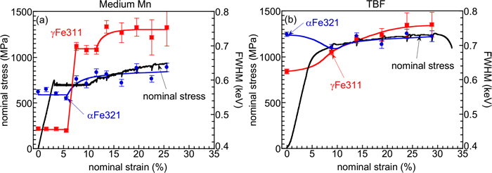
Fig. 11. Variations in full width at half maximum (FWHM) of αFe321 and γFe311 as a function of nominal strain and corresponding nominal stress–strain curve in (a) M–Mn and (b) TBF steels. (Online version in color.)

Fig. 12. Variations in volume fraction of retained austenite (fγ) as a function of nominal strain and corresponding nominal stress–strain curve in (a) medium Mn and (b) TBF steels. (Online version in color.)
4. Discussion
The distributions of the elastic strain, FWHM, and volume fraction of the retained austenite were homogeneous in the parallel part of the TBF steel specimen until necking occurred. In the Lüders elongation region of the medium Mn steel, however, the elastic strain, FMHW, and retained γ volume fraction distributions were clearly different between the non-Lüders deformed and Lüders deformed positions in the parallel part of the tensile specimen, whereas those values were uniform throughout the parallel part and varied with the nominal strain. Therefore, the martensitic transformation behaviors of retained austenite during Lüders deformation and work hardening are presumably affected by different factors. In the following section, the martensitic transformation of retained austenite and work hardening behaviors in the medium Mn steel will be discussed, considering the stress (elastic strain) and plastic strain (FWHM) partitioning between the ferrite and austenite phases. Here, the TBF steel might possess dynamic recovery during plastic deformation, resulting in a decrease in the FWHM because the initial dislocation density of the ferrite phase (bainitic ferrite) before the tensile test was high. Therefore, it may be difficult to discuss the FWHM partitioning behavior of ferrite and austenite phases because the dynamic recovery possibly affects the change in the FWHM of ferite phase during the plastic deformation regime after yielding. Thus, in the present study, the change in the plastic strain distribution behavior of the TBF steel is not discussed.
4.1. Martensitic Transformation Behavior and Stress and Plastic Strain Partitioning Behaviors during Lüders Elongation Regime
In the Lüders elongation regime of the medium Mn steel, the elastic and plastic strains and volume fraction of the retained austenite varied significantly between the regions before and after Lüders deformation, showing macroscopically inhomogeneous distributions across the tensile specimen. Previous research31) utilizing the visualization of the Lüders band propagation behavior at the parallel part of the tensile specimen using tensile tests with digital image correlation (DIC) revealed that plastic deformation occurred only at the Lüders front (the strain rate at the Lüders front was large) and no change in plastic strain was observed in the pre-Lüders deformed and Lüders-deformed regions. In addition, it has been reported that X-ray diffraction measurements revealed that martensitic transformation did not occur in the Lüders elongation regime before and after Lüders deformation, although a large amount of retained austenite transformed into martensite during Lüders deformation.17,21) In the present study, it has been revealed that the FWHM corresponding to the plastic strain of both ferrite and austenite (Figs. 7, 8) and the volume fraction of retained austenite (Fig. 9) were individually constant across the pre-Lüders deformed and Lüders deformed regions. In addition, Koyama et al.18) investigated the microscopic plastic strain generation behaviors and martensitic transformation behavior of retained austenite using the in-situ observation and EBSD analysis of the microstructure of medium Mn steel during tensile test in SEM. They showed that the plastic deformation at the Lüders front initiated on the edge of one side of the parallel part of the tensile specimen and propagated preferentially through the retained austenite toward the other side edge. During the plastic deformation, the amount of plastic deformation of ferrite was apparently small in comparison with that of austenite. Furthermore, there were two types of retained austenite that coexisted during the plastic deformation process. One of them exhibited significant martensitic transformation and the other showed dislocation slip without transformation. In the present study, because the increase in the FWHM of austenite was remarkable compared to that of ferrite (Figs. 7, 8, 11), it is suggested that the retained austenite that did not transform to martensite underwent significant plastic deformation. In addition, the considerable decrease in the volume fraction of retained austenite (Figs. 9, 12) suggests that the transformation of retained austenite occurred simultaneously. These findings are consistent with the results reported by Koyama et al.18) Austenite of the medium Mn steel exhibited a higher elastic strain than ferrite at the pre-Lüders deformed points in the Lüders elongation regime (Fig. 10). According to the microscopic analysis by Koyama et al.,18,19) the deformation discontinuously initiated in the width direction of the specimen, and the Lüders front was formed owing to the propagation of the Lüders deformation in the width direction. Consequently, it is considered that the retained austenite located at the Lüders front undergoes martensitic transformation when the stress applied to the retained austenite reaches critical stress due to the tensile stress and stress concentration caused by inhomogeneous deformation and stress triaxiality. Therefore, it was assumed that a large amount of retained austenite transformed into martensite, and in contrast, the retained austenite, which did not transform into martensite owing to its high stability, was subjected to significant plastic strain, and its FWHM was remarkably increased. In addition, since the transformation from retained austenite to α′ martensite is accompanied by volume expansion,32) it is predicted that the effect of stress relaxation became large at the Lüders front due to the martensitic transformation of a large amount of retained austenite and that the stress increase is suppressed in each phase. From the above consideration, it is assumed that, in the Lüders deformation regime of the medium Mn steel in the present study, the increase in the stress (i.e. elastic strain) of ferrite located around transformed martensite at the Lüders front was small because of a large amount of martensitic transformation of retained austenite in addition to the slip deformation of retained austenite. It is also assumed that the average stress of retained austenite was decreased because most of the retained austenite with high applied stress was transformed into martensite.
4.2. Martensitic Transformation Behavior of Retained Austenite and Stress and Plastic Strain Partitioning Behaviors at Work Hardening Regime
During the work hardening of the medium Mn steel, the distributions of the elastic and plastic strains and the volume fraction of the retained austenite at the parallel part of the tensile specimen were homogeneous, suggesting homogeneous deformation. The main factors affecting the work hardening of steels that possess deformation-induced martensitic transformation of retained austenite are the increased dislocation density in the matrix by plastic strain and the generation of the hard phase due to the martensitic transformation of retained austenite.33,34) The increase in the FWHM of ferrite in the work hardening regime was small, suggesting that the contribution of ferrite matrix on work hardening might be relatively small.
A large amount of the retained austenite in the medium Mn steel transformed into martensite and a large plastic strain was thought to be applied to the retained austenite which was stable and untransformed during Lüders deformation because the FWHM of the remaining retained austenite significantly increased during Lüders deformation. The untransformed retained austenite with a high density of dislocations introduced during Lüders deformation possessed a large number of nucleation sites of martensitic transformation, such as intersections of slip bands, and the plastic strain applied further might cause the martensitic transformation of the retained austenite at these nucleation sites.35) It is suggested that the slight increase in the plastic strain induced martensitic transformation at various portions of the parallel part of the tensile specimen of the medium Mn steel in the work hardening regime, despite the low inclement of stress. Probably, a large number of dislocations were introduced to the retained austenite in the Lüders elongation regime, which enhanced the martensitic transformation. During Lüders deformation of the medium Mn steel, since the local plastic strain of the retained austenite at the Lüders front was responsible for the macroscopic plastic strain, the significant plastic strain was introduced to the retained austenite. In the work hardening regime, in contrast, the entire parallel part of the tensile specimen was responsible for the macroscopic plastic strain, and a gradual increase in the FWHM of austenite and a gradual martensitic transformation of the retained austenite was observed (Fig. 12). The elastic strain of martensite formed by deformation-induced transformation from retained austenite increased with increasing plastic deformation in the work hardening regime (Fig. 5) and the FWHM also increased (Fig. 7), suggesting that the transformed martensite mainly shared the increase in stress and plastic strain. Martensite transformed from retained austenite with a high dislocation density also exhibits a high dislocation density in general.36) Therefore, the martensite phase transformed during the work hardening regime has a high dislocation density, showing high average values of FWHM, and the FWHM and elastic strain increased in the work hardening regime of the medium Mn steel. It is also considered as another possible hypothesis that the elastic strain and FWHM increased because of the plastic deformation of the transformed martensite itself as plastic deformation proceeded. However, the authors think it is more plausible that the increases in the elastic strain and FWHM of martensite are attributed to the martensite with a high dislocation density newly transformed from retained austenite already subjected to considerable plastic deformation. In addition, it is considered that dynamic strain aging accompanying serration occurred during the work hardening regime owing to the interaction between the high density of dislocations and solute carbon in the retained austenite. Stress relaxation may occur because of volume expansion during the martensitic transformation of the retained austenite. However, the obvious stress relaxation behavior might not appear because a small amount of retained austenite transformed into martensite, and tensile deformation was continuously applied in the plastic deformation regime accompanied by work hardening.
In the TBF steel, the elastic strain of austenite was high in comparison with that of ferrite (Fig. 10), implying the high stress sharing of austenite at the work hardening regime. The stability of the retained austenite was high, and the retained austenite exhibited high resistance to slip deformation compared with that of medium Mn steel because the carbon concentration in the retained austenite was high. Thus, martensitic transformation of the retained austenite in the TBF steel requires high stress. The stress at the parallel part of the tensile specimen in the TBF steel was homogeneously distributed, and the retained austenite gradually transformed into martensite during plastic deformation as well as that in the work hardening regime in the medium Mn steel. Therefore, the plastic deformation of the TBF steel was accompanied by a decrease in stress relaxation, and the stress of the retained austenite remained high.
5. Conclusions
The high-energy synchrotron X-ray diffraction experiments during tensile deformation were carried out to clarify the plastic strain distribution and stress partitioning behaviors of ferrite, austenite, and martensite at the parallel part of the tensile specimen during Lüders elongation and the plastic deformation with work hardening regimes in the medium Mn and TBF steels. Furthermore, the retained austenite distribution and martensitic transformation behavior of retained austenite were separately analyzed. The results are summarized as follows:
(1) The elastic strain, full width at half maximum (FWHM), and volume fraction of the retained austenite changed remarkably during Lüders deformation in the medium Mn steel, resulting in the heterogeneous deformation. In contrast, the distribution of elastic strain, FWHM, and volume fraction of retained austenite in the plastic deformation regime with work hardening were homogeneous in the parallel part of the tensile specimen, that is, the medium Mn and TBF steels exhibited homogeneous deformation after Lüders deformation.
(2) A large amount of retained austenite showed martensitic transformation during Lüders deformation in medium Mn steel. This can be attributed to the high stress in the retained austenite and the preferential plastic deformation of the retained austenite at the Lüders front. Moreover, the average stress of the retained austenite decreased because stress relaxation occurred owing to the martensitic transformation of a large amount of retained austenite at the Lüders front and the rapid disappearance of retained austenite sharing high stress.
(3) The martensitic transformation in both the medium Mn and TBF steels during the plastic deformation regime with work hardening occurred gradually compared with that during the Lüders deformation regime. The martensitic transformation in the work hardening regime might have been induced by high-density dislocations introduced during Lüders deformation and newly introduced dislocations during plastic deformation. In addition, the occurrence of the martensitic transformation of retained austenite in TBF steel might be attributed to the application of high stress to retained austenite with a high carbon concentration.
(4) In the work hardening regime, the medium Mn steel showed less martensitic transformation of the retained austenite per unit plastic strain, resulting in less stress relaxation and the stress and plastic strain increased slightly.
Acknowledgment
The medium Mn steel sheet used in this study was provided by the research project “Heterogeneous Deformation Microstructure and Related Mechanical Properties”, Division of Microstructure and Properties of Materials, The Iron and Steel Institution of Japan. This study was supported by the QST Advanced Characterization Nanotechnology Platform under the remit of the Nanotechnology Platform of the Ministry of Education, Culture, Sports, Science and Technology (MEXT), Japan (Proposal Nos. A-18-QS-0034, A-20-QS-0016 and A-21-QS-0033). The synchrotron radiation experiments were performed using the QST experimental station at QST (JAEA) beamline BL14B1, SPring-8, with approval from the Japan Synchrotron Radiation Research Institute (JASRI) (Proposal Nos. 2018B3681, 2020A3681 and 2021B3681).
References
- 1) K. Hikida, T. Nishibata, H. Kikuchi, T. Suzuki and N. Nakayama: Materia Jpn., 52 (2013), 68 (in Japanese). https://doi.org/10.2320/materia.52.68
- 2) Y. Yoshito and K. Kita: Aisin Tech. Rev., 24 (2020), 32 (in Japanese).
- 3) J. Han, J.-H. Nam and Y.-K. Lee: Acta Mater., 113 (2016), 1. https://doi.org/10.1016/j.actamat.2016.04.038
- 4) Q. Y. Liu, Y. Yan, J. P. Xu, S. Q. Yang, J. X. Li, Y. J. Su and L. J. Qiao: Journal of Materials Engineering and Performance, 29 (2020), 1929. https://doi.org/10.1007/s11665-020-04706-z
- 5) H. Natsumeda, A. Kitahara and S. Hashimoto: Tetsu-to-Hagané, 104 (2018), 274 (in Japanese). https://doi.org/10.2355/tetsutohagane.TETSU-2017-069
- 6) K. Sugimoto, M. Tsunezawa, T. Hojo and S. Ikeda: ISIJ Int., 44 (2004), 1608. https://doi.org/10.2355/isijinternational.44.1608
- 7) F. G. Caballero, C. Garcíá-Mateo, J. Chao, M. J. Santofimia, C. Capdevila and C. G. d. Andrés: ISIJ Int., 48 (2008), 1256. https://doi.org/10.2355/isijinternational.48.1256
- 8) Y. Zhou, T. Hojo, M. Koyama, S. Ajito and E. Akiyama: Mater. Sci. Eng. A, 842 (2022), 143070. https://doi.org/10.1016/j.msea.2022.143070
- 9) Y. Zhou, T. Hojo, M. Koyama and E. Akiyama: Mater. Sci. Eng. A, 819 (2021), 141479. https://doi.org/10.1016/j.msea.2021.141479
- 10) J. Wang, W. Hui, Z. Xie, Z. Wang, Y. Zhang and X. Zhao: Int. J. Hydrog. Energy, 45 (2020), 22080. https://doi.org/10.1016/j.ijhydene.2020.05.239
- 11) X. G. Wang, C. H. Liu, B. B. He, C. Jiang and M. X. Huang: Mater. Sci. Eng. A, 761 (2019), 138050. https://doi.org/10.1016/j.msea.2019.138050
- 12) Y. Zhou, M. Koyama, T. Hojo, S. Ajito and E. Akiyama: Metall. Mater. Trans. A, 54 (2022), 153. https://doi.org/10.1007/s11661-022-06855-3
- 13) M. Zhang, H. Chen, Y. Wang, S. Wang, R. Li, S. Li and Y.-D. Wang: Journal of Materials Science & Technology, 35 (2019), 1779. https://doi.org/10.1016/j.jmst.2019.04.007
- 14) W. Yin, F. Briffod, H. Hu, K. Yamazaki, T. Shiraiwa and M. Enoki: Scripta Materialia, 229 (2023), 115386. https://doi.org/10.1016/j.scriptamat.2023.115386
- 15) A. Dutta, D. Ponge, S. Sandlöbes and D. Raabe: Materialia, 5 (2019), 100252. https://doi.org/10.1016/j.mtla.2019.100252
- 16) T. Hojo, M. Koyama, B. Kumai, Y. Shibayama, A. Shiro, T. Shobu, H. Saitoh, S. Ajito and E. Akiyama: Scripta Materialia, 210 (2022), 114463. https://doi.org/10.1016/j.scriptamat.2021.114463
- 17) M. Zhang, L. Li, J. Ding, Q. Wu, Y.-D. Wang, J. Almer, F. Guo and Y. Ren: Acta Mater., 141 (2017), 294. https://doi.org/10.1016/j.actamat.2017.09.030
- 18) M. Koyama, T. Yamashita, S. Morooka, T. Sawaguchi, Z. Yang, T. Hojo, T. Kawasaki and S. Harjo: ISIJ Int., 62 (2022), 2036. https://doi.org/10.2355/isijinternational.ISIJINT-2021-510
- 19) M. Koyama, T. Yamashita, S. Morooka, Z. Yang, R. S. Varanasi, T. Hojo, T. Kawasaki and S. Harjo: ISIJ Int., 62 (2022), 2043. https://doi.org/10.2355/isijinternational.ISIJINT-2022-098
- 20) X. G. Wang, L. Wang and M. X. Huang: Acta Mater., 124 (2017), 17. https://doi.org/10.1016/j.actamat.2016.10.069
- 21) J. Han, S.-J. Lee, J.-G. Jung and Y.-K. Lee: Acta Mater., 78 (2014), 369. https://doi.org/10.1016/j.actamat.2014.07.005
- 22) L. Morales-Rivas, C. Garcia-Mateo, T. Sourmail, M. Kuntz, R. Rementeria and F. Caballero: Metals, 6 (2016), 302. https://doi.org/10.3390/met6120302
- 23) K. Hausmann, D. Krizan, K. Spiradek-Hahn, A. Pichler and E. Werner: Mater. Sci. Eng. A, 588 (2013), 142. https://doi.org/10.1016/j.msea.2013.08.023
- 24) T. Matsuno, T. Hojo, I. Watanabe, A. Shiro, T. Shobu and K. Kajiwara: Science and Technology of Advanced Materials: Methods, 1 (2021), 56. https://doi.org/10.1080/27660400.2021.1922207
- 25) Z. C. Li, H. Ding, R. D. K. Misra and Z. H. Cai: Mater. Sci. Eng. A, 679 (2017), 230. https://doi.org/10.1016/j.msea.2016.10.042
- 26) R. S. Varanasi, S. Zaefferer, B. Sun and D. Ponge: Mater. Sci. Eng. A, 824 (2021), 141816. https://doi.org/10.1016/j.msea.2021.141816
- 27) B. Fu, W. Y. Yang, L. F. Li and Z. Q. Sun: Mater. Sci. Eng. A, 603 (2014), 134. https://doi.org/10.1016/j.msea.2014.02.082
- 28) N. Tsuchida, T. Tanaka and Y. Toji: Tetsu-to-Hagané, 105 (2019), 918 (in Japanese). https://doi.org/10.2355/tetsutohagane.TETSU-2019-014
- 29) N. Tsuchida, T. Tanaka and Y. Toji: ISIJ Int., 61 (2021), 564. https://doi.org/10.2355/isijinternational.ISIJINT-2020-378
- 30) K. Tanaka and Y. Akiba: J. Soc. Mat. Sci., Japan, 52 (2003), 1435. https://doi.org/10.2472/jsms.52.1435
- 31) B. Sun, N. Vanderesse, F. Fazeli, C. Scott, J. Chen, P. Bocher, M. Jahazi and S. Yue: Scripta Materialia, 133 (2017), 9. https://doi.org/10.1016/j.scriptamat.2017.01.022
- 32) S. Lee, S.-J. Lee and B. C. De Cooman: Acta Mater., 59 (2011), 7546. https://doi.org/10.1016/j.actamat.2011.08.030
- 33) J. Shi, X. Sun, M. Wang, W. Hui, H. Dong and W. Cao: Scripta Materialia, 63 (2010), 815. https://doi.org/10.1016/j.scriptamat.2010.06.023
- 34) J. Chiang, B. Lawrence, J. D. Boyd and A. K. Pilkey: Mater. Sci. Eng. A, 528 (2011), 4516. https://doi.org/10.1016/j.msea.2011.02.032
- 35) J. L. Wang, M. H. Huang, X. H. Xi, C. C. Wang and W. Xu: Materials Characterization, 163 (2020), 110234. https://doi.org/10.1016/j.matchar.2020.110234
- 36) T. Maki, T. Furuhara, N. Tsuji, S. Morito, G. Miyamoto and A. Shibata: Tetsu-to-Hagané, 100 (2014), 1062 (in Japanese). https://doi.org/10.2355/tetsutohagane.100.1062

