Abstract
Diesel nozzle tips with tapered spray holes (inwardly larger) were produced using newly developed powder metallurgy (P/M) processing. Spray holes were formed by resin cores made by a three-dimensional printer. A 2.6 μm steel powder (SCM415) was prepared as a slurry, and was compacted using a high-speed centrifugal compaction process into the resin mold with the core. The mold, core, and binder in the green compacts were eliminated by thermal decomposition, and the compacts were sintered by successive heating. Nozzle tips with three tapered holes were made in the sintered products without cracking or breakage. Although some problems exist in the remaining pores, large outlet holes (about 200 μm) and a carbon residue, the holes can be used for spray examination.
1 Introduction
Research on diesel engines has focused on the simultaneous reduction in emissions of harmful substances such as NOx gases and particulate materials1). The formation of these emissions is related strongly to the diesel combustion system that is, to the direct spray of fuel in the cylinder and natural ignition by adiabatic heating. The solution to this problem is related to spray quality. Effective fuel spray is achieved from tiny and strong, long-distance-penetrating spray2), which provides uniform and completely vaporized fuel in the cylinder at the time of combustion. Significant effort has been made in this regard, mainly by improving high-pressure common rail systems. However, total reductions in emission are still insufficient and spray conditions such as multi-time sprays and back pressure elevation have been managed, but not improved3,4). An improvement in spray hole shape is also of prime importance. Obtaining smaller, multiple, grope-holed, and tapered holes may lead significant advances in this area. The aim of our work was to establish a method to manufacture micro, multiple, and tapered-holed nozzle tips for diesel engines using the recently developed P/M process, since any conventional processing methods are difficult to adopt to produce such holes. We chose the high-speed centrifugal compaction process (HCP) for powder compaction. The HCP is a slurry-based process; powder in the slurry is deposited at the bottom of the mold by centrifugal force. By HCP, small powders of a few microns or less can be refilled densely into complexly shaped mold cavities. In HCP, plastic core can also be placed and be buried in powder sediment without collapsing, because the core is supported by quasi-hydraulic pressure generated by centrifugal force during the process. The core that will form the spray holes is prepared by ultraviolet (UV)-resin three-dimensional (3D) printer. The core is eliminated by thermal decomposition during the heating process after the HCP, and then the compact is sintered by further heating5–7).
2 Experimental Procedure
2.1 Nozzle manufacture
Fig. 1 shows the nozzle manufacturing process. A resin compacting mold is assembled by stacking ring-shaped parts, within which a resin core was set for spray hole formation (a). Steel powder is prepared as a non-aqueous slurry and is poured into the mold cavity (b), is set in the centrifuge and is compacted by the HCP (c). After compaction, the resin in the slurry is cured and the top half of the mold is removed (d). A heating process follows. At low temperature, the resin mold and core are decomposed thermally. Mechanical mold release and removal of the core can be avoided (e). The compact is heated to high temperature for sintering (f).
2.2 Slurry conditions
Water-atomized steel powder (SCM415, average grain size of 2.6 μm, Epson Atmix Co., Japan) was used. The dispersing medium was styrene monomer (C6H5CH:CH2). Some dispersing agent and binder resin (with curing agent and hardening accelerator) were also added. Slurry was prepared by manual agitation. Table 1 shows the slurry composition.
Table 1
Slurry composition.
| Component |
Description |
Composition [g] |
| Powder |
SCM415 |
EPSON ATMIX Co., Ltd. |
70 |
| Dispersing medium |
Styrene monomer |
KANTO CHEMICAL Co., Inc. |
10 |
| Binder |
Urethane acrylate type |
Japan U-Pica Co., Ltd. |
10 |
| Dispersing agent |
Poly-oxyethylene type |
Kao Co., Ltd. |
2.8 |
| Accelerant of binder |
PR-N |
Japan U-Pica Co., Ltd. |
0.05 |
| Catalyst |
Permek N |
Japan U-Pica Co., Ltd. |
0.3 |
Polyethylene (PE) and polyoxymethylene (POM) resins were selected as mold materials. PE is the most basic, simple molecular resin with a relatively low softening temperature. POM shows, by differential thermal analysis (DTA) observation, a good thermal decomposing performance at low temperature without leaving a carbon residue. Both resins showed a satisfactory machinability using a conventional lathe. Relatively simple, ring-shaped parts were machined and assembled by stacking the parts from the bottom upwards, and by setting a core in the designated place.
2.4 Cores
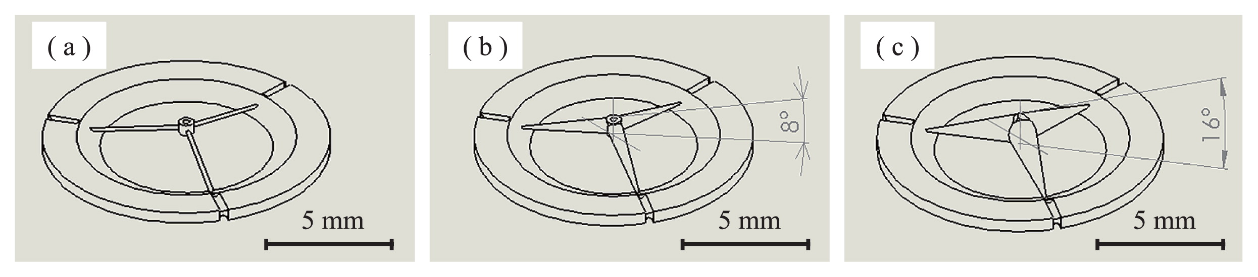
Three core types were prepared (Fig. 2); one with straight holes (a) and the others with low-tapered holes at 8° (b), and high-tapered holes at 16° (c), all of which were used to form tapered spray holes.
2.5 Compaction
Prepared slurry was poured into a mold and rotated by high-speed centrifuge (Hitachi Koki Co. GR22G, rotor radius of 120 mm) at 7,000 rpm for 40 min, at 253 K. After the HCP, the entire mold was placed in a dry oven at 313 K for one day to achieve the strength required for handling by curing binder resin in the green compact.
2.6 Heating process
Fig. 3 and Table 2 show the heating program and conditions, respectively. The furnace was kept at a high vacuum of 1.1 × 10⁻³ Pa throughout the process. First, it was heated slowly from 473 to 773 K at 1.25 K/h to remove the mold, core, and binder resin successively by thermal decomposition. Then, it was heated to 1473 K and sintered at this temperature for 3.6 ks.
Table 2
Heating condition.
| Temperature [K] |
Heating rate [K/h] |
Elapsed time [h] |
Atmosphere |
| Room temperatuer-453 |
— |
1 |
Vacuum 1.13 × 10⁻³ [Pa] |
| 453–473 |
20 |
1 |
| 473–773 |
1.25 |
240 |
| 773–1373~1473 |
200 |
3–3.5 |
| 1273~1473 |
— |
1 |
The quality of the semi-finished products (such as the green bodies before and after mold-release) and the finished sintered products were evaluated visually, by optical microscopy and by scanning electron microscopy (SEM).
3 Results and discussion
3.1 Mold material selection
The thermal decomposition behavior of the two PE and POM resins were compared. Figs. 4 and 5 show the DTA and thermogravimentry (TG) curves of the resins. A characteristic endothermic peak in the DTA curve of PE (Fig. 4) at about 630 K indicates where the thermal decomposition of PE commences. The TG curve reduction at approximately the same temperature also supports the validity of this observation. For the POM, the DTA dip commences only at about 540 K. The POM has a lower thermal decomposition temperature than PE. Although the PE appears to have a simpler composition, it requires a higher temperature for thermal decomposition. Figs. 6 and 7 show the DTA and TG curves of the binder resin and the UV-hardening acrylic resin used in the 3D printer, respectively. Although the DTA curves are slightly ambiguous, we can determine the thermal decomposition temperatures of the binders (at 500 K), and of the UV-hardened acrylic (at 570 K). In total, the order of thermal decomposition for constant heating is, i) binder resin, ii) POM mold, iii) acrylic resin core, and iv) PE mold. There is distinctive difference in the decomposition order of the two molds, which affects the process significantly.
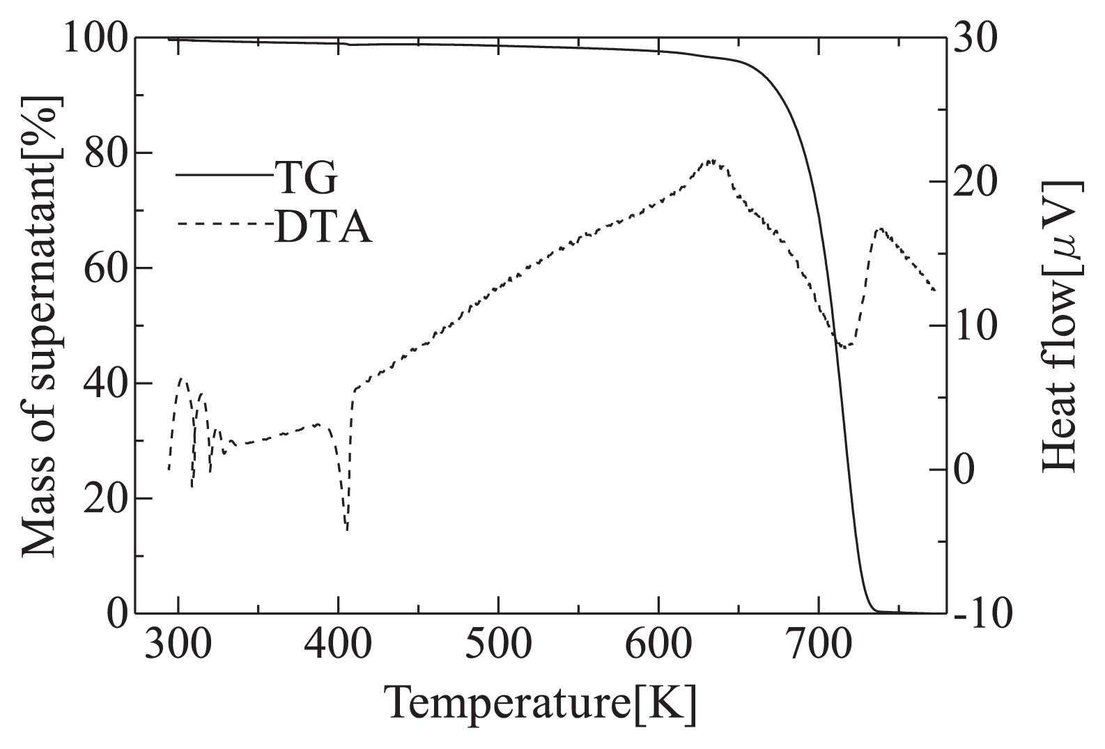
Fig. 2 shows the core appearance. The cores can be made successfully by 3D printer. Each core consists of a center piece, three arms which will become spray holes, and an outer fringe. The center piece and fringe support the arms; that is, the arms are key components in spray hole formation. The outer ends of the arms are of primary importance where they connect to the fringe, since they determine the spray hole diameter. However, the minimum obtainable sizes at the outer end of the arms are about 200 μm, which is twice or triple the expected nozzle size, because of performance limitations of the printer.
3.3 Compaction by HCP
Fig. 8 (a) shows a sample cross section after the HCP (after the binder resin cured). The powder is conveyed throughout the mold cavity. No cracks or breakage were observed. The dark fringe above the bottom end of the compact is the fringe of the core. The powder is refilled around the arms of the core. Fig. 8 (b) shows an overview of the compact after cutting and drilling to form the inner shape. Sufficient strength of the green compact (with binder resin compound) allows it to be cut and drilled without cracking.
3.4 Mold and core-release and de-binding
The sample appearances after thermal decomposition of the resins (heated to 723 K) are shown in Fig. 9. For two samples, only the mold material differed; sample (a) was made with the POM mold and (b) was made with PE. Only the POM sample was de-molded and de-bound successfully, whereas the sample with PE contained a considerable amount of carbon residue. This residue was not eliminated at elevated temperature. The poor thermal decomposition property of PE (see Fig. 4) may make full elimination of the resins more difficult, at least compared with the POM sample. The POM sample requires extensive time (240 h, see Fig. 3 and Table 2) for thermal decomposition, since cracks were introduced by more rapid heating. Cracking may be caused by pressure of the rapidly emerged decomposed gases. Fig. 10 shows that the appearance of the UV-resin cores during thermal decomposition at each temperature, which indicates that the UV-resins were eliminated completely up to 773 K.
3.5 Sintering
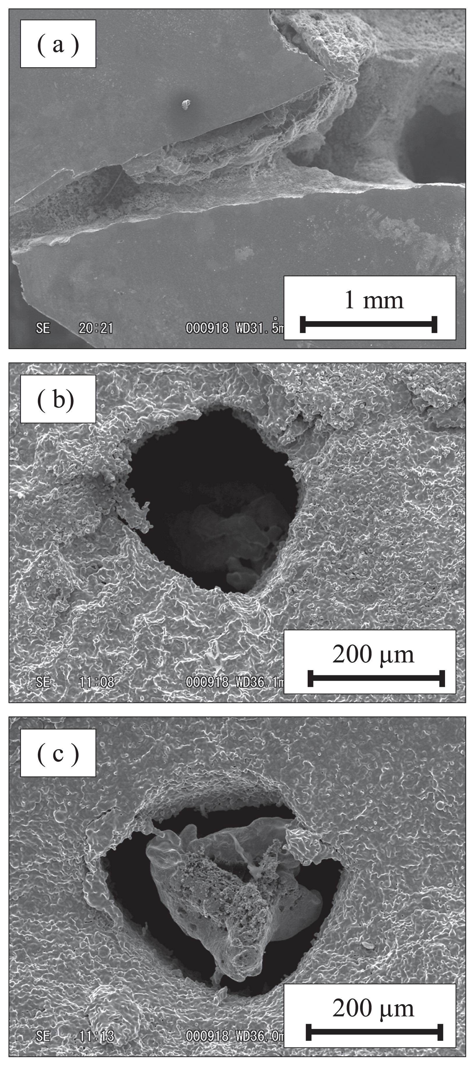
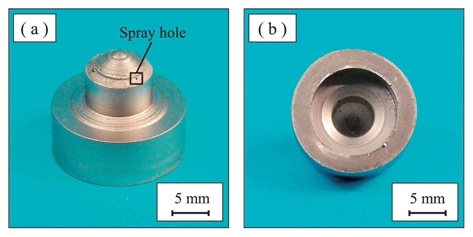
The sintered nozzle appearance is shown in Fig. 11. Every sample can be sintered without introducing cracks and breakage, at least after controlling several process conditions. The sintered nozzle cross sections are summarized in Fig. 12. A dense and uniform microstructure is obtained throughout the nozzle, namely, the microstructures at the bottom, middle and top part of the sample are almost the same. This result indicates that the nozzle produced by the HCP process may have uniform strength throughout the sample, although some remaining pores must be eliminated to prevent cracking and to improve creep resistance in actual use. Fig. 13 shows enlarged SEM images around the spray holes. A spray hole with tapered shape toward the nozzle outlet is formed on the product surface. No cracks or breakage exist at or around the holes. However, several problems are revealed from the observation, one of which is the hole size. As shown in the core preparation section, the minimum possible core diameter was about 200 μm. Therefore, the finished spray holes also become that approximate size. Moreover, the hole shape is not spherical, possibly because of limitations in 3D-printer performance (minimum process step of 50 μm). Limitations in 3D-printer performance also affect the surface roughness of spray holes, in which stepwise shapes are “imprinted” from the surface profile of the 3D-printed core. Another problem to highlight includes the fact that some residues of improperly decomposed acrylic cores remain in the spray holes. A further improvement in process conditions, especially in mold and core release, is expected. Although a number of remaining problems exist as mentioned above, a basic procedure for P/M diesel nozzle tip production was established in this study. The performance of the tapered spray holes will be evaluated in a successive report.
4 Conclusions
Diesel nozzle tips with tapered spray holes (inwardly larger) were produced using newly developed P/M processing. Spray holes were formed by resin cores made by 3D printer. A steel powder of 2.6 μm (SCM415) was prepared as a slurry, and was compacted by the HCP into a resin mold with core. The mold, core, and binder in the green compacts were eliminated by thermal decomposition and the compacts were sintered in successive heating. The results obtained in this study are as follows.
-
1)
Acrylic cores with tapered spray holes can be made using the UV-hardening 3D printer. The minimum core diameter is, however, is much larger (about 200 μm) than required for clean diesel engines.
-
2)
POM resin stack molds that contain cores can be used for the HCP without leaking or other problems. Dense and homogeneously compacted green compacts, in which the cores are buried, are obtained. No cracks or breakage were observed.
-
3)
The POM resin molds were eliminated completely by thermal decomposition in the vacuum furnace. The binder resin in the green compacts was also eliminated. However, the decomposition process requires a long time of 240 h.
-
4)
After mold-core release and de-binding, the compact can be sintered at about 1473 K in vacuum. Dense and homogeneous microstructures were obtained throughout the products, although tiny pores were still included.
-
5)
Nozzle tips with tapered spray holes were produced using the abovementioned process. Although a number of problems remain in terms of the spray hole quality, the holes are actually formed in sintered products without cracking or surrounding breakage.
References
- 1) T. Suzuki: “Diesel engine and automobile”, Miki press, (1997) 156–190.
- 2) T. Tanaka, Y. Sato, O. Horikoshi, T. Yoda, H. Shibata: “Research Concerning Injection Nozzle Shape for Direct-Injection Diesel Engine Using Common Rail Injection System”, Denso technical review, 8 (2003) 29–38.
- 3) K. Nishida: “Diesel Spray and Combustion Injected by Micro-Hole Nozzle under Ultra-High Injection Pressure”, Nagare, 30 (2012) 345–350.
- 4) N. Tamaki, M. Shimizu, M. Arai, H. Hiroyasu: “Enhanced Atomization of a Liquid Jet and Control of its Spray Dispersion”, Biryuka, 8 (1999) 483–489.
- 5) H. Y. Suzuki, R. Matsuo, K. Matsuzaki: “Compaction of Complex Shape Parts with Core by High-speed Centrifugal Compaction Process (Vol. 1)—Development of Slip which Enables to Provide Strong Green Compacts”, J. Jpn. Soc. Powder Powder Metallurgy, 54 (2007) 713–721.
- 6) H. Y. Suzuki, M. Nagai, K. Matsuzaki, M. Arai, Y. Shimoitani: “Compaction of Complex Shape Parts with Core by High-speed Centrifugal Compaction Process (Part 2)— Fabrication of Tiny and Multiple Holed Nozzle for Diesel Engine—”, J. Jpn. Soc. Powder Powder Metallurgy, 55 (2008) 703–708.
- 7) H. Y. Suzuki, Y. Nozaki: “Fabrication of Clean Diesel Nozzle Tips by PM Process using High-Speed Centrifugal Compaction and 3D printer”, JSME annual meeting, 14 (2014).