Abstract
We examined an alkaline ring complex in the Eastern Desert of Egypt, Wadi Dib ring complex (WDRC), to understand formation mechanisms of the intimately related ring structure and chemical diversity. The WDRC consists of multiple circular rings of the oldest volcanic units, the middle-stage plutonic unit, and the youngest dike unit, and these units show overlapping whole-rock major element compositions. The compositional variation of the volcanic and plutonic units can be accounted for by a stepwise fractional crystallization starting with a trachytic magma without significant magma replenishment or crustal contamination. From the margin to the center and oldest to youngest, the plutonic unit consists of an outer ring (syenite), inner rings 1 (quartz-bearing syenite) and 2 (quartz syenite), and a granitic core (syenogranite). The whole-rock chemical composition of the plutonic unit is progressively more fractionated inwards from the outer ring to the granitic core through the inner rings. Syenites from the innermost outer ring show high degree of deformation, which gradually decreases outwards in the outer ring and abruptly decreases inwards in the outermost inner ring 1. The deformed syenites show microstructures suggesting reactive melt transportation. The country rocks neighboring the ring complex and equivalent blocks present in the periphery of the outer ring, the overlying volcanic unit and equivalent blocks present in the inner rings all show microstructures indicative of pyrometamorphism. Spatial variations in the microstructures in the plutonic unit indicate an increase in cooling rate from the outer ring to the granitic core and thus with time. These geological, chemical, and microstructural features of the WDRC suggest that the ring complex represents an evolving roof zone of a subvolcanic magma body located at a depth of a few km. Intimate coupling of growing roof and sidewall mushy boundary layers and later collapse of the roof boundary layer with occasional involvement of the overlying volcanic piles induced segregation of interstitial fractionated melt from the wall boundary layer to the collapse space driven by a pressure gradient induced by the collapse. The ascended fractionated melt started to crystallize to form a roof boundary layer of the next generation by increasing cooling efficiency, which thickened until the next collapse on a smaller horizontal scale inducing melt segregation from the wall boundary layer towards the roof zone. Repetition of the sequence with shallowing and decreasing the horizontal scale produced the ring structure and chemical diversity of the WDRC.
INTRODUCTION
Intrusive bodies exposed on the surface have been regarded as ancient magma chambers and expected to provide opportunities to directly observe materials that filled them. However, we must pay attention to the essential difference of geophysically observed magma chambers and intrusive bodies. Most intrusions do not represent active in-situ magma bodies but finally solidified entities resulting from often complex cooling histories involving magma supply from the underlying magma body experiencing both tapping and fractionation. If these complexities are carefully taken into consideration, intrusive bodies have the potential to provide more accurate understanding of magma chamber processes. Our study applies this concept to one of the alkaline ring complexes in the Eastern Desert of Egypt, which show a concentric distribution of diverse lithologies of plutonic and even volcanic rocks.
The Arabian-Nubian Shield (ANS) has a crust with a thickness 25-45 km (Al-Damegh et al., 2005; Hansen et al., 2007; Hosny and Nyblade, 2016; Mooney et al., 1985; Sobh et al., 2019; Tang et al., 2016; Yao et al., 2017), which is underlain by lithospheric mantle with a thickness of 50-120 km (Stern and Johnson, 2010). The current heat flow in the Arabian-Nubian shield is 35-70 mWm−2 (Morgan et al., 1985; Rolandone et al., 2013). In the ANS of northeastern Africa (Egypt, Sudan, and Ethiopia), more than 130 ring complexes have been emplaced in the period extending from the final stage of the Pan-African orogeny to the Red Sea rift opening (650-30 Ma; Vail, 1989). The distribution of alkaline rocks shows a high concentration in the Eastern Desert ranging from northern Sudan to southern Egypt.
The Eastern Desert of Egypt is divided into three domains based on lithologic associations with bounding shear zones: North Eastern Desert, Central Eastern Desert, and South Eastern Desert (Stern and Hedge, 1985). In the Eastern Desert, about 15 alkaline ring complexes are distributed in the Proterozoic rocks of gneisses, metasediments, island arc volcanics, and granitoids (El Ramly and Hussein, 1985; Fig. 1). These ring complexes show diversities in chemical composition, lithology, and formation age (Table 1 and Supplementary Table S1; Tables S1-S8 are available online from https://doi.org/10.2465/jmps.220801). A wide variety of rock types, ranging from basic to acidic and from nepheline-bearing (undersaturated) to quartz-bearing rocks (oversaturated), occur in these complexes (e.g., Akaad and El Ramly, 1962; El Ramly et al., 1969, 1971; El Ramly and Hussein, 1982, 1985). Their formation ages range from Late Proterozoic (∼ 610 Ma) to late Cretaceous (∼ 90 Ma) with noticeable peaks of activity at ∼ 100 Ma occurring in the southern part and at ∼ 600 Ma occurring in the North Eastern Desert (Table 1 and Fig. 2a). El Ramly and Hussein (1985) classified the complexes into four types based on degrees of lithological diversity, silica saturation, and development of ring structure (Table S1). As pointed out by de Gruyter and Vogel (1981), rocks having whole-rock compositions undersaturated in silica or high in alkalis, which are characterized by the association of nepheline syenite, appears in ages younger than ∼ 150 Ma (Fig. 2b and Table S1).
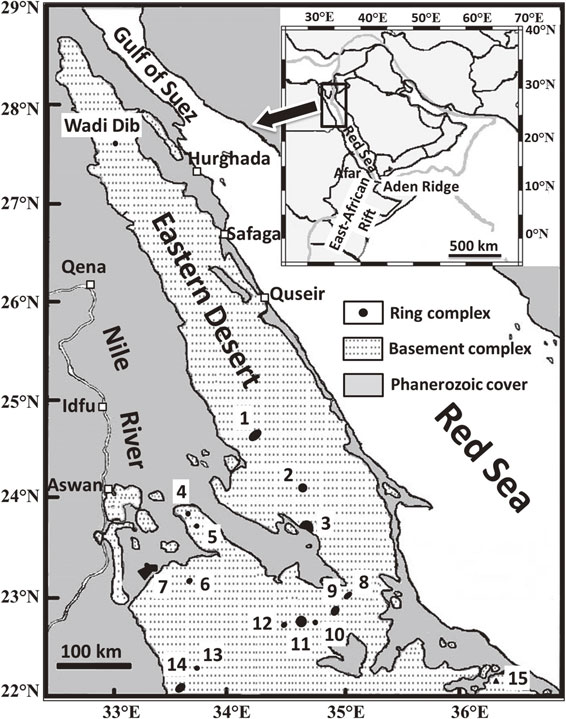
Table 1. Summary of age, morphology, and size of ring complexes in the Eastern Desert of Egypt
| Ring Complexes |
Locations |
Age
(Ma) |
References
for ages |
2D/3D Morphology |
Size
(km) |
Extrusive
area
(%) |
Wadi deposits
distribution |
Altitude
lowest
(m) |
Altitude
highest
(m) |
Exposure
height
(m) |
Height/
Size |
| Latitude |
Longitude |
| Abu Khruq |
24° 38′ 53′′ |
34° 16′ 18′′ |
89.5*, 89†, 89.9§ |
(1), (2), (3) |
Well-defined ring |
7.4 |
20.3 |
IRW |
500 |
874 |
374 |
0.051 |
| Gabal El Kahfa |
24° 08′ 19′′ |
34° 38′ 58′′ |
91*, 92†, 81† |
(1), (13), (4) |
Well-defined ring |
4.1 |
0.3 |
IRW |
500 |
1018 |
518 |
0.126 |
| Gabal Mansouri |
22° 02′ 35′′ |
33° 36′ 18′′ |
132† |
(4) |
Poorly defined ring |
5.3 |
25.1 |
OPRW/ORadW |
400 |
798 |
398 |
0.075 |
Gabal Nigrub
El Fogani (S) |
22° 51′ 36′′ |
34° 56′ 50′′ |
139*, 141†, 133§ |
(1), (13), (3) |
Elliptic mass |
2.4 |
29.2 |
IPRW |
400 |
803 |
403 |
0.168 |
Gabal Nigrub
El Tahtani (N) |
23° 00′ 41′′ |
35° 00′ 50′′ |
140† |
(4) |
Well-defined ring |
6.2 |
19.5 |
ORadW |
510 |
1040 |
530 |
0.085 |
| Gabal Mishbeh |
22° 43′ 03′′ |
34° 41′ 49′′ |
142*, 145†, 148†, 133§ |
(1), (13), (4), (3) |
Poorly defined ring |
6.1 |
7.2 |
ORadW |
550 |
1319 |
769 |
0.126 |
| Gabal Maladob |
22° 44′ 23′′ |
34° 50′ 20′′ |
not dated |
(5) |
Isometric mass |
3 |
0.0 |
ORW |
500 |
1080 |
580 |
0.193 |
| Gabal El Naga |
22° 42′ 05′′ |
34° 28′ 34′′ |
146*, 144† |
(1), (13) |
Well-defined ring |
3.7 |
9.3 |
ORW |
560 |
715 |
155 |
0.042 |
| Gabal El Gezira |
22° 17′ 44′′ |
33° 40′ 36′′ |
229* |
(1) |
Well-defined ring |
3.0 |
39.9 |
IPRW/OIrrW |
300 |
483 |
183 |
0.061 |
| G. Hadayib |
23° 06′ 48′′ |
33° 31′ 33′′ |
295† |
(6) |
Pear-shaped, 2 rings |
4 |
15.9 |
ORadW |
388 |
670 |
282 |
0.071 |
| G. Um Risha |
23° 18′ 37′′ |
33° 17′ 21′′ |
not dated |
(7) |
Elliptic |
8.6 |
16.0 |
IIrrW/ORadW |
360 |
540 |
180 |
0.021 |
| Gabal Tarbtie (South) |
23° 46′ 01′′ |
33° 38′ 28′′ |
not dated |
(14) |
Ring dyke |
4.0 |
10.4 |
IIrrW/OIrrW |
400 |
500 |
100 |
0.025 |
| Gabal Tarbtie (North) |
23° 54′ 32′′ |
33° 36′ 00′′ |
351*, 347* |
(1), (12) |
Ring dyke |
4.6 |
0.6 |
IRW/IIrrW |
380 |
515 |
135 |
0.029 |
| Gabal Zargat Nāam |
23° 45′ 28′′ |
34° 40′ 37′′ |
404*, 402*, 424† |
(1), (12), (13) |
Crescent-shaped |
4.0 |
32.5 |
ICW/OOSd |
510 |
794 |
284 |
0.071 |
| Wadi Dib |
27° 34′ 47′′ |
32° 56′ 48′′ |
553*, 578† |
(1), (8) |
Well-defined ring |
2.2 |
14.5 |
OOSd |
650 |
1018 |
368 |
0.167 |
| Gabal Elba |
22° 11′ 25′′ |
36° 21′ 30′′ |
not dated |
(9) |
Poorly defined ring |
12 |
3.2 |
IPRadW/OOSd |
200 |
1288 |
1088 |
0.091 |
| Katherina |
28° 30′ 34′′ |
33° 57′ 45′′ |
583¶ 595-602¶ |
(10), (11) |
Elliptic |
27.3 |
2.7 |
IPRadW |
740 |
2629 |
1889 |
0.069 |
Geochronology method are: * K-Ar; † Rb-Sr (whole-rock or mineral isochron); ¶ zircon U-Pb; § fission track excluding apatite. References for geochronology: (1) Serencsits et al. (1979, 1981); (2) Lutz et al. (1988); (3) zircon/titanite fission track Omar et al. (1987), where apatite ages are not shown because of its low closure temperature; (4) Hashad and El Reedy (1979); (5) not dated but Mesozoic age is inferred by Abdel-Karim et al. (2021); (6) two point whole rock isochron Ghazaly and Sinha (2002); (7) not dated but Ghazaly and Sinha (2002) assigned it the same age as Hadayib; (8) Frisch (1982), Frisch and Abdel-Rahman (1999); (9) not dated but Abu El-Leil et al. (2017) assumed Post orogenic stage; (10) Katherina pluton by Be’eri-Shlevin et al. (2009); (11) Katherina pluton and ring dike by Moreno et al. (2012); (12) Abdel-Karim and Arva-Sos (2000); (13) Lutz (1979) cited in Figure 1 of El Ramly and Hussein (1985); (14) not dated but Serencsits et al. (1981) refers its geographic link with the Gabal Tarbtie (North) related to the proposed block faulting and fracturing. IRW, inner ring wadi; IPRW, inner partial ring wadi; ICW, central wadi; IPRadW, incomplete radial wadi invaded into the complex; IIrrW, irregular wadi invaded into the complex; ORW, ring wadi surrounding the complex; OPRW, partial ring wadi outside of the complex; ORadW, radial wadi outside of the complex; OIrrW, irregular wadi outside of the complex; OOSd, outer wadi on one side of the complex.

The ring complexes have several common characteristics. (1) Each complex shows concentric lithology distributions forming either ring complexes, ring dikes, or plugs. (2) Volcanic rocks, excepting Maladob, are present within the distribution of the plutonic rocks occupying 0.3-40% (15% on average) of the exposure area of each complex and are mostly older than the main plutonic rocks (Tables 1 and S1). (3) The sizes of the ring complexes are 2-12 km (Table 1) except for Katherina, which is 27 km in size. (4) Concentric zoning of lithologies such that less-differentiated plutonic rocks tend to be distributed in the marginal parts of the ring complexes (e.g., Wadi Dib and El Gezira; Table S1), but opposite cases were reported (e.g., Maladob and Elba; Table S1). (5) Nepheline syenite, if present with quartz-bearing alkali syenite, is distributed in the central area of the ring complex (e.g., Abu Khruq and Mishbeh; Table S1). (6) With the exception of late-stage intrusions, it is inferred that crystallization started from outer ring and ended in the core part with increasing fractionation inward (Wadi Dib; Frisch and Abdel-Rahman, 1999; Katharina; Katzir et al., 2007) or increasing degree of undersaturation inward (Abu Khruq; Landoll et al., 1994). (7) Blocks of country rocks (Pan-African granitoids or metavolcanic rocks) isolated in ring complexes are absent except for a kilometer-size roof pendant reported from Gabal Mishbeh or minor small-sized (<1 m) exotic blocks reported from a few ring complexes (Table S1, 7th column, Occurrence of country rocks inside).
These common geological, lithological, and petrologic characteristics of the ring complexes may reflect common processes and environments during magma evolution and formation of the structures. The above features (1)-(3) indicate that the ring complexes represent eroded central parts of the magma plumbing system beneath a volcanic edifice (e.g., El Ramly et al., 1969; El Ramly et al., 1971), and features (4)-(6) suggest that the evolution of the magma plumbing system was controlled by fundamental aspects of the physics and chemistry of the formation processes and environments, such as depth of the site of magma evolution, the thermal state of the wall rock, and magma characteristics including temperature and H2O content.
Ring complexes in the Eastern Desert of Egypt provides an excellent opportunity to examine interaction between volcanic and magma chamber processes. The intimate association of volcanic rocks with the plutonic rocks and the concentric pattern of lithological distribution both indicate that its formation involved magma supply from below (magma chamber) and magma transfer to the surface (volcanic structure). We thus regard the ring complex as a mediator between processes in the main part of magma chamber and volcanic events on the surface.
There is a need to examine a wide spectrum of these ring complexes as summarized by El Ramly and Hussein (1985) to gain a better understanding of their governing physical and chemical factors. In order to address this issue, we focus on the Wadi Dib ring complex (WDRC hereafter) in the Eastern Desert of Egypt (Francis, 1972; Ghanem et al., 1973; El Ramly et al., 1976; Frisch and Abdel-Rahman, 1999). The WDRC has three distinct features. (1) It is isolated in the North Eastern Desert, and it is both the smallest and oldest of the ring complexes in the Eastern Desert with a diameter of ∼ 2 km and emplacement shortly after the termination of Pan-African orogeny (Table 1). (2) More SiO2-rich rock is present in the ring center with increasing abundance of modal quartz from quartz-free syenite occupying the outer margin (Table 1). (3) Nepheline syenite is absent. The complex may provide an important extreme case featuring the smallest and earliest body in the region, which can contribute to understanding the wide spectrum of the alkaline magmatism in this region.
In this paper, we present detailed petrography and whole-rock chemical compositions of the Wadi Dib complex expanding on the results of Frisch and Abdel-Rahman (1999). We present (1) spatial change of microstructures relevant to thermal history of the complex, (2) spatial variation in degree of deformation relevant to strain localization, (3) evidence for pyrometamorphism of the volcanic facies and the country rocks relevant to magma emplacement mechanisms, and (4) spatial variation of whole-rock major element chemical compositions relevant to fractionation mechanisms. These are integrated for a better understanding of the thermal and chemical evolution of the magma plumbing system. We present a model to explain the formation of the ring structure and chemical diversity of the Wadi Dib ring complex and propose a mechanism to cause extensive fractionation of SiO2-rich magmas.
GEOLOGICAL SETTING AND PREVIOUS STUDIES
The Wadi Dib ring complex (WDRC) is located in the North Eastern Desert about 150 km NW of Hurgada city on the Red Sea coast (Fig. 1). The North Eastern Desert consists dominantly of late Pan-African granitoids, which are associated with the Dokhan Volcanics, an intermediate to felsic volcanic suite, and the Hammamat volcano-sedimentary sequence (El-Gaby et al., 1990). The WDRC occurs as a circular high-relief mass, about 2 km in diameter and 370 m in height from the wadi, or dry river, called (Wadi) Dib, from which the name of the complex comes (Fig. 3b).

The WDRC was first found and described by El Ramly et al. (1976). El Ramly and Hussein (1982) classified the WDRC as one of the Mishbeh type of complexes characterized by having a limited range of rock types, but including feldspathoid-bearing rocks, and a poorly-defined ring nature. Its geology, petrology, geochemistry, and mineralogy were examined later by Frisch and Abdel-Rahman (1999). They showed that the occurrence of nepheline is minor and restricted to inclusions in amphibole and that the ring feature is well developed (Frisch and Abdel-Rahman, 1999). They also show that the ring complex consists of both volcanic and plutonic rock facies and that it represents a subvolcanic structure. The WDRC was first dated by Serencsits et al. (1981) at ∼ 550 Ma on mineral separates of biotite using the K-Ar method. Frisch (1982) obtained a Rb-Sr whole-rock isochron age of 578 ± 16 Ma with an initial 87Sr/86Sr ratio of 0.7048, which indicates that the intrusion took place shortly after the termination of Pan-African orogeny at ∼ 590 Ma in the North Eastern Desert (Stern, 2018).
Frisch and Abdel-Rahman (1999) identified three rings according to their lithologies and cross-cutting relationships: an older outer ring consisting of syenite and pegmatitic syenite, an intermediate ring consisting of trachytic with porphyritic syenite, and a younger inner ring consisting of quartz syenite which encloses the youngest granitic core (Supplementary Fig. S1a; Figs. S1-S16 are available online from https://doi.org/10.2465/jmps.220801). Frisch and Abdel-Rahman (1999) inferred that the WDRC formed by fractional crystallization of a primary alkaline ocean-island type basalt formed by partial melting of the upper mantle. They argued that a minor role of crustal assimilation, which is apparent only in rocks having higher Y/Nb and Yb/Ta ratios. The 87Sr/86Sr initial ratios slightly higher than the inferred value for the mantle at the time of emplacement and the consistent Rb-Sr whole-rock isochron indicate little crustal contamination if any (Frisch and Abdel-Rahman, 1999).
GEOLOGY
The WDRC is divided into plutonic and volcanic units (Fig. 3; Fig. S1b). From the margin to the center the plutonic unit consists of an outer ring, an inner ring 1, an inner ring 2, and a granitic core. The plutonic and volcanic units are cut by mafic to felsic steeply dipping dikes trending mostly NNW-SSE and rarely N-S (Frisch and Abdel-Rahman, 1999), which are not shown in Figure 3. We treat the dikes as a unit of the WDRC and group them together as a dike unit. There are no unequivocal observation or evidence for contending that the dikes are not related to the WDRC, though Frisch and Abdel-Rahman (1999) assumed that they are related to the Red Sea opening based on the general NNW-SSE trend of the dikes. We will describe geologic and petrographic features of the dike unit in this paper, but their genetic link to the WDRC requires discussion based on the geochemical and geochronological data. Topography and additional information related to geology (TOPOGRAPHY AND DETAILS OF GEOLOGY) are available in Supplementary Document (Suppl. Doc. is available online from https://doi.org/10.2465/jmps.220801).
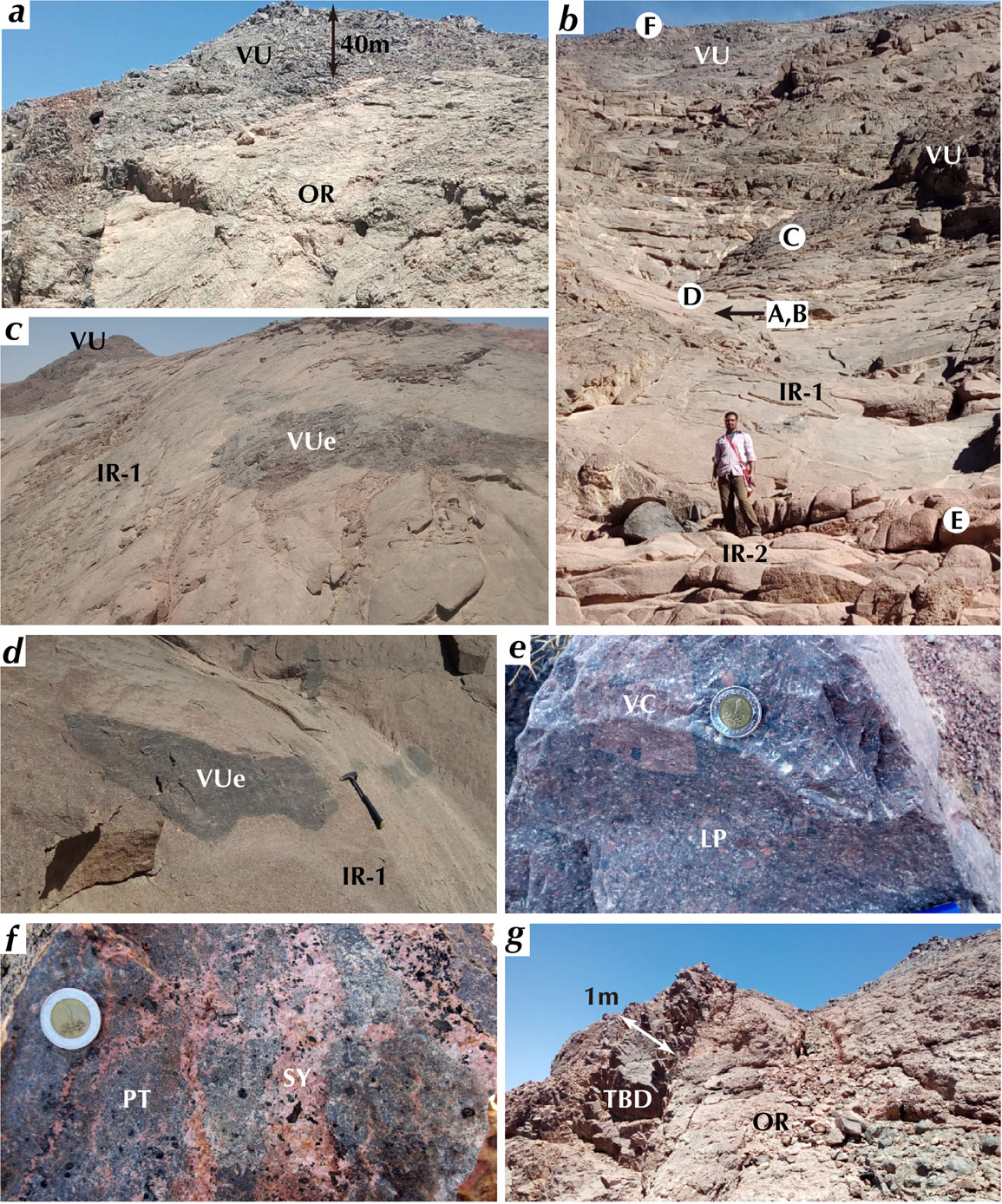
The volcanic unit occupies 15% of the distribution area of the WDRC, which is comparable to the mean area fractions occupied by volcanic rocks in ring complexes in the Eastern Desert (Table 1). The volcanic unit forms an intricately fractured crescent-shaped ridge with the main distribution area in the east of the complex thinning out towards the west leaving an isolated distribution forming a low ridge in the north (Fig. 3). At several outcrops on the inner side of the crescent distribution of the volcanic unit and their western isolated ridge we observed that the volcanic unit overlies both the outer ring (Fig. 4a) and inner ring 1 (Figs. 4b and 4c) with sharp either horizontal or gently dipping contacts. The relationship between the volcanic unit and the plutonic unit is inferred as illustrated in the cross sections (Fig. S2). The volcanic unit comprises pyroclastic rocks including volcanic breccia, lapilli tuff, and tuff (Fig. 4e). These units are dark gray with a reddish tint and very compact without vesicles when they occur as enclaves or blocks in the plutonic unit (Figs. 4c and 4d) or are within several tens of meters of the contact with the plutonic unit (Figs. 4b and 4c).
The plutonic unit occupies 85% of the entire area of the exposure of the WDRC (Fig. 3). The outer ring is the dominant lithology in the plutonic unit and occupies 55% of the exposed WDRC. It consists mostly of syenite with a grain size generally of a few millimeters, but locally reaching 2 cm. The outer ring is 700 m wide in the northwestern segment and 300 m in the eastern to southeastern segment, where the volcanic unit has a wide distribution (Fig. 3). Its width is unclear in the western and southwestern segment where the wadi deposit covers the outer ring. We did not observe any clear intrusive contact between the inner and outer rings, but observed faults near the western contact, which trend ∼ N-S almost concordant with the boundary between the outer and inner rings.
Various porphyritic rocks with a fine-grained matrix <1 mm in grain size occur as dikes in the southern segment of the outer ring. They show a wide variation in rock types ranging from syenite to syenogranite. Some of them show peculiar petrographic characteristics, such as olivine-phyric syenite and quartz and fayalite-bearing alkali feldspar syenite. In the following description such intrusive rocks in the outer ring are referred to as outer ring intrusive member to distinguish them from the main lithology of the outer ring. They are easily distinguished from rocks of the dike unit, which have groundmass much smaller in grain size than the matrix of the intrusive rocks.
We found a coarse-grained syenite in contact with a porphyritic trachyte with a fine-grained matrix (Fig. 4f). The porphyritic trachyte is cut by anastomosing veins of syenite, which may provide important information to constrain the order of formation of the volcanic unit and the outer ring, though this contact relationship was observed only in a loose block. The boundary will be examined in detail below in the petrography section to argue for the earlier formation of the volcanic unit and later formation of the outer ring in the discussion section.
The intrusive contacts against the country rocks, which are late Pan-African granodiorite-granite (Francis, 1972; Ghanem et al., 1973; Stern and Hedge, 1985), are generally sharp and are nearly vertical or dip steeply away from the core of the complex. We found granitoid blocks up to ∼ 50 cm in size in the outer ring ∼ 50 m from the contact with the country rocks in the southern end (D52; Figs. 5a-5c). The presence of abundant plagioclase shows that the blocks were derived from the country rock. The blocks have black-gray veins, which terminate at the contact with the host syenite (Figs. 5b and 5c). The contact is very sharp and there is no indication of reaction between the host and the xenolith. These features of the granitoid blocks indicate that the magma intrusion resulted in fragmentation of the country rock and the development of veined blocks in the outer ring. Granitoid of the country rock occurring near the contact with WDRC always has black-gray veins (D16A-C; Fig. 5d), which have similar petrographic features to those of the granitoid blocks in the outer ring.

Figure 5. Field photographs of granite/granodiorite blocks in the outer ring derived from the country rock observed near the contact with the country rock near locality D52 (a)-(c) and granite of the country rock sampled at D16 (d). (a) Outcrop view of the contact between the outer ring and country rock, indicated by two arrows pointing face-to-face, and sampling location of granite/granodiorite blocks of the country rocks, indicated by a large arrowhead. The blocks are situated ∼ 50 m away from the contact. (b) The entire view of the block with arrows indicating many veins running through the xenolith and terminating at the contact with the host syenite. The dashed rectangle indicates the area of (c). (c) A blow up of the lower part of (b) showing a small fragment barely separating from the main part with veins present on the extension from those in the main part and terminating at the contact with the host syenite. The surface in (b) and (c) was wetted to enhance the contrast between the block and its host as well as veins. (d) A cut surface of granite sampled at D16 having veins indicated with arrows. The thick dark-colored vein is filled mostly with amphibole, and the thinner vein is filled with feldspar and amphibole.
The inner ring occupies 19% of the exposure of the WDRC and is the second most abundant facies in the plutonic unit after the outer ring (Fig. 3). The width of the inner ring is 700 m in the northern segment, but this reduces to ∼ 200 m in the southern segment. The exposure of the outer ring is as wide as ∼ 200 m in the eastern segment, but the inner ring 1 may spread beneath the volcanic unit (Fig. S2), and the width beneath the surface is likely to be essentially the same in both the northern and eastern segments. The inner ring is subdivided into an inner ring 1 consisting of quartz-bearing syenite (modal quartz < 5 vol%) and making up 12% of the exposure of the WDRC and an inner ring 2 consisting of quartz syenite (modal quartz >5%) and making up 7% of the exposure of the WDRC (Fig. 3). We did not observe any sharp contact between the inner rings 1 and 2, thus we assume that they are transitional in the field. Enclaves or blocks of the volcanic unit with sizes ranging from a meter to a mappable size (∼ 100 m) are frequently observed in the inner rings particularly in the inner ring 1 (Figs. 3, 4c, and 4d).
The granitic core occupies 11% of the exposed WDRC and consists of alkali granite. The granitic core forms a topography characterized by the central hill surrounded by a circular depression of the inner ring and centered by a shallow depression (Figs. 3 and S2). No enclaves or blocks of the inner rings or the volcanic unit were observed. The contacts between the quartz syenite and the granite are transitional (Frisch and Abdel-Rahman, 1999).
The dike unit consists of trachybasalt, trachyte, and rhyolite dikes, which dip steeply and strike from N-S to NNW-SSE. These dikes crosscut rocks of the volcanic and plutonic units and are youngest in the WDRC. A composite dike consisting of trachybasalt and rhyolite, which have the most extreme chemical composition in the WDRC, intrude into the outer ring and the overlying volcanic unit crossing the boundary of the two units (Fig. 4g).
PETROGRAPHY
Petrography of representative rock types in the plutonic, volcanic, and dike units are described in this section based on thin section observations under an optical microscope for all samples and phase maps made from EPMA mapping of selected samples for the plutonic unit. See Suppl. Doc. (ANALYTICAL METHOD) for analytical method of EPMA analyses. The EPMA mapping was used to distinguish intermediate alkali feldspar, K-feldspar, albite, and oligoclase, the distinction of which is important to clarify petrographic features of feldspars in rocks from the plutonic unit. See Suppl. Doc. (PETROGRAPHY OF GRANITOIDS FROM THE COUNTRY ROCKS) for petrography of the country rocks and their enclaves occurring in the outer ring. Petrography of ungrouped samples is described in the end of Suppl. Doc. (PETROGRAPHY OF UNGROUPED SAMPLES).
Volcanic unit
The pyroclastic rocks belonging to the volcanic unit suffered from various degrees of recrystallization, which varies with the mode of occurrence. We examined 15 thin sections, and they are described by grouping into three according to their field occurrences: (1) enclaves or exotic blocks in the inner ring 1, (2) near either the outer ring or inner ring 1, and (3) distant from the plutonic unit. See Suppl. Doc. (PETROGRAPHY OF THE VOLCANIC UNIT) for more details and Supplementary Figure S3 for scanned images of entire thin sections of two representative pyroclastic rocks.
Pyroclastic rocks from (1) do not show distinct pyroclastic features, but sharply defined heterogeneities on the scale of up to 1 cm exhibited by local concentrations of certain minerals, such as amphibole, Fe-Ti oxide, and alkali feldspar, and local development of foliation around larger alkali feldspar grains mimicking trachytic texture indicate that they were originally pyroclastic fragments. Pyroclastic rocks from (2) show pyroclastic features under an optical microscope but is less conspicuous than those from (3). Volcanic fragments up to a few centimeters across have sharply defined outlines, which are identified either by local concentrations or reductions of mafic minerals or by volcanic rock microstructures. Polycrystalline aggregates consisting of greenish brown to brown amphibole or biotite with or without feldspar and Fe-Ti oxides are also present, which are inferred to be recrystallized crystal fragments of mafic minerals. Pyroclastic features are well-preserved in rocks from (3), which are easily recognizable under an optical microscope as fragments of trachyte showing typical trachytic texture and isolated crystal fragments of alkali feldspar, amphibole, and Fe-Ti oxides. The volcanic rock and crystal fragments are set in fine-grained matrix, irrespective of field occurrences (1)-(3).
The matrix of pyroclastic rocks from (1) has a weak foliation and consists mostly of alkali feldspar and brown to greenish-brown amphibole and Fe-Ti oxide with lesser amounts of biotite, titanite, and fluorite (Figs. 6a and 6b). Pale green clinopyroxene is common as a matrix mineral in some samples. The alkali feldspar in the matrix is equigranular, mafic minerals are euhedral/subhedral, and fluorite is anhedral and includes rounded alkali feldspars. The grain size of alkali feldspar and amphibole is 0.05 ± 0.03 mm. Crystal fragments of alkali feldspar, Fe-Ti oxide, and clinopyroxene set in the fine-grained matrix show significant modification from the rim. Crystal fragments of alkali feldspar are indented by matrix-size finer feldspar crystals from the margin (indicated by arrows in Fig. 6a) associated with matrix-size fine euhedral amphibole. Some of the crystal fragments exhibit wavy extinction and have tilt boundaries. Pale green clinopyroxene crystal fragments are rimmed with brown amphibole, and those of Fe-Ti oxide are rimmed with amphibole or indented by finer feldspar. These microstructures indicate recrystallization of the pyroclastic rock under stress.
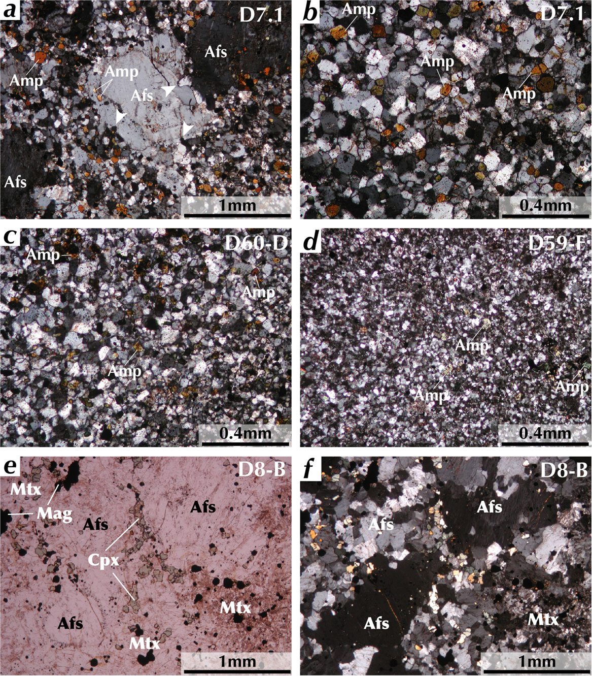
Figure 6. Photomicrograph showing microstructures of rocks from the volcanic unit. (a) Large crystal fragments of alkali feldspar having indentations of smaller matrix alkali feldspar (white arrows) and growth of euhedral amphibole along the margin in a volcanic enclave (D7.1) found in the inner ring 1 at locality D7. (b) Enlarged view of the matrix of (a) consisting mostly of alkali feldspar and is characterized by equigranular texture and euhedral amphibole. (c) Matrix of volcanic fragments and larger crystal fragments in lapilli tuff (D60-D) sampled from very close to the contact with the inner ring 1 at locality D60. The microstructure is characterized by euhedral amphibole and equigranular texture, the grain size of which is smaller than or comparable to that of (a). (d) Matrix of volcanic fragments and larger crystals in lapilli tuff (D59-F) sampled from high above the contact with the inner ring 1 at locality D59. The microstructure is characterized by euhedral amphibole and equigranular texture, the grain size of which is smaller than that of (b). (e) and (f) Phenocrysts of alkali feldspar in clinopyroxene and magnetite-dominant matrix (D8-B) sampled near the inner ring 1. The alkali feldspars are coarse grained and apparently subhedral when observed under plane polarized light (e) but consist of subgrains as seen in (f) under cross polarized light. Abbreviations are: Afs, alkali feldspar; Amp, amphibole; Cpx, clinopyroxene; Mag, magnetite or ilmenite; Mtx, matrix.
The matrix of pyroclastic rocks from (2) consists mostly of alkali feldspar and greenish brown - brown amphibole with lesser amounts of Fe-Ti oxides, biotite, apatite, clinopyroxene, and fluorite (Fig. 6c). The alkali feldspar in the matrix is equigranular, mafic minerals are euhedral-subhedral, and fluorite is anhedral including rounded inclusions. The grain size of alkali feldspar ranges from 0.1 to 0.01 mm. Crystal fragments of alkali feldspar shows similar recrystallization microstructures as observed in rocks from (1). Some crystal fragments of alkali feldspar have subgrains (Figs. 6e and 6f) indicating recrystallization under stress. Greenish brown to brown amphibole or biotite-rich polycrystalline aggregate has facetted outlines, indicating that they are pseudomorphs of mafic minerals.
The matrix of pyroclastic rocks from (3) has grain size of ∼ 0.01 mm (Fig. 6d). The matrix consists mostly of alkali feldspar, brownish green to green amphibole, clinopyroxene, and Fe-Ti oxides with lesser amounts of biotite and titanite. The alkali feldspar in the matrix is equigranular, clinopyroxene is anhedral to subhedral, and amphibole and Fe-Ti oxides are euhedral. Green amphibole (Al-poor hornblende) as large as 0.2 mm in size occurs in the matrix. Crystal fragments of alkali feldspar occurring in the matrix have euhedral outlines with minor indentation and overgrowth.
These microstructures and the field occurrence substantiate the inference that the exotic blocks in the inner ring 1 suffered recrystallization caused by heat released from the solidifying host quartz-bearing syenite or quartz syenite (pyrometamorphism). The microstructures of pyroclastic rocks of the volcanic unit similar to those of the exotic blocks in the inner ring 1 suggest that they also suffered the pyrometamorphism. The systematic variations of grain size of the recrystallized matrix (cf. Figs. 6b-6d), color of amphibole, and outline of pyroclastic rock and crystal fragments indicate that the grade of the pyrometamorphism of the volcanic unit decreases with distance from the plutonic unit.
Plutonic unit
We observed 50 thin sections from the plutonic unit under the optical microscope. The plutonic unit consists of a volumetrically dominant main lithology and minor intrusive rocks in the outer ring (outer ring intrusive member) and inner ring 2 (inner ring 2 intrusive member). Modal compositions are first explained, which is followed by description of microstructures. Petrographic characteristics of examined rocks are summarized in Tables 2 and 3. Petrographic details of the main constituent minerals are listed in Tables S2 and S3 for feldspars, in Table S4 for mafic silicate minerals, and in Table S5 for Fe-Ti oxides (ilmenite and magnetite). Thin section photomicrographs, phase maps, and Ca X-ray maps are presented in Figures S4-S6, respectively. Details of the petrography of the main lithology of the plutonic unit are found in Suppl. Doc. (PETROGRAPHY OF THE MAIN LITHOLOGY OF THE PLUTONIC UNIT). Petrography of the outer ring intrusive and inner ring 2 intrusive members is described in Suppl. Doc. (PETROGRAPHY OF THE INTRUSIVE MEMBERS AND UNGROUPED SAMPLES).
Table 2. Petrographic characteristics of rocks of the plutonic unit of the Wadi Dib ring complex
| Sample# |
Lithology group |
Location in each lithology group |
Distance
(km) |
IUGS ternary diagram (relative %) |
IUGS classification |
| A |
P |
Q |
| D14-C |
Outer Ring |
Outer margin |
1.35 |
75.3 |
24.7 |
0.0 |
Sodalite-bearing syenite |
| D1-A |
Outer Ring |
Inner margin |
0.79 |
74.4 |
25.6 |
0.0 |
Syenite (composite of alkali feldspar syenite and syenite) |
| D2 |
Outer Ring |
Inner margin |
0.73 |
58.5 |
41.5 |
0.0 |
Monzonite |
| D4 |
Inner Ring 1 |
Center |
0.54 |
71.0 |
23.4 |
5.6 |
Quartz syenite |
| D6.2 |
Inner Ring 2 |
Outer margin |
0.39 |
61.6 |
27.0 |
11.4 |
Quartz syenite |
| D5.3 |
Granitic Core |
Outer margin |
0.22 |
52.8 |
24.2 |
22.9 |
Syenogranite |
| D18-G |
Outer Ring |
Loose block |
- |
69.5 |
30.5 |
0.0 |
Syenite |
| D18-E |
Outer Ring |
Loose block |
- |
- |
- |
- |
Alkali feldspar syenite |
| D3-A |
Inner Ring 1 |
Center |
0.46 |
71.5 |
27.2 |
1.4 |
Quartz-bearing syenite |
| D58-B1 |
Outer Ring Intrusive ‡ |
Center |
0.59 |
93.2 |
6.8 |
0.0 |
Olivine-bearing alkali feldspar syenite |
| D15-B |
Outer Ring |
Outer margin |
1.10 |
89.6 |
10.4 |
0.0 |
Sodalite-bearing alkali feldspar syenite |
| D20-B |
Outer Ring Intrusive ‡ |
Outer margin |
0.65 |
86.7 |
1.4 |
11.8 |
Fayalite-bearing quartz alkali feldspar syenite |
| D55-B |
Outer Ring |
Outer margin |
1.14 |
62.6 |
37.4 |
0.0 |
Monzonite |
| D5.1 |
Granitic Core |
Outer margin |
0.22 |
54.6 |
25.3 |
20.1 |
Syenogranite |
| D5.2 |
Granitic Core |
Outer margin |
0.22 |
52.2 |
24.4 |
23.4 |
Syenogranite |
| D14-A |
Outer Ring Intrusive ‡ |
Outer margin |
1.35 |
60.8 |
19.5 |
19.7 |
Quartz syenite |
| D16-G |
Outer Ring Intrusive ‡ |
Outer margin |
0.76 |
94.7 |
5.2 |
0.1 |
Alkali feldspar syenite |
| D58-B2 |
Outer Ring Intrusive ‡ |
Center |
0.59 |
93.0 |
7.0 |
0.0 |
Olivine-bearing alkali feldspar syenite |
| D8-A |
Inner Ring 1 |
Outer margin |
0.66 |
74.2 |
22.2 |
3.6 |
Quartz-bearing syenite |
| D19-A |
Outer Ring Intrusive ‡ |
Outer margin |
0.63 |
58.8 |
26.2 |
15.0 |
Quartz syenite |
| Sample# |
Crystal
morphology† |
Size variation
pattern |
Deformation |
Foliation |
Vein type |
Quartz
micro-structure |
Peculiar points: contact, reaction microstructures, alteration, and etc. |
| D14-C |
Hypidiomorphic |
Bimodal |
Weak |
Mag moderate |
n.p. |
n.p. |
|
| D1-A |
Hypidiomorphic |
Bimodal |
Strong |
Mag weak/def weak |
Sheared vein |
n.p. |
|
| D2 |
Hypidiomorphic |
Bimodal |
Strong |
Mag very weak |
n.p. |
n.p. |
Olg rimmed by Kfs |
| D4 |
Idiomorphic |
Equisized |
Very weak |
Mag weak |
n.p. |
Interstitial |
|
| D6.2 |
Idiomorphic |
Sub-porphyritic |
Weak |
Mag weak |
n.p. |
Interstitial |
Fairly altered (calcite abundant) |
| D5.3 |
Idiomorphic/ micrographic |
Sub-porphyritic |
n.p. |
Mag very weak |
n.p. |
Micrographic |
Most extensive alteration |
| D18-G |
Hypidiomorphic |
Bimodal |
Weak |
Mag strong//contact |
n.p. |
n.p. |
In contact with porphyritic trachyte |
| D18-E |
Hypidiomorphic |
Equisized |
Weak |
Mag strong//contact |
Ab-Kfs intg vein |
n.p. |
In contact with porphyritic trachyte |
| D3-A |
Idiomorphic |
Equisized |
Weak |
Mag moderate |
n.p. |
Interstitial |
Isolated Cpx present |
| D58-B1 |
Idiomorphic |
Ol/Afs phyric |
Vein formation |
Mag strong |
Afs - Aeg-Aug vein |
n.p. |
Olivine rimmed with Cpx |
| D15-B |
Hypidiomorphic |
Equisized |
moderate |
Mag moderate |
Ab-Kfs intg vein |
n.p. |
|
| D20-B |
Idiomorphic |
Afs phyric |
n.p. |
Mag very weak |
n.p. |
Interstitial |
Ads at core of Afs; Fay and Amp complementary distribution |
| D55-B |
Hypidiomorphic |
Bimodal |
Weak |
Mag moderate |
n.p. |
n.p. |
Olg rimmed with Afs |
| D5.1 |
Idiomorphic |
porphyritic |
n.p. |
n.p. |
n.p. |
Interstitial * |
Olg-Ab pheno rimmed by Afs-Kfs |
| D5.2 |
Idiomorphic |
Sub-porphyritic |
Very weak |
Mag very weak |
n.p. |
Interstitial |
|
| D14-A |
Idiomorphic |
Equisized |
n.p. |
Mag moderate |
n.p. |
Subhedral |
Olg-Ads rimmed with Afs |
| D16-G |
Idiomorphic |
Afs phyric |
n.p. |
Mag moderate |
n.p. |
Secondary |
|
| D58-B2 |
Idiomorphic |
Afs, Cpx phyric |
Vein formation |
Mag moderate |
Afs - Aeg-Aug vein |
n.p. |
|
| D8-A |
Idiomorphic |
Sub-porphyritic |
Very weak |
Mag weak |
n.p. |
Interstitial |
Isolated Cpx present |
| D19-A |
Idiomorphic |
Sub-porphyritic |
n.p. |
n.p. |
n.p. |
Interstitial |
Olg rimmed by Afs |
Distances are measured from the geometric center of the granitic core. Modal abundance of D18-E cannot be determined because the sample has a limited area of the syenite lithology. A = Afs + Kfs + NaAb, P = CaAb + Olg + Ads, Q = Quartz. NaAb (Or = Orthoclase component <15%, An = Anorthite component <5%), Na-rich albite; CaAb (Or < 15, An < 5), Ca-rich albite; Ab (Or = Orthoclase component <16%, An = Anorthite component <10%), albite; Afs (15 < Or < 75), intermediate alkali feldspar; Kfs (Or > 75), near end component K feldspar; Olg (10 < An < 30), oligoclase; Ads (An > 30), andesine; Cpx, clinopyroxene; Aeg-Aug, aegirine-augite; Amp, amphibole; Ol, olivine; Fay, fayalite; ‡: ‘outer ring intrusive’ denotes ‘outer ring intrusive member’; intg, intergrowth; //, parallel to; def, deformation; Mag, magmatic. *: micrographic intergrowth locally present. †: based on phases predominant in modal abundance, mostly alkali feldspar; n.p., not present.
Table 3. Petrographic characteristics of mafic rocks and minor phases in the plutonic unit of the Wadi Dib ring complex
| Sample# |
Lithology group |
Major mafic phase in decreasing order (volume %) |
Minor phases* |
Clinopyroxene microstructure§ |
Amphibole microstructures§ |
| D14-C |
Outer Ring |
Amphibole (10.3), biotite (1.9), Cpx (0.6), Oxides (0.1) |
Sodalite, apatite, titanite, thomsonite, analcime, monazite, allanite, calcioancylite, calcite, pyrite, muscovite, topaz, no zircon found |
Subhedral rimmed by or anhedral included in Amp |
Subhedral |
| D1-A |
Outer Ring |
Amphibole (5.0), biotite (0.2), Oxides (0.2) |
Apatite, zircon, Ce-bearing epidote, baddeleyite, barite(Sr), pyrochlore, titanite, muscovite |
n.p. |
Anhedral w/ poikilitic margin common |
| D2 |
Outer Ring |
Amphibole (4.3), Cpx (0.1), Oxides (0.1), biotite (<0.1) |
Zircon, apatite, baddeleyite, zirconolite, monazite |
Subhedral - anhedral in reaction rim on Amp |
Anhedral w/ poikilitic margin common |
| D4 |
Inner Ring 1 |
Amphibole (4.0), biotite (0.2), Oxides (0.2) |
Zircon, apatite, thorite, titanite, Cu-Zn alloy |
n.p. |
Anhedral filling interstitial space |
| D6.2 |
Inner Ring 2 |
Amp partly replaced by Cal (1.8), Bt partly replaced by Chl (1.1), Oxides (<0.1) |
Apatite, zircon, fluorite, thorite, pyrochlore, calcite, chlorite (altered from biotite), rutile (in magnetite with ilmenite), Ce, La-bearing carbonate (alt?) |
n.p. |
Euhedral even in contact with quartz |
| D5.3 |
Granitic Core |
Biotite partly replaced by chlorite (1.8), amphibole (<0.1) |
Apatite, zircon (Th-poor and Th-rich), calcioancylite-(Ce) with lamellae of Ce analogue of kozoite-(La), (secondary minor phases: rutile, xenotime, etc.) |
n.p. |
Subhedral |
| D18-G |
Outer Ring |
Amphibole (3.8), biotite (0.2), Cpx (0.1), Oxides (<0.1) |
Apatite, zircon, titanite, pyrite, zirconolite, baddeleyite, muscovite, chamosite |
Anhedral in the core of Amp |
Subhedral - anhedral |
| D18-E |
Outer Ring |
Amphibole, biotite |
Not examined |
- |
- |
| D3-A |
Inner Ring 1 |
Amphibole (3.0), Cpx (0.8), biotite (0.7), Oxides (0.4) |
Apatite, zircon, fluorite, Ce-bearing epidote, thorite, pyrrhotite/pyrite, monazite, pyrochlore, sphalerite, Ti-Ca-Ce-Nb silicate (=D20-B) |
Euhedral isolated |
Anhedral filling interstitial space |
| D58-B1 |
Outer Ring Intrusive ‡ |
Cpx (7.1), amphibole (4.1), olivine (2.7), oxides (1.2), biotite (0.8), Aeg-Aug (0.4) |
Allanite, zircon, apatite, columbite (Y), Nb-Ca-Th-Ti-U silicate, pyrochlore (Ca niobate, fersmite? and Nb-Y oxide, polycrase?), Ce-La oxide |
Euhedral -subhedral, isolated or rimmed w/ Amp |
Extremely anhedral filling inters. space |
| D15-B |
Outer Ring |
Amphibole (9.4), Oxides (0.3), Cpx (0.2) |
Sodalite, apatite, thomsonite, analcime, zircon, titanite, baddeleyite, pyrochlore, Ce-Th-Ca silicate, monazite, pyrite, fluorite, calcite, pyrophanite |
Anhedral in Amp, euhedral - subhedral isolated w/ Olg, etc. |
Anhedral filling interstitial space |
| D20-B |
Outer Ring Intrusive ‡ |
F, Cl-rich amphibole (3.3), fayalite (0.1), Oxides (0.1), Cpx (<0.1) |
Fluorite, zircon, apatite, titanite, Ti-Ce-Nb-Th-Ca silicate [Chevkinite-(Ce) = D3-A], monazite. Cl, F-rich biotite |
Anhedral in Amph |
Subhedral - anhedral localized distribution |
| D55-B |
Outer Ring |
Amphibole (5.4), biotite (0.2), Cpx (<0.1), Oxides (<0.1) |
Zircon, apatite, baddeleyite, analcime, topaz, muscovite, titanite |
In Amp or isolated w/ thin rim of Amp |
Anhedral w/ poikilitic margin common |
| D5.1 |
Granitic Core |
Biotite (1.5), amphibole (0.2), Oxides (<0.1) |
Zircon, apatite, fluorite, thorite solid solution, calcioancylite, Ce-bearing epidote |
n.p. |
Euhedral, present in Qz |
| D5.2 |
Granitic Core |
Biotite (1.1), amphibole (0.1), Oxides (<0.1) |
Zircon, apatite, fluorite, thorite, pyrochlore, monazite, calcite, Nb-Ca-Ti-U-Na silicate |
n.p. |
Euhedral, present in Qz |
| D14-A |
Outer Ring Intrusive ‡ |
Amphibole (1.2), Oxides (0.6), Cpx (0.1) |
Allanite, zircon, apatite, columbite (Y), Nb-Ca-Th-Ti-U silicate, pyrochlore (Ca niobate, fersmite? and Nb-Y oxide, polycrase?), Ce-La oxide |
Subhedral and isolated |
Euhedral in Afs and Qz |
| D16-G |
Outer Ring Intrusive ‡ |
Amphibole (3.5), Cpx (1.3), Oxides (1.1) |
Zircon, apatite, baddeleyite, quartz (secondary probably after Cpx), barite (secondary) |
Euhedral and isolated |
Extremely anhedral intergrown w/ Afs |
| D58-B2 |
Outer Ring Intrusive ‡ |
Cpx (4.2), amphibole (4.2), Oxides (1.2), olivine altered (>0.1), Aeg-Aug (0.3) |
Apatite, zircon (very rare), baddeleyite, pyrochlore (or aeschynite, euxenite groups), muscovite (secondary), pyrite, britholite (Ce-Th phospho silicate) |
Euhedral -subhedral, isolated or rimmed w/ Amp |
Extremely anhedral filling inters. space |
| D8-A |
Inner Ring 1 |
Cpx (1.8), amphibole (1.6), biotite (0.5), Oxides (0.4) |
Zircon, apatite, pyrochlore (Nb-Ta-Th-Ca oxide)?, Nb-Th-(Ca, Ce) silicate?, Ti-Ce-Fe-Th-Nb silicate? |
Euhedral and isolated |
Anhedral filling interstitial space of Afs |
| D19-A |
Outer Ring Intrusive ‡ |
Amphibole (1.6), biotite (1.1), Oxides (<0.1) |
Fluorite, apatite, zircon, thorite (Zr, Y), Ce-La silicate?, Ce--La oxide? |
n.p. |
Euhedral and some included in Qz |
* Minor phases are arranged in the order of abundance. § See Table S4 for full information. ‡ ‘outer ring intrusive’ denotes ‘outer ring intrusive member’. Cpx, clinopyroxene; Aeg-Aug, aegirine-augite; Amp, amphibole; Afs, alkali feldspar; Qz, quartz; Oxides, Fe-Ti oxides; Chl, chlorite; Cal, calcite; n.p., not present.
We chose twenty representative samples for examination with EPMA and FE-SEM/EDS, based on which we distinguished three types of alkali feldspar and two types of plagioclase. They are K-feldspar [Kfs: Or (Orthoclase content) ≥ 75], intermediate alkali feldspar (Afs: 75 > Or > 15), albite [Ab: Or ≤ 15, An (Anorthite content) ≤ 5], Ca-rich albite (CaAb: 5 < An < 10, Or < 10), and oligoclase-andesine (Olg-Ads: An ≥ 10, Or < 10). The modal abundances of feldspars and quartz in the examined rocks are projected on the IUGS classification diagram for granitoid rocks (Streckeisen, 1974) by lumping Kfs and Afs together as ‘alkali feldspar’ (‘A’ in Fig. 7 and Table 2) and Ab, CaAb, Olg, and Ads as ‘plagioclase’ (‘P’ in Fig. 7 and Table 2).
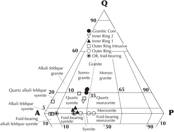
Modal composition of rocks from the plutonic unit. See Table S2 for modal abundances of each feldspar and quartz, Table 3 for mafic minerals, and Table S5 for ilmenite and magnetite. See also Suppl. Doc. (‘Modal abundances of mafic minerals in the main lithology of the plutonic unit’ in section PETROGRAPHY OF THE MAIN LITHOLOGY OF THE PLUTONIC UNIT) for details of modal compositions of mafic minerals. Rocks from the main lithology of the outer ring lack quartz and consists of sodalite-bearing alkali feldspar syenite, sodalite-bearing syenite, syenite sensu stricto, and monzonite according to the IUGS classification scheme (Table 2; Fig. 7). They show a wide variation in modal abundance of alkali feldspar (Kfs + Afs) ranging from 50 to 80 vol% and plagioclase (Ab + Olg + Ads) ranging from 10 to 40 vol%. Minor sodalite is present only in rocks with smaller amounts of plagioclase (Fig. 7). Rocks from the inner ring 1 contain a small amount of quartz <5 vol% and are classified as quartz-bearing syenite or quartz syenite according to the IUGS classification scheme (Table 2; Fig. 7). The modal abundances of alkali feldspar (Kfs + Afs) and plagioclase (Ab + Olg) show limited variations of 65-70 and 21-25 vol%, respectively. Olg is very minor (<0.1 vol%) and appears as a Ca-rich part of albite grains. Rocks from the inner ring 2 contain ∼ 11 vol% of quartz (Table S2) and are classified as quartz syenite according to the IUGS classification scheme (Table 2; Fig. 7). The modal abundances of alkali feldspar (Kfs + Afs) and plagioclase (Ab + Olg) are 60 and 26 vol%, respectively. Olg is very minor (1 vol%) and appears as locally Ca-rich parts in albite grains with CaAb (5 < An < 10) composition. Rocks from the granitic core contain abundant quartz as high as 20-23 vol% and are classified as syenogranite according to the IUGS classification scheme (Table 2; Fig. 7). The modal abundances of alkali feldspar (Kfs + Afs) and plagioclase (Ab + Olg), which are the most dominant phases, show limited variation ranging 41-54 and ∼ 24 vol%, respectively.
Major mafic minerals in rocks from the outer ring are amphibole, clinopyroxene, biotite, and Fe-Ti oxides, the modes of which are less than 12 vol% in total (Table 3). Olivine is generally absent in the main lithology of the outer ring, though it is present in a few samples from the outer ring intrusive member (Table 3). One exception is Fe and Ca-rich olivine (kirschsteinite) in the center of a composite inclusion in amphibole found in the sodalite bearing alkali feldspar syenite (D15-B). Mafic minerals in rocks from the inner ring 1 are amphibole, clinopyroxene, biotite, and Fe-Ti oxides (Table 3), the modes of which are less than 5 vol% in total. Olivine is absent in the inner ring 1. Mafic minerals in rocks from the inner ring 2 are amphibole, biotite, and Fe-Ti oxides (Table 3). Clinopyroxene as well as olivine are absent in the inner ring 2. Mafic minerals in rocks from the granitic core are amphibole, biotite, and Fe-Ti oxides (Table 3), the modes of which are less than 2 vol% in total. Olivine and clinopyroxene are absent in the granitic core. Biotite is the main mafic mineral in the granitic core, the mode of which ranges 1-2 vol% (Table 3).
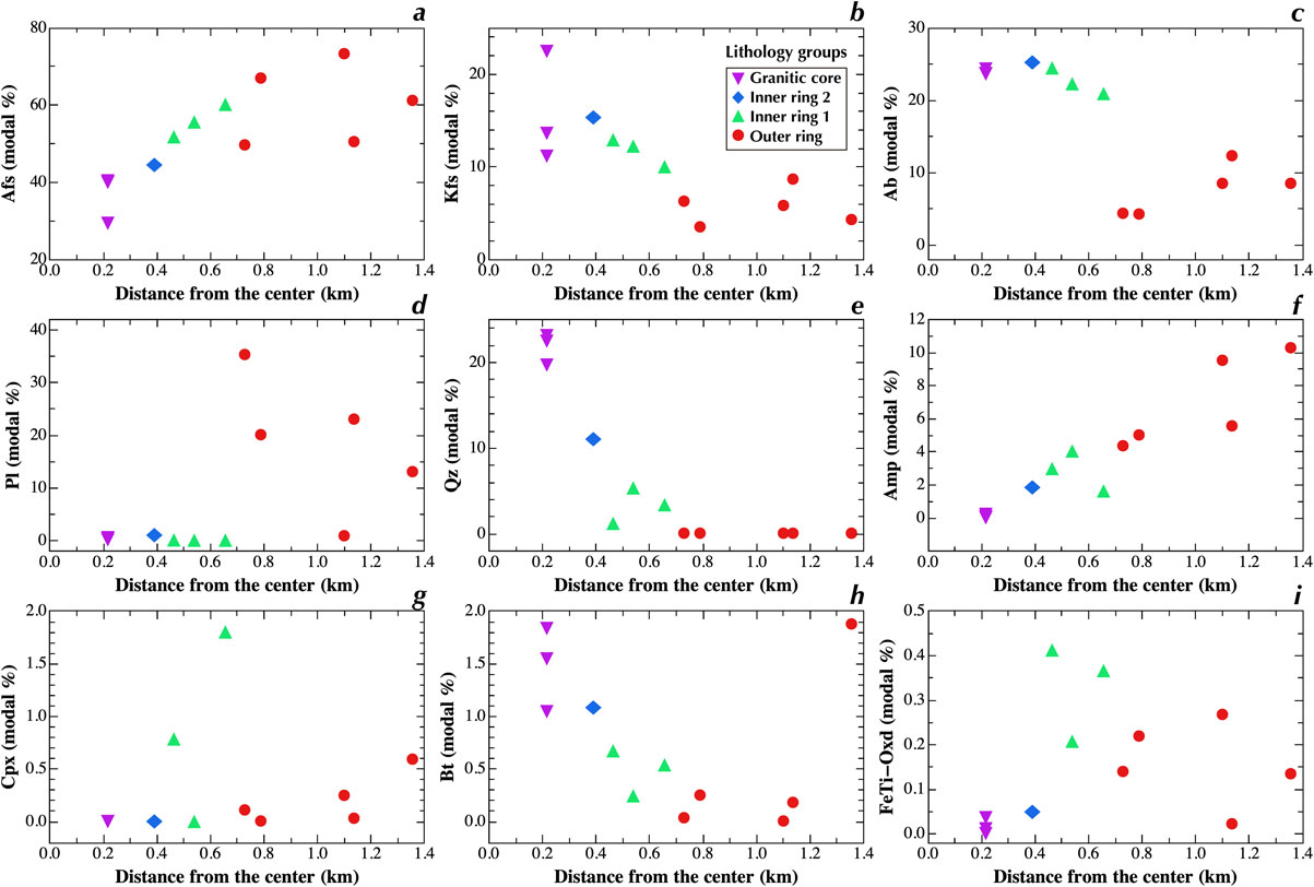
The spatial variations of modal abundances are shown in Figure 8, distinguishing four feldspars: Kfs, Afs, Ab + CaAb, and Pl = Olg + Ads. There are smooth and continuous variation throughout the complex for some minerals, such as decrease of Afs and amphibole (Figs. 8a and 8f), increase of Kfs, quartz, and biotite (Figs. 8b, 8e, and 8h) from the outer ring to the granitic core. Contrary to this, the modal variations of Ab, Pl, and clinopyroxene has a large gap between the outer ring and inner ring 1 (Figs. 8c, 8d, and 8g). The mode of Pl increases from the outer margin to the inner margin of the outer ring, then it drops to less than 1 vol% and then increases slightly from the inner ring 1 to the granitic core (Fig. 8d). The modes of Ab and clinopyroxene decrease from the outer margin to the inner margin of the outer ring and then abruptly increases at the boundary with the inner ring 1 (Figs. 8c and 8g). The mode of Ab shows a slight increase from the inner ring 1 to the granitic core. The mode of Fe-Ti oxide increases continuously through the boundary of the outer ring and the inner ring 1 and then abruptly decreases at the boundary between the inner rings 1 and 2 (Fig. 8i). Quartz is absent in the outer ring (Fig. 8e), whereas sodalite is present only in the outer ring.
Overall microstructure of rocks from the plutonic unit. See Figures S4-S6 for overall microstructures of 18 rocks from the plutonic unit examined in detail. Syenites, monzonites, and alkali feldspar syenite from the outer ring are hypidiomorphic, though they are not equisized plutonic rocks except for alkali feldspar syenite (Table 2; Figs. 9a and 9b). Quartz-bearing syenite from the inner ring 1 is idiomorphic, which is due to the equisized or sub-porphyritic microstructure with euhedral-subhedral alkali feldspar, the dominant phase (Table 2; Figs. 9a and 9b). Micrographic texture is very rarely observed. Quartz syenites from the inner ring 2 are idiomorphic (Table 2; Fig. 9a). They contain large crystals of alkali feldspar and albite sporadically distributed in finer matrix consisting of feldspar, interstitial quartz, and mafic minerals and are sub-porphyritic (Fig. 9b). Syenogranite from the inner ring 1 is idiomorphic and either sub-porphyritic or porphyritic (Table 2; Figs. 9a and 9b). Micrographic texture is developed in some samples of syenogranite (Fig. 9c).

Microstructure of feldspars in rocks from the plutonic unit. Feldspars from the plutonic unit show divers microstructures, details of which are described in Suppl. Doc. (‘Microstructure of feldspars’ in section PETROGRAPHY OF THE MAIN LITHOLOGY OF THE PLUTONIC UNIT) and Supplementary Figures (Figs. S7-S9). They are summarized in Table S3. One of the most conspicuous microstructures is development of intergrowth. There are three types of intergrowths. The first type is Olg and Afs intergrowth, which is developed in the outer ring (Figs. S7a, S7e, S7g, and S7i). The second type is Ab-Kfs intergrowth, which is present in all rocks from the plutonic unit (Figs. S8a-S8d, S9a-S9d, and S9h-S9l). The Ab-Kfs intergrowth is vermicular in the outer ring but is patchy in the inner rings and the granitic core (cf. Figs. S8a-S8d, S9a, and S9i). The third type is perthite microstructure consisting of alternations of Ab and Kfs on the scale smaller than a few tens of microns, which is developed in the inner ring 1, common in the inner ring 2 and the granitic core, and minor or absent in the outer ring (Figs. S8e, S8f, S9a-S9c, and S9i-S9l).
The scale of Ab-Kfs intergrowth shows a spatial variation (Figs. 10a and 10b). The scale is smaller than ∼ 0.1 mm in the outer ring and tends to decrease from the outer margin to the contact with the inner ring 1. There is a similar tendency in the inner rings and the granitic core. The sizes abruptly increase at the boundary of the outer ring and inner ring 1, and then slightly increase to the innermost inner ring 1 followed by a decrease to the granitic core (Figs. 10a and 10b). Qualitatively evaluated abundance of perthite increases from the outer ring to the granitic core with exceptional development in the inner part of the inner ring 1 (Fig. 10e).

The bimodal size distribution common in the syenite and monzonite of the outer ring (Fig. 9b) is manifested by the presence of ill-defined interstitial spaces between volumetrically dominant large feldspar grains, which are filled with volumetrically minor euhedral - subhedral small feldspar grains with minor mafic minerals (Figs. S7b, S7f, S7h, and S7l). The large feldspars from the outer ring are either Afs, Olg, or Olg-Afs intergrowth with size ∼ 4 mm (Fig. 11a). The small feldspars filling the interstitial space have grain size <0.3 mm (Fig. 11b). The size of large feldspars tends to increase and that of small feldspars tends to decrease in the outer ring from the margin to the contact with the inner ring 1 (Figs. 11a and 11b). The sizes abruptly increase at the boundary of the outer ring and inner ring 1. Feldspars from the inner rings and the granitic core are either Olg or Afs, whose size decrease from the inner rings to the granitic core.

Some alkali feldspar syenites from the outer ring has grain size of ∼ 1 cm, rarely reaching 2 cm (Fig. S7c). Frisch and Abdel-Rahman (1999) called the lithology as ‘pegmatitic syenite’, whose grain size is not plotted in Figure 11a. They have minor interstitial space of volumetrically dominant Afs, which is filled with Ab, calcite, biotite, and zeolite (Fig. S7d). The interstitial space of alkali feldspar syenite is distinguished from that of syenite and monzonite in that (1) the former interstitial space is more sharply defined, (2) its volume fraction and size are smaller, (3) more diverse mineral assemblage, and (4) the grain size of constituent minerals is smaller than the latter interstitial space.
The remarkable feature in the spatial variations of grain size of feldspars and scale of Ab-Afs intergrowth is the presence of notable gaps between the outer ring and inner ring 1 (Figs. 11a, 11b, 10a, and 10b), which suggests a significant event took place between the formation stages of the outer ring and the inner ring 1. The gaps are also clearly seen in spatial variations of overall microstructures (Fig. 9a), size variation types (Fig. 9b), the presence or absence of interstitial quartz (Fig. 9c).
Feldspar in rocks of the granitic core shows diverse microstructures, which is thoroughly described in Suppl. Doc. (‘Granitic core’ in subsection of ‘Microstructure of feldspars’ in section PETROGRAPHY OF THE MAIN LITHOLOGY OF THE PLUTONIC UNIT) and Figures S9h-S9l. Some of them are peculiar and important to constrain thermal environment for the formation of the granitic core. Irregular patchy intergrowth of Kfs-Ab in the core with or without margin of regularly spaced perthite is common. Some grains of this type have an internal structure consisting of two sectors: one is Ab-Kfs intergrowth along long axis and the other is perthite along short axis (Figs. S9k and S9l), which indicates that the alkali feldspar had a sector zoning before decomposition into two feldspars. Elongate feldspar consisting of Afs-Ab intergrowth and elongate zone or zones of CaAb-Olg along the center, along the margin, or in between is observed (Fig. S9h). The elongate crystal shows sector pattern of Ab-Kfs intergrowth and perthite as well as hollow crystal morphology filled with quartz.
Microstructure of mafic minerals in rocks from the plutonic unit. Mafic minerals from the plutonic unit show diverse microstructures. Here microstructures of amphibole and clinopyroxene, two of the most abundant mafic minerals in the plutonic unit, are described. Microstructures of biotite and Fe-Ti oxides are briefly summarized below. See Suppl. Doc. (‘Microstructure of mafic minerals’ in section PETROGRAPHY OF THE MAIN LITHOLOGY OF THE PLUTONIC UNIT), Figures S9e-S9f, and Tables S4-S5 for details of microstructures of mafic minerals.
Amphibole is subhedral to anhedral in rocks from the outer ring, inner ring 1, and inner ring 2 (Figs. 12 and 13) but is euhedral in the granitic core. The pleochroism of amphibole changes from the margin to the center of the WDRC: green to brown pleochroism turning into greenish towards the margins in the outer ring (Figs. 12a, 12c, and 12e), brownish green-green, and locally turning into more greenish with a bluish tint towards the margins in the inner ring 1, brownish green-pale brown becoming greenish and locally green towards the margin in the outer ring 2, and pale to bright brownish green in the granitic core.

Figure 12. Modes of occurrences of amphibole and associated clinopyroxene in rocks from the plutonic unit observed with optical microscope under plane-polarized light. Aggregate of amphibole with many inclusions of euhedral apatite and magnetite and anhedral clinopyroxene sharing c-axis with the host (a), amphibole rimming subhedral clinopyroxene (b), amphibole containing anhedral clinopyroxene grains having the same crystallographic orientation and in topotaxy relationship with the host (c), amphibole with indented surface morphology in contact with fine-grained feldspars (d), amphibole having poikilitic margin containing euhedral feldspars (e), and extremely poikilitic amphibole containing small grains of euhedral - subhedral feldspars, ornamented with beads of magnetite, and occurring in contact with sheared vein (f). No distortion of crystals is observed in the poikilitic amphibole grains in (e) and (f) even if they are in contact with fine-grained zone or sheared vein. Afs, intermediate alkali feldspar (15 < Or < 75); Amp, amphibole; Cpx, clinopyroxene; Bt, biotite; Apt, apatite; Mag, magnetite; Ttn, titanite; V, void.
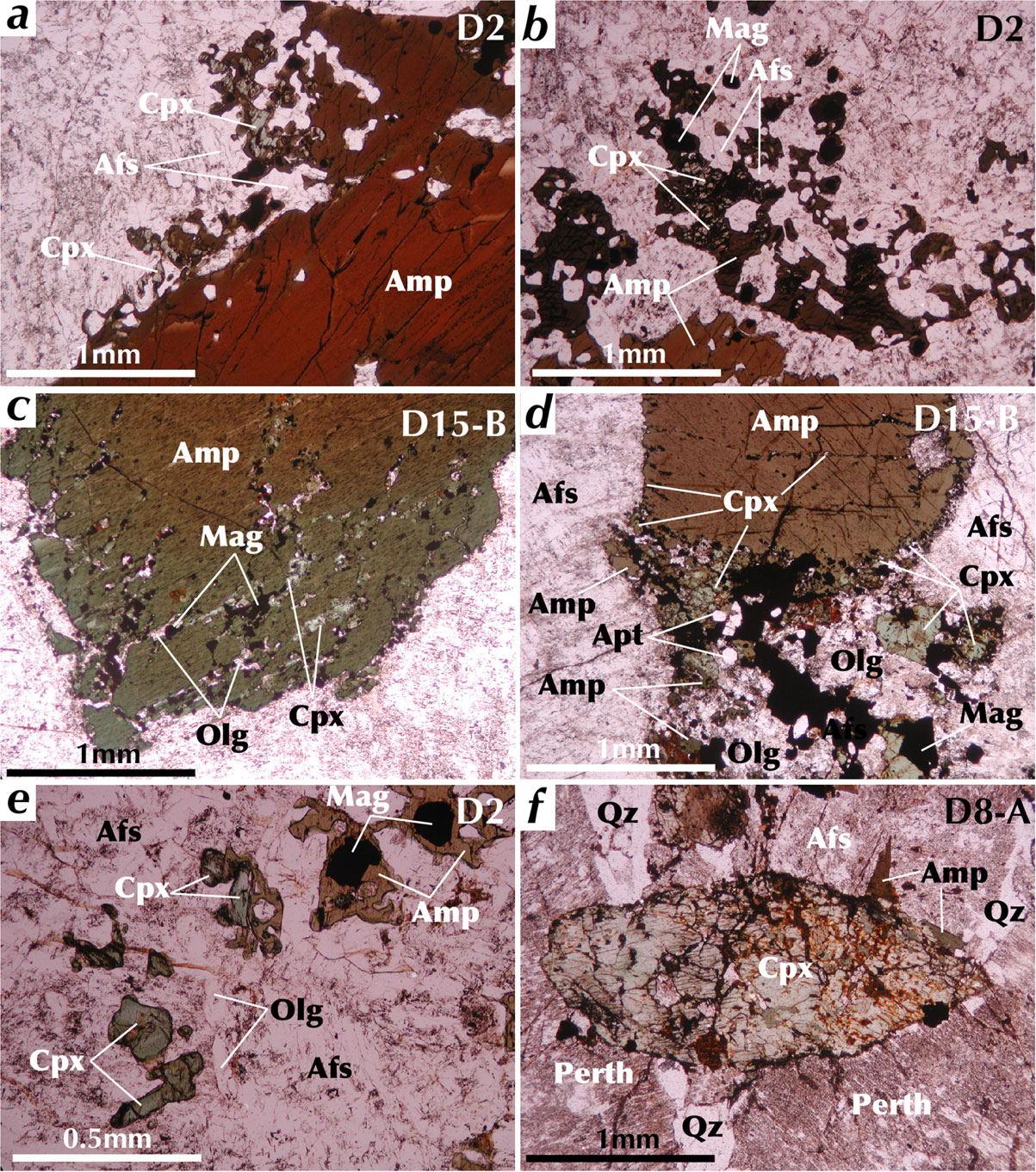
Amphibole appears either as isolated grains, forming aggregates (Fig. 12a), or rimming large subhedral grains of clinopyroxene sharing crystallographic c-axis in the outer ring (Fig. 12b). It commonly includes anhedral clinopyroxene with or without shared crystallographic c-axes (Figs. 12a and 12c) and euhedral Fe-Ti oxide and apatite (Figs. 12a, 12c, and 12d). Amphibole fills interstitial space of euhedral Afs and euhedral-subhedral clinopyroxene accompanied by quartz, biotite, Fe-Ti oxide, fluorite, albite, and apatite in the inner ring 1. Amphibole occurs filling interstitial space with quartz in direct contact, rarely as euhedral grains forming aggregate with albite and biotite in the inner ring 2. Amphibole occurs in contact with or in quartz in the granitic core. It is peculiar in the granitic core that euhedral amphibole grains are surrounded by or included in anhedral quartz filling the interstitial space of Afs (Figs. S9e and S9f).
In the outer ring, amphibole shows diverse morphologies and microstructures in the grain margin: (1) a compact margin with straight or indented (on the scale <0.2 mm) morphology (Figs. 12a and 12d), (2) a poikilitic margin including subhedral feldspars (Figs. 12e and 12f), (3) a poikilitic margin with clinopyroxene showing a topotactic relationship (Figs. 13a and 13b), and (4) a spongy margin associated with clinopyroxene, magnetite, and feldspar with or without outermost rim decorated with clinopyroxene and magnetite (Figs. 13c and 13d). The morphology (1) coexists with one of (2)-(4) in each sample and even within a single grain (Figs. 12e, 13a, and 13b). In the granitic core, extremely elongate amphibole crystals (aspect ratio is up to ∼ 20) occur (Fig. S9f). The long axe tends to orient nearly parallel to those of elongate alkali feldspar. Such elongate crystals show microstructure resulted from fracturing and subsequent ‘pull apart’, which separates elongate amphibole into up to 4 segments. The pull apart space, up to 0.1 mm in width, is filled with quartz or alkali feldspar.
Clinopyroxene in rocks from the outer ring is subhedral to anhedral and is pale green. Clinopyroxene from the inner ring 1 is euhedral-subhedral and is pale green (Fig. 13f) with more greenish margin in some grains. Clinopyroxene is absent in the inner ring 2 and in the granitic core. Clinopyroxene shows three modes of occurrence in the outer ring (Table 3): (1) small anhedral grains (<0.5 mm) occurring in much bigger amphibole grains as inclusions (Figs. 12a and 12c); (2) large grains (up to 1.5 mm) of subhedral clinopyroxene rimmed by amphibole (Fig. 12b); (3) anhedral-subhedral clinopyroxene (<0.2 mm) present in poikilitic or spongy margin of amphibole and its vicinity (Figs. 13a-13c); and (4) anhedral clinopyroxene as large as 0.2 mm occurring in crystal aggregates consisting of magnetite, oligoclase, and apatite apparently replacing amphibole maintaining the outline of amphibole (Fig. 13d). Clinopyroxene and amphibole in direct contact with each other are mostly in topotactic relationship irrespective of the mode of occurrence.
Clinopyroxene from the inner ring 1 occurs in interstitial space of large Afs crystals with quartz, amphibole, and feldspars as an isolated grain mostly without amphibole rim. Euhedral clinopyroxene in direct contact with quartz is very common (Fig. 13f). Anhedral clinopyroxene occurring as inclusions in amphibole, which is common in the outer ring, is very rare and only a few grains are found in the inner ring 1.
The maximum size of amphibole tends to increase first in the outer ring and then continuously decreases from the middle of the outer ring to the boundary with the inner ring 1 (Fig. 11d). It increases again from the innermost inner ring 1 attaining the maximum in the innermost inner ring 1 followed by decrease to the granitic core (Fig. 11d). The maximum size of clinopyroxene decreases in the outer ring towards the boundary with the inner ring and abruptly increases at the boundary between the outer ring and inner ring 1 followed by decrease in the inner ring 1 (Fig. 11c). Clinopyroxene is absent in the inner ring 2 and the granitic core. The maximum size of biotite does not show any clear variation trends excepting extremely large size in the outermost outer ring (Fig. 11e). The maximum size of Fe-Ti oxide (magnetite) abruptly decreases at the boundary of the inner rings 1 and 2 after increasing in the outer ring and inner ring 1 from the outer margin of the outer ring (Fig. 11f). The variation pattern is similar to that of modal abundance of Fe-Ti oxides (Fig. 8i).
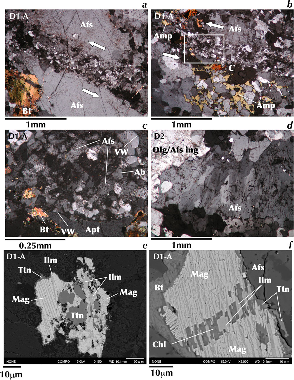
Iron-titanium oxides are either magnetite with ilmenite lamellae or ilmenite. Their microstructures are presented in Figure S10 and tabulated in Table S5. Ilmenite tends to occur on the rim of magnetite in direct contact in rocks from the main lithology of the outer ring. Isolate ilmenite grains are absent in the outer ring, rare in the inner ring 1, and abundant in the inner ring 2 and the granitic core. Ilmenite lamellae in magnetite show diverse morphologies and thicknesses. There are two types of ilmenite lamellae: (1) homogeneously and densely distributed fine ilmenite lamellae (Fig. S10a) and (2) sporadic thick ilmenite lamellae with fine lamellae in magnetite sandwiched by the thick ilmenite lamellae (Fig. S10b). The thickness of thick ilmenite lamellae tends to decrease from the inner ring 1 to the granitic core (no thick lamellae) after the inward steady increase in the outer ring (Fig. 10c) excepting rare grains of anomalously thick lamellae in the inner ring 1. The thickness of fine lamellae is scattered but there is overall increasing tendency from the outer ring to the granitic core (Fig. 10d). The maximum thickness of the thin ilmenite lamellae is registered in the innermost inner ring 1.
The remarkable feature in the spatial variation of microstructures of mafic minerals is the presence of significant gaps between the outer ring and inner ring 1 (e.g., Figs. 10c and 11c), which is also noticed above in the spatial variations of grain size of feldspars, scale of Ab-Afs intergrowth, overall microstructures, and size variation types. This suggests a significant event took place between the formation stages of the outer ring and the inner ring 1.
Planar microstructure of rocks from the plutonic unit. Rocks from the plutonic unit mostly shows weak foliation (Table 2). Foliations identified by criteria listed in Table S6 for examined rocks are indicated by white lines with arrow heads in Figure S4. One exception is fine-grained sample from the granitic core, which has negligible foliation. The foliations are defined by: (1) shape preferred orientation of elongate crystals of alkali feldspar, oligoclase-alkali feldspar intergrowth, or mafic minerals, (2) preferred alignment of elongate mineral aggregates consisting of mafic minerals or quartz ± mafic minerals, and/or (3) <∼ 5 mm thick bands with higher abundance of mafic minerals. The foliation is moderate in the outer part of the outer ring and is weak in its inner part (Fig. 9d), particularly in the granitic core.
Deformation related microstructures in rocks from the plutonic unit. Rocks from the outer ring (main lithology) underwent deformation to various extents, which is identified by the following features: (1) sheared veins (Figs. 14a-14c); (2) strained alkali feldspar and biotite, as shown by the presence of wavey extinction and development of subgrains or tilt boundaries (Fig. 14d); (3) distortion of ilmenite lamellae in magnetite (Fig. 14e); (4) pull-apart microstructures of magnetite with ilmenite exsolution lamellae (Fig. 14f); (5) alignment of strained feldspars (deformation-related foliation white arrows in Fig. S5c); and (6) grain boundary migration. See Suppl. Doc. for details of deformation microstructures (1)-(6) (‘Details of deformation-related microstructures’ in section PETROGRAPHY OF THE MAIN LITHOLOGY OF THE PLUTONIC UNIT). All samples from the outer ring have at least (2) with or without subgrains or tilt boundaries. Significant deformation is observed in two samples from the inner margin of the outer ring (Fig. 9e), which have most of the above deformation features. Other samples from the outer ring that only have (2) are evaluated to have undergone moderate to weak deformation depending on the degree of development of subgrain microstructure.
Degree of deformation increases from the outer margin to the inner margin of the outer ring (Fig. 9e). It suddenly decreases at the boundary with the inner ring 1 followed by a slight increase towards the boundary with inner ring 2. The granitic core show microstructure suggesting weak or no deformation (Fig. 9e). Veins cross cutting the major constituent minerals are observed only in the outer ring (Fig. 9f).
Contact relationship between syenite and porphyritic trachyte. We found loosed blocks, in which anastomosing veins of coarse-grained syenite occur in porphyritic trachyte with fine-grained groundmass at locality D18 (Fig. 4f). They provide crucial information to clarify the relationship between the volcanic unit and the outer ring. Petrography of these rocks are summarized below. See Suppl. Doc. (‘Contact relationship between syenite and porphyritic trachyte’ in section PETROGRAPHY OF THE MAIN LITHOLOGY OF THE PLUTONIC UNIT) and Figures S11 and S12 for the details.
In examined samples, alkali feldspar syenite or syenite is in contact with porphyritic trachyte. The petrographic characteristics of the alkali feldspar syenite consisting dominantly of Afs and that of the syenite consisting dominantly of Olg-Afs intergrowth are essentially the same as their counterparts in the main lithology of the outer ring described above. Foliation is clearly defined by shape preferred orientation of elongate Afs or Olg-Afs intergrowth and is parallel to the boundary with porphyritic trachyte (Fig. 15).

The groundmass of the porphyritic trachyte shows an equigranular microstructure (Figs. 15e and 15f). It consists mainly of Afs and amphibole with minor amounts of magnetite, clinopyroxene, Ab-Olg, and Kfs. Feldspars and amphibole show shape preferred orientation (see Figs. 15f and 15e, respectively). With the exception of the shape preferred orientation and larger grain size, the petrographic features of the groundmass are the same as those of pyroclastic rock blocks occurring in the inner ring 1 (cf. Figs. 15f and 6b), suggesting that the porphyritic trachytes underwent the same pyrometamorphism as observed in the volcanic unit. Phenocrysts are predominantly Afs, the morphologies of which are preserved with some degree of modification despite extensive recrystallization. The modification includes indented outlines due to recrystallization and invasion by fine-grained euhedral amphibole of the matrix. The phenocrysts of clinopyroxene and Fe-Ti oxide are rimmed with amphibole and biotite. Some of the Afs phenocrysts are strained and show wavy extinction and development of tilt boundaries. Combining the thin section observations explained above and in the Suppl. Doc. and the field occurrence of anastomosing veins of the syenite in the porphyritic trachytes (Fig. 4f), we conclude that the syenitic magma solidified as it intruded into already solidified porphyritic trachyte having induced its recrystallisation and pyrometamorphism probably accompanied by partial melting. See Suppl. Doc. (‘Contact relationship between syenite and porphyritic trachyte’ in section PETROGRAPHY OF THE MAIN LITHOLOGY OF THE PLUTONIC UNIT) for evidence of partial melting.
Dike units
The dike units consist of rocks with diverse chemical compositions: trachybasalt, basaltic trachyandesite, trachyte, and rhyolite. The petrography of trachybasalt, which is the least fractionated dike rock, is described in this subsection. The petrography of other dike rocks, which were analyzed for major element compositions, is described in Suppl. Doc. in addition to details of petrography of the trachybasalts (PETROGRAPHY OF THE DIKE UNIT). Additional photomicrographs for trachytic texture and skeletal pseudomorphs found in trachybasalts are presented in Figure S13.
Trachybasalt. Trachybasalts are mostly aphyric consisting dominantly of fine to medium-grained groundmass (Fig. 16). They suffer from low-temperature metamorphism indicated by the presence of secondary minerals, such as epidote, chlorite, actinolite, titanite, and calcite, the mineral assemblage of which suggests green schist facies metamorphism (e.g., Figs. 16a and 16b). One trachybasalt sample has no phenocrysts (Figs. 16a and 16b), and its groundmass consists of euhedral elongated laths of alkali feldspar 0.5 mm in length, which are aligned to exhibit trachytic texture, pale green clinopyroxene, biotite, euhedral Fe-Ti oxide, and acicular apatite. A few alkali feldspar phenocrysts ∼ 2 mm long (Fig. 16c) and clinopyroxene microphenocrysts 0.5 mm in size are present in the other sample (Fig. 16d). The clinopyroxene microphenocrysts have reddish brown - pale brown pleochroism and euhedral-subhedral morphology. The trachybasalt has aggregates consisting of titanite, carbonate, and albite with acicular actinolite extending inside from the margin (Figs. 16e and 16f). They have facetted outlines mimicking the morphology of olivine. Skeletal pseudomorphs ∼ 0.2 mm in length and consisting of titanite are also present, which mimics morphology of skeletal olivine crystal.
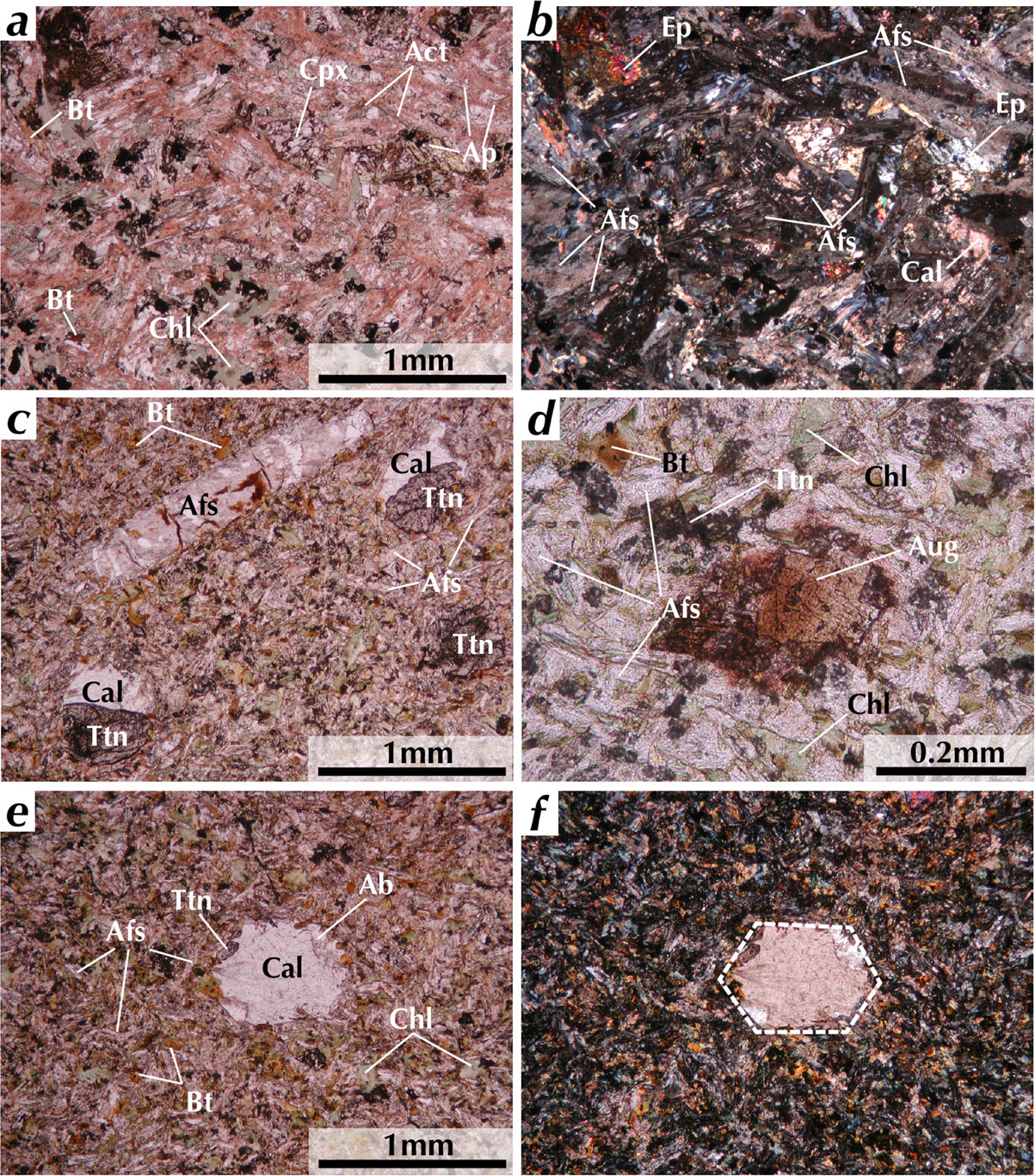
Figure 16. Thin section photomicrograph of rocks from the dike unit. Aphyric trachybasalt D18-J showing trachytic texture (a) and (b). Trachytic texture is defined by alignment of alkali feldspar laths (see also Figs. S13a and S13b). Aphyric trachybasalt D56-A showing rare alkali feldspar phenocryst (c), brownish titan augite microphenocryst (d), an aggregate consisting of calcite, albite, and titanite (e) and (f). (a) and (c)-(e) are observed under plane polarized light, and (b) and (f) are observed under cross polarized light. In (f) the aggregate has faceted outline mimicking euhedral olivine morphology. Cpx, clinopyroxene; Bt, biotite; Chl, chlorite; Ap, apatite; Act, actinolite; Afs, alkali feldspar; Cal, calcite; Ep, epidote; Ttn, titanite; Aug, augite.
WHOLE ROCK MAJOR ELEMENT COMPOSITION
Whole rock major element concentrations of 40 samples from the WDRC were determined. See Suppl. Doc. (ANALYTICAL METHOD) for details of analytical method. The oxide wt% data are listed in Table S7 and plotted in total alkali-silica (TAS) diagram in Figure 17 and in Harker variation diagrams in Figure 18. Their petrographic details for all samples are available in Tables 2, 3, and S2-S5 and Suppl. Doc. (sections on ‘PETROGRAPHY’ for the WDRC). Most of the rocks from the outer ring are olivine and nepheline normative (1.0-6.9 and 0.2-4.2 wt%, respectively). Quartz-bearing syenites of the inner ring 1, quartz syenite from the inner ring 2, and syenogranites from the granite core (ring 5) are quartz normative (0.5-30.6 wt%). All trachybasalts from the dike unit are olivine and nepheline normative (3.3-17.5 and 0.8-3.4 wt%, respectively), whereas basaltic trachyandesite and trachyte from the two units are olivine and hypersthene normative.
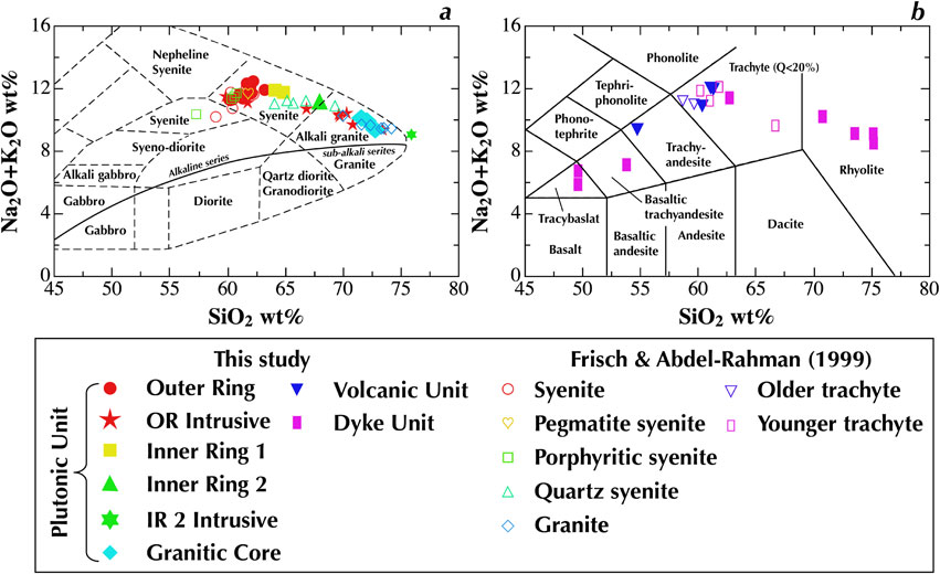

All samples from the outer ring and inner ring 1 are high in total alkali (Na2O + K2O > 11.2-12.2 wt%) and plotted in the syenite field in the TAS classification diagram after Cox et al. (1979) adapted by Wilson (1989) for plutonic rocks (Fig. 17a). Samples from the inner ring 2 and granitic core are low in total alkali (Na2O + K2O = 9.0-10.4 wt%) and plotted in the alkali granite field. Rocks from the volcanic and dike units show consistent variations and are plotted in trachybasalt, basaltic trachyandesite, trachyandesite, trachyte, and rhyolite fields according to the classification of Le Bas et al. (1986) (Fig. 17b). The total alkali content first increases from 5 to 13 wt% with increase in SiO2 from 50 to 62 wt%. With further increase in SiO2 to 77 wt%, the total alkali decreases from 13 to 8 wt%. Our data (filled symbols in Fig. 17) are essentially consistent with those reported by Frisch and Abdel-Rahman (1999) (open symbols in Fig. 17). All data from the plutonic, volcanic, and dike units form a consistent trend in the TAS diagram (Fig. 18j).
In the Harker variation diagrams shown in Figure 18, all the data from the WDRC including those reported by Frisch and Abdel-Rahman (1999) form a broadly consistent trend with some outliers, particularly several data from the literature. The common trend consists of two linear segments, which meet at an inflection point at SiO2 ∼ 62 wt%. The Al2O3, Na2O, and K2O contents increase with increasing SiO2 up to 62 wt% and then decreases with further increase in SiO2 up to 77 wt% (Figs. 18b, 18g, and 18h). All the other oxide contents continuously decrease with increase in SiO2 from 50 up to 77 wt% with changes in slopes in the Harker diagrams at SiO2 = 62 wt% (Figs. 18a, 18c-18f, and 18i). Their slopes are steeper below 62 wt% SiO2 than those above 62 wt% SiO2. The changes in slope either side of the inflexion point decrease in the order of MgO, TiO2, P2O5, CaO, Fe2O3, and MnO. The FeOt/(MgO + FeOt), where FeOt is the total Fe as FeO, plotted against SiO2 content shows a similar variation pattern to that of Na2O and K2O (Fig. 18k). The value sharply increases with increase in SiO2 up to 62.5 wt% followed by gentle decrease with further increase in SiO2. Such variation pattern in Harker diagrams is noticed in the TAS diagram of Frisch and Abdel-Rahman (1999) and has been reported from world alkaline igneous provinces (e.g., Downes, 1987; Fitton 1987; Liégeois and Black, 1987; Upton and Emeleus, 1987; Woolley and Jones, 1987; Edwards and Russell, 2000). Careful inspection of the Harker diagrams reveals that some of the data from the outer ring (red and open circles) plot off the overall trends. These samples are syenites from the outer ring and have higher Al2O3, lower Fe2O3 and MnO, slightly higher Na2O contents than the overall trends (Figs. 18b-18d, 18h, and 18g).
Major oxide contents of the main lithology of the plutonic unit are plotted against distance from the center in Figure 19. Because of the systematic distribution of lithologies: syenite, quartz-bearing syenite, quartz syenite, and syenogranite from the margin to the center of the WDRC, there are systematic variations of the concentrations of major oxides. The SiO2 content slightly increases in the outer ring with decreasing distance from the center followed by a linear and sharp increase with approaching the complex center (Fig. 19a), which is consistent with the variation of quartz mode (Fig. 8e). The whole-rock Fe2O3 and MnO contents show a linear overall increase from the center to the margin with data points for the inner ring 1 shifted above the overall trend (Figs. 19d and 19e). The Al2O3 and Na2O contents tend to increase in the outer ring followed by a remarkable decrease with decreasing the distance from the center (Figs. 19c and 19h). The TiO2 and P2O5 contents show an overall decrease with approaching the center with two outliers in the outer ring showing lower values than the overall trend (Figs. 19b and 19j). The MgO and CaO contents also show an overall decrease with approaching the center with two outliers in the innermost outer ring showing higher values than the overall trend (Figs. 19f and 19g). The K2O content is scattered in the outer ring but shows an overall decrease with approaching the center.

DISCUSSION
Formation sequence of the Wadi Dib ring complex (WDRC)
Updated formation sequence. Two formation sequences were proposed in the previous studies, which are inconsistent with one other. The details are explained in Suppl. Doc. (‘Formation order of the WDRC in previous studies’ in section SUPPLEMENTARY MATERIALS FOR DISCUSSION). We confirmed the formation sequence proposed by Frisch and Abdel-Rahman (1999) except for the volcanic unit, which was presumed to be younger than the outer ring in the literature (Fig. S2a). Age relationship between the outer ring and the volcanic unit must be resolved for proper reconstruction of the formation process of the WDRC.
We found an anastomosing network of coarse-grained syenite with patches of amphibole in pyrometamorphosed porphyritic trachyte (Fig. 4f). The field relationship and microscopic contact relationships examined under thin section and EPMA mapping analyses (Fig. 15) provide unequivocal evidence for intrusion of a syenite magma into already solidified porphyritic trachyte. Petrography of the syenite and the porphyritic trachyte demonstrates that the former belongs to the outer ring and the latter to the volcanic unit. The volcanic unit underwent pyrometamorphism, the degree of which varies with the distance from the plutonic unit irrespective of the inner and outer rings (Figs. 6b-6d). Our field observations show that the volcanic unit overlies the outer ring at southern part of the WDRC (Figs. 4a and S2). We thus conclude that the volcanic unit predated the outer ring and suffered pyrometamorphism by the heat originated from the solidifying outer ring.
This age relationship between the volcanic unit and the outer ring is supported by the fact that volcanic unit consists dominantly of pyroclastic rocks (Fig. 4f), requiring subaerial volcanism accompanied by rapid cooling (El Ramly et al., 1976; Frisch and Abdel-Rahman, 1999). Contrary to this, the plutonic unit, characterized by coarse-grained hypidiomorphic to sub-porphyritic microstructures, requires slower solidification at a depth where rapid cooling is inhibited. There are no reasonable physical processes for the volcanic unit dominated by pyroclastic rocks to have emplaced into the outer ring as argued by Frisch and Abdel-Rahman (1999) and later to have suffered from pyrometamorphism. Therefore, the direct contact between the plutonic unit and the volcanic unit can be explained only by subsidence of volcanic rocks to deeper level to have contact with solidifying magma after the formation of the volcanic unit on the surface. Revised formation sequence of the WDRC started with the volcanic unit, followed by the plutonic unit from the margin (the outer ring) via intermediate rings (inner ring 1 followed by inner ring 2) to the center (the granitic core), and ended with the dike unit (Fig. S2b).
Fractional crystallization in the evolution of the WDRC
Fractionation mechanism. See Suppl. Doc. for more detailed discussion on this topic (‘Temporal and spatial pattern of chemical diversity developed in the WDRC’ in section SUPPLEMENTARY MATERIALS FOR DISCUSSION). The volcanic unit is dominantly trachytic in composition, which is identical to the composition of low Al2O3 and high Fe2O3 syenites from the outer ring (compare red circles with low SiO2 wt% and blue inverted triangles in Fig. 18). This indicates that a magma body that delivered the magma to the surface in the initial stage of WDRC had the chemical composition of trachyte. It is therefore reasonable to assume that the plutonic unit started with trachytic magma, which has then been processed through a certain mechanism leading to chemical diversity of the plutonic unit. Based on trace element abundances and Sr isotope rations, Frisch and Abdel-Rahman (1999) attributed the diversity to fractional crystallization with limited crustal contamination. They further argued that the primary magma subsequently crystallized as the WDRC was generated in the upper mantle; this is a general feature of ring complexes in the Eastern Desert (Serencsits et al., 1981). The consistent whole-rock major oxides trends of the WDRC in the Harker diagrams from trachyte to rhyolite (Fig. 18), therefore, must be explained by fractional crystallization of a trachyte magma.
Fractional crystallization model. We modeled the variations of the major oxide contents by a least-squares method (Bryan et al., 1969) adopting a stepwise crystallization model. The modeling requires several melt compositions along a liquid line of descent. The whole-rock compositions of rocks from the WDRC, particularly those from the slowly cooled coarse-grained plutonic unit, do not necessarily represent melt compositions. The rocks from the volcanic unit and dike units, however, are fine-grained and mostly aphyric with minor phenocrysts except for porphyritic rhyolites. It is thus reasonable to assume that their whole-rock compositions represent melt. Syenogranites from the granitic core, which have whole-rock compositions similar to the porphyritic rhyolites, are fine-grained (Fig. 11a) and have many petrographic features suggesting rapid cooling, such as elongate euhedral amphibole, elongate hollow crystals of alkali feldspar, and sector zoning in alkali feldspar. The whole-rock chemical compositions are also essentially the same as those of fine-grained SiO2-rich rocks from the outer ring intrusive member (cf. symbols of red stars and blue diamonds in Fig. 18). Therefore, it is highly probable that these rocks preserve original melt composition. The chemical variations of the volcanic and dike units overlap mostly with those of the plutonic unit in the Harker diagram (Fig. 18), from which it can be assumed that the common chemical trends represent the liquid line of descent.
Exceptions are high Al2O3 and low Fe2O3 hypidiomorphic syenites (high Al2O3 syenites hereafter) from the outer ring, some of which have whole-rock compositions deviated from the common variation trends in Harker diagrams (Fig. 18). Deviations towards lower values are noticed for MnO, TiO2, MgO, and P2O5 and towards higher values for SiO2 and Na2O. We discuss formation process of this type of syenites later. By contrast, low Al2O3 and high Fe2O3 syenites (low Al2O3 syenites hereafter) are characterized by lower SiO2 and Na2O and higher MnO, TiO2, MgO, and P2O5 contents than the high Al2O3 syenites and have similar whole-rock compositions to those of the trachytes of the volcanic unit (Fig. 18). We used chemical compositions of trachyte from the volcanic unit to represent melt composition for the outer ring. Usage of the low Al2O3 syenites as the melt composition gives essentially the same result. The chemical compositions of the representative rocks and the mineral compositions used in the least-squares modeling are listed in Table S8. We also examined if the trachyte of the volcanic unit can be derived from the trachybasalt of the dike unit.
Modeling result and model validation. Results of the fractional crystallization modeling are listed in Table 4, and the reproduced chemical compositions are listed in Table S8 and plotted on the Harker variation diagram (Fig. S14) with compositions of the representative rocks as well as all measured compositions. The chemical compositions representing the liquid line of descent of the WDRC are reproduced reasonably well by stepwise fractional crystallization as seen in Figure S14 and Table S8. Table 4 shows that the quartz-bearing syenite can be reproduced from trachyte or low Al2O3 syenite by fractionating ∼ 46 wt% of crystals including clinopyroxene, alkali feldspar with An components (intermediate alkali feldspar and oligoclase), magnetite, and apatite. Similarly, the quartz syenite can be reproduced from the quartz-bearing syenite by fractionating 44 wt% of crystals including amphibole, intermediate alkali feldspar, magnetite, and apatite. The syenogranite can be reproduced from the quartz syenite by fractionating 52 wt% of crystals, dominantly intermediate alkali feldspar with lesser amounts of amphibole and apatite. This is consistent with results for fine-grained SiO2-rich rocks from the outer ring intrusive member (D20-B and D14-A), which can be reproduced from the quartz syenite by fractionating 30-50 wt% of the same mineral species except for possible accumulation of magnetite for D14-A (Table 4).
Table 4. Results of mass balance calculations adopting fractional crystallization model
| |
Granitic magma from trachyte magma by stepwise fractional crystallization |
SiO2-rich rocks of the outer ring intrusive member from quartz syenite |
High-Al2O3 syenite from the trachyte |
Trachyte from trachybasalt of the dike unit |
| Crystallization steps |
Trcht → QbSy |
QbSy → QzSy |
QzSy → Grnt |
QzSy → QAfSy |
QzSy → QzSy* |
Trcht → hAlSy |
TrBa → Trcht |
| All crystals (wt%) |
46.3 |
43.8 |
51.9 |
30.2 |
48.5 |
−67.8 |
57.7 |
Abundance of fractionated minerals
(wt%) |
Olivine |
0.0 |
0.0 |
0.0 |
0.0 |
0.0 |
0.0 |
10.0 |
| Clinopyroxene |
2.0 |
0.0 |
0.0 |
0.0 |
0.0 |
2.5 |
9.5 |
| Amphibole |
0.0 |
5.5 |
5.7 |
4.4 |
6.7 |
−2.5 |
0.0 |
| Anorthite |
6.1 |
0.0 |
0.0 |
0.0 |
0.0 |
−7.1 |
16.5 |
| Albite |
22.4 |
22.7 |
28.7 |
15.5 |
25.8 |
−34.6 |
11.6 |
| Orthoclase |
12.1 |
13.6 |
17.5 |
10.0 |
16.9 |
−26.2 |
0.0 |
| Magnetite ss |
3.4 |
1.9 |
0.0 |
0.0 |
−1.2 |
0.0 |
4.8 |
| Ilmenite ss |
0.0 |
0.0 |
0.0 |
0.0 |
0.0 |
0.0 |
4.0 |
| Apatite |
0.2 |
0.1 |
0.1 |
0.1 |
0.1 |
−0.1 |
1.4 |
Feldspar comp.
(mol%) |
XAn |
14.5 |
0.0 |
0.0 |
0.0 |
0.0 |
10.1 |
57.4 |
| XAb |
56.6 |
63.9 |
63.5 |
62.2 |
61.9 |
52.5 |
42.6 |
| XOr |
28.9 |
36.1 |
36.5 |
37.8 |
38.1 |
37.4 |
0.0 |
Note that the trachyte has the same chemical composition as that of the low Al2O3 syenite from the outer ring. Trcht, trachyte; QbSy, quartz-bearing syenite; QzSy, quartz syenite; Grnt, syenogranite; QAfSy, quartz alkali feldspar syenite from the outer ring intrusive member (D20-B); QzSy*, quartz syenite from the outer ring intrusive member (D14-A); hAlSy, high-Al2O3 syenite; TrBa, trachybasalt. ss, solid solution; XAn, 100Ca/(Ca + Na + K); XAb, 100Na/(Ca + Na + K); XOr, 100K/(Ca + Na + K). comp., composition.
The fractionated phases appeared in the modeling are consistent with the minerals present in the plutonic unit and their variations in terms of modal abundance and textural features intimately correlated with the whole-rock SiO2 content and the distance from the center of the complex. First, the absence of olivine, the presence of euhedral-subhedral clinopyroxene, and presence of amphibole only rimming clinopyroxene or as anhedral interstitial phase in the quartz-bearing syenites (Fig. 13f; Tables 3, S3, and S4), are consistent with phases required to derive quartz-bearing syenites from the trachyte magma (Table 4 the second column). The presence of euhedral-subhedral alkali feldspar and amphibole in quartz syenite and syenogranite (Figs. S4f-S4l, S6f-S6l, S9e, and S9f) is consistent with stepwise fractionation of these phases to derive quartz syenite and syenogranite from quartz-bearing syenite magma. The change of major mafic fractionated phases from clinopyroxene to derive quartz-bearing syenite to amphibole to derive quartz syenite is consistent with the presence of euhedral clinopyroxene in the quartz-bearing syenite (Figs. 8g and 13f) and the absence of clinopyroxene in the quartz syenite (Fig. 8g), which suggests a peritectic reaction consuming clinopyroxene (hedenbergite) and crystallizing amphibole. The decrease in the amount of fractionated Fe-Ti oxides phases with progress of fractional crystallization from trachyte to syenogranite (Table 4) is consistent with the steady decrease of its abundance from the inner ring 1 to the granitic core (Fig. 8i).
The whole-rock compositions of trachyte and thus that of the low Al2O3 syenites can be reproduced from the trachybasalt by fractionating 58 wt% of crystals including olivine, clinopyroxene, plagioclase, magnetite, ilmenite, and apatite (Table 4, the last column). The presence of phenocrysts of olivine in syenites with the lowest SiO2 contents from the outer ring intrusive member (Tables 3 and S4) and microphenocrysts of clinopyroxene in trachybasalt (Fig. 16d), which are expected to have fractionated from the trachybasalt to derive the trachyte or low Al2O3 syenite (Table 4 the last column; Fig. S14). Aggregates of secondary minerals in trachybasalt and skeletal titanite are inferred to be pseudomorphs of olivine (Figs. 16e and 16f). See Suppl. Doc. (‘Origin of phenocryst pseudomorphs in trachybasalt’ in section SUPPLEMENTARY MATERIALS FOR DISCUSSION), supporting this argument. The modeling result suggests that the trachybasalt may be one of the candidates for the parental magma of the WDRC, though it must be confirmed by geochemical and chronological data.
The mass of each lithology predicted in the stepwise fractional crystallization model relative to the mass of the initial trachybasalt magma was calculated (Fig. S15). The exposed area % of each lithology in the WDRC calculated from the geological map (Fig. 3), which may represent their relative abundance in 3D, was also estimated (Fig. S15). The relative mass fraction and the area occupied fraction are similar with a decreasing pattern with increase in SiO2 and with advancing fractional crystallization. The similarity supports our conclusion that the whole-rock chemical compositions of rocks of all the plutonic unit of the WDRC were formed by fractional crystallization starting with the trachyte without involvement of extensive replenishment and material input such as crustal contamination. This conclusion is supported by the trace element and Sr isotope data by Frisch and Abdel-Rahman (1999).
Formation process of high Al2O3 and low Fe2O3 syenites. The chemical composition of high Al2O3 syenites (high Al2O3 and low Fe2O3 syenites) cannot be derived from trachyte or low Al2O3 syenite by fractional crystallization but can be explained by significant accumulation of feldspars (Table 4, the sixth column). A positive correlation of the whole-rock Al2O3 wt% and the modal abundance of plagioclase (oligoclase-andesine) for the outer ring suggests that accumulation of plagioclase is responsible. The high Al2O3 syenite is characterized by the presence of extremely anhedral poikilitic amphibole with inclusions of rounded feldspar grains (Figs. 12e, 12f, 13a, and 13b). The syenites from the innermost outer ring have microstructures suggesting breakdown of amphibole and precipitation of clinopyroxene maintaining topotaxy relationship (Figs. 13a-13d). The clinopyroxene and associated Fe-Ti oxide and feldspar occur not only in the margin of amphibole but also in its surroundings (Figs. 13d and 13e). The mineral assemblages and the relative abundances of the reaction microstructure cannot be accounted for by a closed-system reaction between amphibole and feldspars and requires influx of material, most probably silicate melt. The microstructures are characterized by their localization in some grains or parts of the margin of a grain (Figs. 12e and 13d), indicating a melt-deficient environment, which inhibits pervasive reaction (Holness et al., 2005, 2011). The microstructures thus suggest a reactive melt migration through crystal mush of the outer ring (e.g., Coogan et al., 2000; Sanfilippo et al., 2020).
The migrating melt must have had clinopyroxene, magnetite, and feldspar but not amphibole as liquidus phases. Its chemical composition, therefore, must be in the range from that of the low Al2O3 syenite (trachyte) to that of the quartz-bearing syenite. These rocks also contain significant amounts of clinopyroxene though its mode of occurrence is different: it is rimmed by or enclosed in amphibole in the low Al2O3 syenite (Figs. 12a-12c), whereas it is isolated and euhedral in the quartz-bearing syenite (Fig. 13f). Therefore, the most plausible melt responsible for the reactive migration is that crystallized as quartz-bearing syenite. This is consistent with the proximity of the high Al2O3 syenites rich in plagioclase to the inner ring 1, where the quartz-bearing syenite occurs (Figs. 8d and 19c). The amphibole was not a liquidus phase of the migrating melt: it crystallized by peritectic reaction between the interstitial trapped melt and clinopyroxene in the low Al2O3 syenite (Figs. 12a-12c), whereas it crystallized filling interstitial space of clinopyroxene and feldspars with quartz in the quartz-bearing syenite (Fig. 13f).
The accumulation of plagioclase in the high Al2O3 syenites may be attributed to either precipitation of plagioclase during reactive melt migration or aggregation of plagioclase crystals driven by physical processes such as melt-crystal separation due to their density contrast or flowage of melt. Significantly irregular morphology of Olg intergrown with Afs or Kfs (Figs. S5b, S5c, and S5e) suggests reactive migration played an important role in plagioclase accumulation.
Thermal environment of crystallization and cooling of the WDRC
The depth of emplacement of the WDRC. The subsidence of volcanic pile contended above must be associated with caldera formation at the surface as inferred for the WDRC by Frisch and Abdel-Rahman (1999) and El Ramly et al. (1976), for the Abu Khruq ring complex by El Ramly and Hussein (1982), for the 2000 eruption of Miyakejima Volcano, Japan by Geshi et al. (2002) based on seismic and petrologic data, and by Komuro (1987) by analog experiments. This fact is important to constrain the depth of formation of the WDRC.
Geshi et al. (2002) inferred that surface subsidence was caused by upward migration of a steam-filled cavity, which resulted in a collapse of the roof of the magma reservoir. The depth of the roof is estimated to be 3 km from seismic observations. The subsidence of the caldera floor with a 1 km diameter is estimated to be 1.6-2.1 km. This implies that the magma body beneath the volcano would interact with subsidence of the volcanic pile associated with caldera formation at the surface. Sibbett (1988) compiled relationships between size and depth of magma bodies beneath stratovolcanoes. There is a good overall positive correlation between the diameters ranging from 1 to 12 km and the depths ranging from 1.5 to 8 km. The WDRC has a 2.2 km diameter, which implies a depth of 2.2 km if the correlation is applied. Koide and Bhattacharji (1975) examined stress fields around a magma body intruded into shallow depth of ∼ 4 km, which they regarded as the typical depth of magma intrusion, forming fractures reaching the surface to induce volcanism and caldera formation. We infer from these studies, that the intrusion depth of the WDRC was a few km. Such closeness of the WDRC to the surface is supported by the significant mass of pyrometamorphosed volcanic rocks of the volcanic unit between the outer ring and inner ring 1 attaining 15% of the total exposure area.
Water content in trachyte magma. The low Al2O3 syenite of the outer ring has approximately the same whole-rock major element composition as trachyte of the volcanic unit as discussed above. They thus represent solidified trachyte magma in a closed system at least regarding the major elements. Amphibole rimming or enclosing clinopyroxene (Figs. 12a-12c) is interpreted to have formed by a reaction between early formed clinopyroxene and interstitial melt. The common occurrence of Ab-Kfs intergrowth in the interstitial part of large grains (Figs. S8a-S8d) may have crystallized from the interstitial melt. The presence of sodalite exclusively in the low Al2O3 syenite (Table 3) and the absence of interstitial quartz (Figs. 7 and 8e) can be similarly explained.
If the closed-system crystallization occurred, it is possible to estimate the H2O content of the trachyte magma from the whole-rock H2O content of the low Al2O3 syenite. The modal abundances of amphibole and biotite, major H2O bearing phases in the low Al2O3 syenite, which are 10 and 2 vol%, respectively (Table 3), and their maximum H2O contents, which are ∼ 2 and ∼ 3 wt%, respectively, give the H2O content of trachyte magma as <0.26 wt%. The whole-rock H2O content is a maximum estimate because a trace amount of Cl is detected in amphibole and biotite in the low Al2O3 syenites. The vapor phase saturated H2O content of the trachyte magma is calculated to be ∼ 1 wt% at 0.01 GPa (Ghiorso and Gualda, 2015), which corresponds to a pressure of the formation depth of the WDRC, a few kilometers. The H2O solubility (maximum H2O content of magmas in equilibrium with vapor phase) is much higher than the estimated maximum H2O content of 0.26 wt%. This and the absence of any structures indicating vesiculation, such as mariolitic cavities show that vesiculation did not take place and support our conclusion that the H2O content in the trachyte magma is lower than 0.26 wt%.
Constraints on thermal environment of the plutonic unit. Microstructures observed in the plutonic unit have information of thermal state of crystallization and subsequent cooling. Grain size of alkali feldspar (Figs. 11a and 11b) is controlled by crystallization conditions, super cooling or cooling rate (Lofgren, 1980). Temperature of the crystallization is higher than solidus temperature, which ranges from 700 to 900 °C according to the rhyolite-MELTS program (Gualda et al., 2012) for the trachyte magma depending on conditions such as H2O contents (<0.26 wt%) and pressure (<0.12 GPa ∼ 4 km depth). Intergrowth of albite and K-feldspar (Figs. 10a, 10b, and S8) and perthite (Figs. 10e and S9b) is controlled by solvus in the binary NaAlSi3O8 - KAlSi3O8 system (Smith and Parsons, 1974). At low pressures ∼ 0.1 GPa, the critical point is as low as 650 °C, so the exsolution process started if temperature is lower than ∼ 650 °C by taking kinetic effects into consideration if CaAl2Si2O8 component is minor (Parsons and Brown, 1991). Lamellae of ilmenite in magnetite (Fig. S10) is controlled by phase relation of the ternary system FeO - Fe2O3 -TiO2 (Buddington and Lindsley, 1964) and is not as simple as the binary alkali feldspar system. Our mineralogical study shows that the hematite component in the ilmenite is confined to <0.1, and the maximum hematite mole fraction is 0.05 in the outer ring syenite. By contrast, the ulvöspinel component in magnetite varies significantly ranging from 0.6 to <0.1. The maximum ulvöspinel component in the magnetite of the outer ring syenite is 0.45 in mole fraction. The limiting chemical compositions of ilmenite and magnetite in the syenite gives a maximum temperature of ∼ 900 °C assuming an oxygen fugacity controlled by -1 log unit lower than the FMQ buffer, which corresponds to the maximum temperature for ilmenite to exsolve in magnetite. Taking kinetic effects into consideration this implies that the exsolution process started when the temperature cooled to ∼ 850 °C (Hammond and Taylor, 1982).
Thermal environment of the outer ring formation. The small grain sizes of alkali feldspar, amphibole, and Fe-Ti oxide (Figs. 11a, 11d, and 11f), the thin ilmenite lamellae in magnetite (Figs. 10c, 10d, and S10a), and the absence of perthite (Fig. 10e) in the low Al2O3 syenite occurring in the outermost outer ring closest to the country rock as compared with the high Al2O3 syenite in the inner margin of the outer ring suggests a rapid cooling from above the solidus up to <650 °C to suppress extensive melt migration in the outermost outer ring. The high Al2O3 syenite is characterized by the presence of minor perthite (Fig. 10e) and thick ilmenite lamellae (Figs. S10b and 10c). The minor perthite imply slower cooling rate at temperatures <650 °C. The thick ilmenite lamellae coexisting with fine lamellae (Fig. S10b) in the innermost outer ring imply a thermal perturbation, such as heating after cooling or long residence at a high temperature <850 °C to enhance coarsening of the lamellae, which was proposed as a possible mechanism to explain two generations of ilmenite (Bowles, 1977). The steady increase in thickness of the thick ilmenite lamellae with the distance from the outer margin of the outer ring (Fig. 10c) indicates such perturbation was more effective in the inner margin than in the outer margin. The spatial change in thermal history is consistent with reactive melt migration dominantly in the inner part of the outer ring.
Thermal environment of the inner rings and granitic core formation. Petrographic features of the inner rings and the granitic core shows smooth spatial variations, such as the mode (Fig. 8) and the grain size (Figs. 11a, 11d, and 11f). The consistently decreasing grain size from the inner ring 1 to the granitic core is attributable to increasing supersaturation towards the complex center and thus with time, which most probably achieved by increasing cooling rate with time during crystallization. The decrease in the scale of Ab-Kfs intergrowth from the inner ring 1 to the granitic core (Figs. 10a and 10b) is explained in the same manner. Because the grain size of the outer ring reaches as large as one centimeter in alkali feldspar syenites with low number density, it is inferred that the outer ring experienced much slower cooling or longer residence at high temperature, except for the outermost margin of the outer ring near the country rock, than the inner rings and the granitic core.
The size of fine ilmenite lamellae significantly increases inwards in the inner ring 1 followed by sudden decrease in the inner ring 2 and the granitic core (Fig. 10d). Very thick lamellae are rarely observed in the inner ring 1 (Fig. 10c). The perthite is most developed in the inner part of the inner ring 1 (Fig. 10e). The scale of Ab-Kfs intergrowth also shows the similar spatial variations (Figs. 10a and 10b). The consistent variations of these petrographic features indicate overall slow cooling of the inner ring 1 with decreasing cooling rate from the outer margin to the inner margin, whereas the cooling rate rapidly increased from the inner ring 2 to the granitic core. The decrease of the thickness of thick ilmenite lamellae from the inner ring 1 to the inner ring 2 and its absence in the granitic core (Fig. 19d) is consistent with the inference.
The documented spatial change in cooling rate is inferred to have been coupled with fractional crystallization. The spatial variation patterns of the thickness of ilmenite lamellae in magnetite and Ab-Kfs intergrowth suggest time lapses between the outer ring and inner ring 1 formation as well as between the inner rings 1 and 2 formation. The highest cooling rate registered by the granitic core indicate that the final stage of the plutonic unit was at a thermal environment allowing effective heat loss enhancing rapid solidification of the syenogranite. The significant change in efficiency of heat loss for the magma emplacement environment of the WDRC is realized by closeness to the surface, which is estimated to be a few km deep as discussed above. Suppressed heating from below also played an important role. Such situation is realized by the remoteness from the heat source, the magma body supplying magmas to the WDRC, which implies deepening of the magma body with time.
The decrease in horizontal size of each lithology from the outer ring to the granitic core implies a decrease in the radius of emplacement and thus the scale of caldera collapse on the surface. The size decrease is attributed to a decrease in the horizontal scale of magma body supplying magmas to the WDRC. This fact combined with the heat source deepening inferred by the thermal history indicates that the total mass of magma body beneath the emplacement level continuously decreased due to the limited replenishment. This is consistent with the results of the stepwise fractional crystallization model (Figs. S14 and S15).
Deformation in the WDRC
The WDRC formed in a tectonically stable continental crust after cessation of the Pan-African orogeny and its location does not have any relationship with a fault system (Serencsits et al., 1981). A negligible stress state is inferred during the earlier stage of WDRC evolution up to the formation of the inner ring 1 from the approximately circular outlines of the outer ring and the inner ring 1 with a slight NS elongation by <∼ 10% (Fig. 3). However, there are many lines of microstructural evidence indicating ductile and brittle deformation of the plutonic unit of the WDRC (Fig. 14). They are sheared veins (Figs. 14a-14c), development of subgrains (Fig. 14d), recrystallization, wavy extinction, distorted ilmenite lamellae in magnetite (Fig. 14e), healed fractures (Figs. 9f, S5d, S6d, S6o, and S6p), pull-apart microstructures (Fig. 14f), and grain boundary migration. Figure 9c shows the variation of degree of deformation qualitatively evaluated based on the above-mentioned deformation microstructures (see figure caption of Fig. 9). There is a notable increase in deformation from the outermost to the innermost outer ring followed by an abrupt drop in the outer margin of the inner ring 1 (Fig. 9c). The grain size of alkali feldspar present in the interstitial part of the outer ring syenites decreases towards the boundary with the inner ring (Fig. 10b), which is seen in Figure S7 by comparing b and f with h and l. The variation is attributable to notable deformation near the boundary. The grain size of feldspar in the sheared vein is ∼ 50 µm (Figs. 14a-14c), which is smaller than recrystallized grain size of feldspar away from the vein as large as one hundred microns (Fig. 14d). If the grain size piezometer proposed by Speciale et al. (2022) is applied to these grain sizes, a differential stress ranging from 5 to 10 MPa is estimated.
The timing and conditions of deformation are constrained by deformation-related microstructures of magnetite with ilmenite lamellae (Figs. 14e and 14f). Large ilmenite grains having irregular morphologies intermixed with magnetite with distorted thin ilmenite lamellae (Fig. 14e) and pull-apart microstructures with opened space partially filled with thickened ilmenite (Fig. 14f) suggest that the deformation took place after the formation of ilmenite lamellae at <850 °C and that the temperature was maintained to allow growth of the ilmenite grains within the pulled-apart space. This implies that the deformation took place after the outer ring cooled down to <850 °C and that the cooling stopped or was significantly retarded with or without reheating to temperatures higher than 850 °C. Such a thermal history is consistent with the bimodal distribution of lamellae in magnetite in the syenites from the innermost outer ring (Fig. S10b), which is contrasting to the consistent thickness of ilmenite lamellae in the syenite from the outermost outer ring (Fig. S10a).
The deformed innermost outer ring consists of high Al2O3 syenite that underwent significant reactive melt transportation as discussed above. It is highly probable that the deformation took place before complete solidification of the outer ring (>700 °C), which is supported by the occurrence of extremely anhedral but undeformed poikilitic amphibole fringed by magnetite in the vicinity of sheared vein (Figs. 12f and 14b) and undeformed poikilitic amphibole near a recrystallized fine-grained zone (Figs. S7k and S7l), which suggest growth of poikilitic amphibole after the main deformation.
There is a slight increase in deformation in the inner ring 1 towards the contact with the inner ring 2 followed by decrease towards the center of the complex (Fig. 9e). The localized deformation at the lithology boundaries in a stable continental crust must be attributed to mechanical interaction of a shallow magma body and the free ground surface, such as positive or negative pressure in the magma body and surface deformation resulting in radial or ring fractures and caldera formation (Anderson, 1936; Koide and Bhattacharji, 1975). The wide distribution of the volcanic unit between the outer ring and the inner ring 1 suggests that the deformation is related to subsidence of the volcanic pile and underlying country rocks as well as the roof boundary layer if present. The subsidence might have resulted in stoping in the magma body and caldera formation on the surface (Geshi et al., 2002).
Blocks of volcanic rocks in the inner rings have evidence for deformation. The host quartz-bearing syenite underwent much weaker deformation. This indicates that the blocks underwent deformation before they were entrapped in the solidifying inner ring 1 and that the deformation was related to near-surface processes before complete collapse and fragmentation of the volcanic pile. This indicates that even during the formation of the inner ring 1 there was localized ductile deformation.
Mechanism of fractional crystallization operated in the WDRC
Fractional crystallization as the most plausible fractionation mechanism producing the chemical diversity of the WDRC is thoroughly discussed in Suppl. Doc. (‘Mechanism and time scale of silicic magma fractionation’ in section SUPPLEMENTARY MATERIALS FOR DISCUSSION). The Suppl. Doc. may be consulted for historical background, importance of interplay of physical and chemical processes, time scales, and plausible mechanisms of fractionation of silicic magmas, which provide in-depth discussions related to the arguments developed below.
Boundary layer fractionation. It is essential to elucidate how the chemical fractionation (formation of melt with a chemical composition distinct from the original melt on a small scale) and physical fractionation (large-scale segregation of melt formed by chemical fractionation from a solid phase or separation of two melts originally coexisting on a small scale) are coupled in a magma evolution for a full understanding of mechanisms of fractional crystallization. Boundary layer fractionation (Nielsen and DeLong, 1992; convective fractionation; Sparks et al., 1984) provide a promising coupled fractionation mechanism. This mechanism couples formation of fractionated interstitial melt by crystallization in a boundary layer of a magma body driven by effective heat loss and compositional convection induced by density contrast of the interstitial melt in the boundary layer and the less-fractionated melt of the main magma body (Langmuir, 1989; O’Hara and Fry, 1996; Nielsen and DeLong, 1992; Tait and Jaupart, 1989, 1992; Bédard et al., 1992; Tait et al., 1992; Tait, 1988; Brophy et al., 1996; Kuritani, 1998, 1999a, 1999b, 2004; Landi et al., 1999; Simura and Ozawa, 2011). However, several problems of this mechanism have been pointed out (Marsh, 1996; Huppert and Sparks, 1984), such as the difficulty of separating crystals suspended in the boundary layer in the natural system from fractionated melt and that the layer of mush containing fractionated melt are too thin to modify the chemical composition of the main magma body.
Fractional crystallization mechanism of the WDRC. A plausible mechanism of boundary layer fractionation for the WDRC that overcomes the difficulties pointed above is formation of a wall and roof boundary layer followed by collapse of the boundary layer to segregate interstitial melt towards the top of the magma body from the roof and wall boundary layers. See Suppl. Doc. (‘Mechanism and time scale of silicic magma fractionation’ in section SUPPLEMENTARY MATERIALS FOR DISCUSSION) for in-depth discussion to arrive at the mechanism. A similar model was proposed by Marsh (1996), which invokes segregation of fractionated melt above the roof boundary layer (upper solidification front) by sagging or internal tearing of the upper solidification front under the influence of gravity (Fig. 8b of Marsh, 1996). A significant mass of the fractionated melt is presumed to be left beneath the roof after the collapse of the upper and sidewall boundary layers.
The model is referred to as an upper solidification front instability model. There are, however, problems with this model: (1) a roof layer consisting of upper crust, middle mush, and bottom suspension do not by itself induce instability under static conditions; and (2) segregation of interstitial melt in the coldest zone of the roof layer is not easy because the melt segregation soon stops by compaction adjacent to the segregation layer. In the WDRC, we propose that the boundary layer collapse was related to the mechanical interaction of the magma body and free ground surface producing fractures and caldera formation, which offers a resolution of problem (1). The collapse is supported by localized deformation at the lithology boundaries as discussed above.
The fundamental structure of the WDRC consisting of multiple rings and an oval core, the initial emplacement into the Pan-African granitoid, occurrence of granitoid blocks in the outer ring, and occurrence of volcanic blocks in the inner rings are most plausibly explained by repeated emplacement of progressively fractionated magma into the central part of the WDRC by collapse of not only the boundary layer itself but also the already formed roof of less evolved magma and the country rocks that existed when the outer ring formed. The WDRC, therefore, represents a roof boundary layer above the main magma body, which underwent a sequence of processes: collapse of the central part of the roof boundary layer (stoping) leaving the periphery as a new ring, filling the collapsed space by fractionated magma, and crystallization of the magma to form a new roof boundary layer. Resurgence, growth, and collapse of the roof boundary layer may have been repeated with deepening and decreasing the horizontal scale of the magma body. This explains the temporal shift of magma emplacement to the complex center and more efficient cooling with time. The model is consistent with fractional crystallization without significant replenishment of magma from the depth and can explain the variations of whole-rock major element concentrations.
The slowly subsiding boundary layer detached along a highly crystalline upper layer following the ring deformation zone produced a space above the sinking boundary layer, which sucked melt from the wall boundary layer inclined outwards. The melt segregation was sustained by supply of melt from the main magma body, which inhibited compaction at the top of the wall boundary layer. Such melt migration is supported by the reactive melt migration observed in the outer ring. This mechanism of melt segregation resolves the second problem of the upper solidification front instability model by Marsh (1996).
We do not have enough information to discuss the role of the deeper part of the magma body, the main part and near the bottom, in fractionation of the trachyte magma. The main magma body must have modified its composition following the same liquid line of descent as observed in the WDRC and must have acted as a liquid with crystallinity <40%. A change of chemical composition of the main magma body associated with chemical homogenization is necessary to explain extensive fractionation to form syenogranite of the granitic core and quartz alkali feldspar syenite of the outer ring intrusive member. The thermal and chemical evolution of the WDRC revealed in this study requires development of roof and sidewall boundary layers. This implies that thermal convection in the magma body was weak if present (Marsh, 1989; Huppert and Turner, 1991) and does not play a significant role in chemical homogenization of the magma body. Plausible mechanisms that induced fractionation of the main magma body are (1) compositional convection through thick bottom mush consisting mostly of collapsed material from the upper boundary layer (Marsh, 1996; Simura and Ozawa, 2011), (2) filter pressing of interstitial melt from the bottom boundary layer by collapsed roof materials (Propach, 1976), (3) forced convection induced by the roof and boundary layer collapse homogenizing the magma body, (4) disintegration of the foundering roof boundary layer releasing fractionated melt before reaching the bottom.
Formation model for the WDRC
The formation model of the WDRC is constructed and illustrated in Figure 20. It is based on the observations and their implications summarized in Suppl. Doc. (‘Constraints for formation model of the WDRC’ in section SUPPLEMENTARY MATERIALS FOR DISCUSSION). The formation of the WDRC started with emplacement of trachytic magma in Pan-African granitoids by stoping (Daly, 1903; Cruden and Weinberg, 2018) caused by mechanism of thermal cracking and downward transport of the country rocks (Žák et al., 2006) forming a magma body with scale comparable to or slightly greater than the horizontal scale of the WDRC, ∼ 2 km in radius (Fig. 20a). The thermal cracking mechanism is supported by pyrometamorphism associated with fractures filled with fine-grained minerals observed in the granitoid blocks in the outer ring and the country rocks (Figs. 5b-5d). The absence of blocks of volcanic rock in the outer ring (Frisch and Abdel-Rahman, 1999) support that the granitoid country rocks remained above the magma body at this stage (Fig. 20a). The volcanic eruption of the trachyte magma may have taken place through a conduit formed near the center of the magma body where the highest buoyancy of melt and thinnest roof is expected (Fig. 20a). However, the eruption may also have occurred through a ring fracture along the periphery of the magma body. This possibility is more plausible, if the depth of magma emplacement was shallow enough to cause subsidence of the volcanic pile and caldera formation, which better explains the observed direct contact of syenite with porphyritic trachyte (Figs. 4f and 15). The depth of emplacement cannot be accurately estimated but was as shallow as a few km as discussed above. The trachyte magma formed from a primary magma segregated from the partially molten upper mantle (Frisch and Abdel-Rahman, 1999) at a magma chamber located at a much deeper level beneath the WDRC, probably at the crust - mantle boundary where neutral buoyancy might have been established (Ryan, 1993) or in mid-crust magma reservoirs (Cruden and Weinberg, 2018). Stoping mechanism was partly piecemeal.
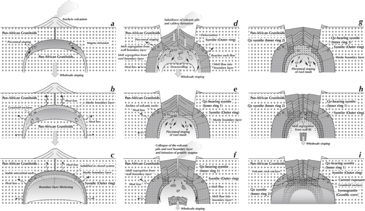
Figure 20. Schematic illustration of formation processes of the WDRC constrained in this study. See the main text for details. See also Suppl. Doc. (‘Constraints for formation model of the WDRC’ in section SUPPLEMENTARY MATERIALS FOR DISCUSSION) for the employed constraints. Qz, quartz; BL, boundary layer.
After the emplacement, the trachyte magma started to cool releasing heat to the country rock causing contact metamorphism, which is recorded in the country rock as replacement of mafic minerals by polycrystalline aggregate and formation of fine-grained veins and crystallization of clinopyroxene in the Pan-African granitoids (Fig. 20b). Through cooling from above and from the sidewall, boundary layer started to form and thickened. During the growth of the boundary layer, blocks of granitoids were entrapped in the outer ring, which are observed in the field (Fig. 5). Heat loss was more effective from above because of the shallow emplacement, and this led to the formation of a thicker roof boundary layer than sidewall boundary layer. The absence of volcanic rock blocks in the outer ring suggests that the roof boundary layer formed beneath the country rock that formed the floor to the volcanic pile.
The boundary layer thickened with time, but the outermost zone near the country rocks cooled more rapidly leading to this domain remained as a closed chemical system and keeping the initial trachyte magma composition (Fig. 20c). This emplacement environment is reflected in the fine grain size of constituent minerals (Figs. 11a and 11f) and homogeneously distributed thin ilmenite lamellae in magnetite (Figs. 10c and 10d). The inner zone of the boundary layer still contained significant amount of trapped melt forming a magma mush. Because of the lower density of fractionated melt than that of the original trachyte magma (Baker et al., 1977) the melt was stable in the roof boundary layer. Interstitial melt formed in the wall boundary layer also stayed there because the wall was sloped outward (Frisch and Abdel-Rahman, 1999) and the roof boundary layer was thicker than the wall boundary layer due to the effective heat loss to the roof, which resulted in formation of more fractionated low density interstitial melt in the roof boundary layer.
After the roof boundary layer thickened and cooled from above and volcanic products piled up on the surface, the load of the roof surpassed the pressure of the magma body leading to its collapse and a series of successive stoping events starting from the roof boundary layer, followed by the granitoid roof, and finally the volcanic pile (Fig. 20d). The stoping was initially wholesale but became piecemeal in the end when the volcanic pile collapsed. The subsidence progressed slowly along ring faults inducing deformation in the outer ring near the fault. The main ring fault was circular in the east but was more linear in the west, which caused more subsidence in the east as compared with the west, which is suggested by the morphology of the contacts of the outer ring with the inner ring 1 in the west and with the volcanic unit in the east (Figs. 3 and S1). The subsidence proceeded slowly enough to allow segregation of interstitial melt from the wall boundary layer driven by induced lower pressure in the melt. The flow from the wall boundary later in turn induced melt flow from the deeper main magma body, which inhibited compaction at the uppermost wall boundary layer to maintain the segregation. This may have given rise to reactive melt migration in the inner zone of the upper part of the wall boundary layer up to the ring fault. The segregated melt had the chemical composition of quartz-bearing syenite and ponded below the upper zone of the magma body, beneath the remained volcanic pile. The roof boundary layer may have partially, or completely disintegrated releasing fractionated interstitial melt with the chemical composition of quartz-bearing syenite, which could then modify the chemical composition of the main magma body to a more fractionated composition than the original trachyte. Forced convection induced by the collapsing roofs and the upward melt flow along the sidewall may have helped mixing the main magma body.
Some part of the fractionated melt segregated at the top of the magma body might have erupted leaving the remaining magma to crystallize (Fig. 20e). Piecemeal stoping of the volcanic rocks and boundary layer might have continued operating, the latter of which released fractionated melt mixed with the main magma body by forced convection. In the final stage, the volcanic rock blocks were entrapped in the crystallizing roof boundary layer of the quartz-bearing syenite. The deeper sidewall remained thickened, and this domain is expected to have a chemical composition between trachyte and quartz-bearing syenite. With loss of heat towards the surroundings, the interstitial melt became more fractionated reaching close to quartz syenite compositions. These processes produced the observed outer ring and inner ring 1, which were in part clearly separated by the sharply defined ring fault, but also affected by the local movement of interstitial melt resulting in a diffuse boundary.
When the weight of the volcanic pile and thickened roof boundary layer surpassed the pressure of the magma body and the strength of the rock pile, they collapsed along a ring fault located inside the previous ring fault because of decrease in the size of the magma body due to crystallization from the wall (Fig. 20f). The stoping in this second stage is on a smaller scale than the previous one but also induced melt segregation from the partially solidified wall boundary layer, and in this case the interstitial melt had quartz syenite composition. The stoping was piecemeal at least in the end of the collapse producing blocks of volcanic pile. The collapse of the volcanic pile may have stopped beneath the bottom of volcanic pile of the quartz-bearing syenite composition.
After the collapse of the central part, cooling from the roof enhanced crystallization of the magma with a quartz syenite composition which entrapped blocks of both trachyte and a composite of quartz-bearing syenite and trachyte (Frisch and Abdel-Rahman, 1999) (Fig. 20g). The magma body had the chemical composition of quartz syenite due to the fractionated melt released from the disintegrated roof boundary layer of quartz-bearing syenite composition. The magma continued crystallizing due to heat loss through the roof and walls, and the thickened boundary layer hosted interstitial melt with syenogranite composition.
At some point the weight of the volcanic pile and thickened roof boundary layer again surpassed the pressure of the magma body and the strength of the rock pile resulting in renewed collapse along a ring fault located inside the previous ring fault (Fig. 20h). The stoping was smaller in scale than the previous one but still induced the melt segregation from the partially solidified wall mush, the interstitial melt of which had syenogranite composition. The paucity of blocks of volcanics or quartz syenite suggests the stoping was wholesale and this would enhance the effective melt segregation from the wall boundary layer. The collapse did not reach the volcanic pile and stopped inside the roof boundary layer. The interstitial melt with syenogranite composition segregated towards the central collapsed space driven by low pressure caused by the sinking roof boundary layer.
With cooling from the roof, the segregated syenogranite magma was solidified to form the granitic core (Fig. 20i). The syenogranite magma did not include blocks of either volcanic rocks or quartz syenite because of the style of stoping. After the solidification of the granitic core, we suggest a small deep-seated magma body remained with a rhyolitic composition close to that of the syenogranite.
The current exposure of the WDRC is shown by the dot dashed line in Figure 20i. Because the exposure is inclined to the west with height difference of ∼ 350 m (Fig. S1; Table 1), the deepest level of the WDRC is exposed in the western outer ring, where our sampling of the outer ring was focused, and the shallowest part is exposed in the granitic core, which helps explain the high cooling rate recorded in the syenogranites.
During the evolution of the magma body, the magma residing in the central main part might have rarely intruded into the already cooled and solidified outer ring or inner rings to have crystallized there forming the outer ring intrusive and inner ring 2 intrusive members. This can explain the diverse chemical composition of the outer ring intrusive members (red stars in Fig. 17). Moreover, these intrusive rocks are porphyritic and have finer grain sizes than the host rock (Figs. S4-S6; Tables S3-S5) suggesting crystallization under higher super cooling, and thus that they were emplaced into already solidified cooler rocks of the outer ring and inner rings. Because of the decrease in horizontal size of the magma body, intrusion of magmas now forming the ring intrusive members may have taken place through fractures forming a cone sheet or radial dikes (Anderson, 1936).
Comparison with other ring complexes
Ring complexes distributed in the Eastern Desert of Egypt have common characteristics as summarized in the introduction (Tables 1 and S1). The common features allow the results of our study on the WDRC to be extended to the other ring complexes. The important features documented in the WDRC are the distribution of different lithologies in concentric ring patterns, the presence of oldest volcanic rocks closely associated with the plutonic rocks, and progressive fractionation from the outer margin to the center. Ring complexes showing such characteristics are El Gezira (El Ramly et al., 1971; Tables 1 and S1) in the Eastern Desert and the Mount Dromedary zoned monzonite pluton, southeastern Australia (Smith et al., 1988). The ∼ 99 Ma Mount Dromedary zoned monzonite pluton has an approximately oval shape in plan with a diameter of 6-7 km. It has a concentrically arranged sequence of compositionally and texturally distinct zones consisting of 1-2 km wide outer ring of mafic monzonite and syenite and a felsic core of monzonite, syenite and quartz monzonite. A crescent shape distribution of porphyritic rocks is present in the complex, which was interpreted to be a raft of pre-existing volcanic rocks. The whole-rock SiO2 content increases from 55 wt% in the margin to 65 wt% in the core. The whole-rock oxide contents plotted in Harker variation diagrams have inflexions at ∼ 60 wt% SiO2. All these features are the same as observed in the WDRC.
The magma bodies that formed the WDRC and the Mount Dromedary pluton did not have significant new magma input or crustal contamination. By contrast, the Abu Khurq ring complex in the South Eastern Desert (Tables 1 and 2) is thought to have undergone up to 20% assimilation of crustal material to derive quartz syenite, which is based on the SiO2 content and Nd isotope ratio of quartz syenite mostly sampled from the margin without gabbroic carapace (Landoll et al., 1994). Crustal assimilation was advocated by Fitton (1987) to explain the fractionation of trachytic magma to rhyolite for Cameroon line alkaline volcanism with an alternative model of fractionation of amphibole.
The contrast in involvement of crustal contamination may be attributed to the differences in magma temperature and style of convection in a hidden magma body. The Abu Khurq ring complex has gabbro along the margin (Table 2), which is absent in the WDRC, suggesting that a high-temperature basaltic magma was supplied to the magma body beneath the Abu Khurq complex. The assimilation documented in the Abu Khurq complex implies efficient heat transfer by thermal convection to the surrounding crust enhancing partial melting of the wall rocks, particularly in the earlier stage of the complex evolution (Huppert and Sparks, 1988).
CONCLUSIONS
The main conclusions of the present study on the Wadi Dib ring complex (WDRC) are as follows.
-
(1)
Field relationships between the outer ring and the volcanic unit and careful thin section observations show that the volcanic unit formed before the formation of the outer ring. The revised formation age relationship between the directly contacting volcanic and plutonic units is one of the general features of the Phanerozoic alkaline ring complexes in the Eastern Desert, suggesting subvolcanic magma emplacement related to a collapse of the overlying volcanic pile.
-
(2)
The whole rock major element concentrations of all the units show consistent trends in Harker variation diagrams with the exception of Al2O3-rich and Fe2O3-poor syenite from the outer ring. The overall trends of the plutonic unit can be reproduced by fractional crystallization starting with the trachyte without significant involvement of magma replenishment or crustal contamination.
-
(3)
Syenites from the innermost outer ring closer to the inner ring show high degrees of deformation, which gradually decrease outwards in the outer ring and abruptly decrease inwards in the inner ring 1. The highly deformed syenites are Al2O3-rich and Fe2O3-poor and show microstructures suggesting reactive melt transportation. The Al2O3-poor and Fe2O3-rich syenites have identical whole-rock chemical compositions to trachyte of the volcanic unit and are rich in amphibole enclosing anhedral clinopyroxene. The thickness of ilmenite lamellae in magnetite increases from the outer margin to the inner margin of the outer ring. These characteristics of the outer ring indicate that the outer ring was a wall boundary layer consisting of outer zone of frozen trachytic magma rapidly crystallized in a closed system and the inner zone of magma mush was affected by reactive melt transportation likely driven by collapse of the roof boundary layer and overlying volcanic pile.
-
(4)
The WDRC formed at a shallow crustal level at a depth of a few km and was evolved by progressive and efficient cooling from the surface promoting fractional crystallization of trachytic magma through strong coupling of collapse of the roof, which induced chemical fractionation and magma emplacement. Fractional crystallization of the WDRC is attributed to segregation of fractionated melt from the wall mush zone toward the complex center driven by decreasing melt pressure induced by slow collapse of the roof to fill the space formed by the collapse.
ACKNOWLEDGMENTS
We are grateful to Prof. S.R. Wallis of the University of Tokyo for his fruitful discussion and useful comments, which stimulate us to advance this study. We also appreciate his reading of the first submitted version, which greatly improved the manuscript. We thank anonymous reviewers for many comments, which significantly improved the manuscript. We thank Prof. M. Satish-Kumar for helpful advice and useful comments in his editorial handling. E.S. thank Dr. S. Hamid for his kind help in the field and Dr. Y. Sato for his kind help during stay at the University of Tokyo. We thank Mr. Yoshida for his help in EPMA, FE-SEM, and XRF analyses at the Department of the Earth and Planetary Science, the University of Tokyo and Ms. N. Hokanishi for her help in XRF analyses at the Earthquake Research Institute, the University of Tokyo. This study was supported by RONPAKU (Dissertation PhD) program of Japan Society for Promotion of Science (JSPS) ID No. R11840 carried out at the Department of Earth and Planetary Science of the University of Tokyo during FY 2018-2022 . This work was also supported by JSPS KAKENHI Grant Numbers JP20H02003 and JP23K03544 to K.O.
REFERENCES
- Abdel-Karim, A. and Arva-Sos, E. (2000) Geochemical characteristics and K-Ar ages dating of some granitoid rocks from South Eastern Desert, Egypt. Egyptian Journal of Geology, 44, 305-318.
- Abdel-Karim, A.A.M., Azer, M.K. and El-Shafei, S.A. (2021) Petrology and Geochemistry of Some Ophiolitic Metaperidotites from the Eastern Desert of Egypt: Insights into Geodynamic Evolution and Metasomatic Processes. Acta Geologica Sinica, 95, 1139-1157.
- Abu El-Leil, H.M., Azzam, M.H.B. and El-Shaheed, I.A. (2017) Geology and Geochemistry of Magmatic Rocks, Gabal Elba Area, South Eastern Desert. Egypt. Report and Opinion, 9, 9-27.
- Akaad, M.K. and El Ramly, M.F. (1962) The nepheline-syenite ring complex of Gebel Abu Khruq, South Eastern Desert of Egypt. Geological Survey of Egypt, 14, 1-22.
- Al-Damegh, K., Sandvol, E. and Barazangi, M. (2005) Crustal structure of the Arabian plate: new constraints from the analysis of teleseismic receiver functions. Earth and Planetary Science Letters, 231, 177-196.
- Anderson, E.M. (1936) The dynamics of the formation of cone-sheets, ring-dykes, and caldron-subsidences. Proceedings of the Royal Society of Edinburgh, 56, 128-163.
- Baker, B.H., Goles, G.G., Leeman, W.P. and Lindstrom, M.M. (1977) Geochemistry and petrogenesis of a basalt-benmoreite-trachyte suite from the southern part of the Gregory Rift, Kenya. Contributions to Mineralogy and Petrology, 64, 303-332.
- Bédard, J.H., Kerr, R.C. and Hallworth, M.A. (1992) Porous sidewall and sloping floor crystallization experiments using a reactive mush: implications for the self-channelization of residual melts in cumulates. Earth and Planetary Science Letters, 111, 319-329.
- Be’eri-Shlevin, Y., Katzir, Y. and Valley, J.W. (2009) Crustal evolution and recycling in a juvenile continent: Oxygen isotope ratio of zircon in the northern Arabian Nubian Shield. Lithos, 107, 169-184.
- Bowles, J.F.W. (1977) A method of tracing the temperature and oxygen-fugacity histories of complex magnetite-ilmenite grains. Mineralogical Magazine, 41, 103-109.
- Brophy, J., Dorais, M., Donnelly-Nolan, J. and Singer, B. (1996) Plagioclase zonation styles in hornblende gabbro inclusions from Little Glass Mountain, Medicine Lake Volcano, California: Implications for fractionation mechanisms and the formation of composition gaps. Contributions to Mineralogy and Petrology, 126, 121-136.
- Bryan, W.B., Finger, L.W. and Chayes, F. (1969) Estimating Proportions in Petrographic Mixing Equations by Least-Squares Approximation. Science, 163, 926-927.
- Buddington, A.F. and Lindsley, D.H. (1964) Iron-Titanium Oxide Minerals and Synthetic Equivalents. Journal of Petrology, 5, 310-357.
- Coogan, L.A., Saunders, A.D., Kempton, P.D. and Norry, M.J. (2000) Evidence from oceanic gabbros for porous melt migration within a crystal mush beneath the Mid-Atlantic Ridge. Geochemistry, Geophysics, Geosystems, 1.
- Cox, K.G., Bell, J.D. and Pankhurst, R.J. (1979) The interpretation of igneous rocks. pp.450, George Allen and Unwin, London.
- Cruden, A.R. and Weinberg, R.F. (2018) Mechanisms of Magma Transport and Storage in the Lower and Middle Crust—Magma Segregation, Ascent and Emplacement. In Volcanic and Igneous Plumbing Systems (Burchardt, S. Ed.). Elsevier, 13-53.
- Daly, R.A. (1903) The mechanics of igneous intrusion. American Journal of Science, s4-15, 269-298.
- de Gruyter, P. and Vogel, T.A. (1981) A model for the origin of the alkaline complexes of Egypt. Nature, 291, 571-574.
- Downes, H. (1987) Tertiary and Quaternary volcanism in the Massif Central, France. In Alkaline Igneous Rocks (Fitton, J.G. and Upton, B.G.J. Eds.). Geological Society Special Publication, 30, 517-530.
- Edwards, B.R. and Russell, J.K. (2000) Distribution, nature, and origin of Neogene-Quaternary magmatism in the northern Cordilleran volcanic province, Canada. Geological Society of America Bulletin, 112, 1280-1295.
- El Gaby, S., List, F.K. and Tehrani, R. (1990) The basement complex of the Eastern Desert and Sinai. In The Geology of Egypt (Said, R. Ed.). Rotterdam, Balkema, 175-184.
- EL Ramly, M.F., Budanov, V.I., Dereniuk, N.E., Armanious, L.K. and Hayek, G.G. (1969) A petrological study on the central part of Gabal Abu Khruq Ring Complex, South Eastern Desert of Egypt. The Geological Survey of Egypt, Paper No. 51, 1-53.
- El Ramly, M.F., Budanov, V.I. and Hussein, A.A. (1971) The alkaline rocks of South-Eastern Egypt. The Geological Survey of Egypt Paper No. 53, 1-111.
- El-Ramly, M.F., Hussein, A.A. and Francis, M.H. (1976) The ring complex of Wadi Dib, North Eastern Desert, Egypt. Annals of the Geological Survey of Egypt, 12, 1-6.
- El Ramly, M.F. and Hussein, A.A. (1982) The alkaline ring complexes of Egypt. Geological Survey of Egypt, Paper No. 63, 1-16.
- El Ramly, M.F. and Hussein, A.A. (1985) The ring complexes of the Eastern Desert of Egypt. Journal of African Earth Sciences, 3, 77-82.
- Fitton, J.G. (1987) The Cameroon line, West Africa: a comparison between oceanic and continental alkaline volcanism. In Alkaline Igneous Rocks (Fitton, J.G. and Upton, B.G.J. Eds.). Geological Society Special Publication, 30, 273-291.
- Francis, M.H. (1972) Geology of the basement complex in the north Eastern Desert between latitudes 27° 3′′ and 28° 0′′ N. Annals Geological Survey of Egypt, 2, 161-180.
- Frisch, W. (1982) The Wadi Dib ring complex, Nubian Desert (Egypt) and its importance for the upper limit of the Pan-African orogeny. Precambrian Research, 16, Conference abstract, A20.
- Frisch, W. and Abdel-Rahman, A.M. (1999) Petrogenesis of the Wadi Dib alkaline ring complex, Eastern Desert of Egypt. Mineralogy and Petrology, 65, 249-275.
- Geshi, N., Shimano, T., Chiba, T. and Nakada, S. (2002) Caldera collapse during the 2000 eruption of Miyakejima Volcano, Japan. Bulletin of Volcanology, 64, 55-68.
- Ghanem, M., Dardir, A.A., Francis, M.H., Zalata, A.A. and Abu Zeid, K.M. (1973) Geology of Basement rocks in Eastern Desert of Egypt North of latitudes 26° 4′′ N. Annals Geological Survey of Egypt, 3, 161-180.
- Ghazaly, M. and Sinha, A. (2002) Geochemistry and petrogenesis of anorogenic A-type granites of Um Risha and Hadayib complexes, southeastern Desert, Egypt. Egyptian Journal of Geology, 46, 55-72.
- Ghiorso, M.S. and Gualda, G.A.R. (2015) An H2O-CO2 mixed fluid saturation model compatible with rhyolite-MELTS. Contributions to Mineralogy and Petrology, 169, 53.
- Gualda, G.A.R., Ghiorso, M.S., Lemons, R.V. and Carley, T.L. (2012) Rhyolite-MELTS: a Modified Calibration of MELTS Optimized for Silica-rich, Fluid-bearing Magmatic Systems. Journal of Petrology, 53, 875-890.
- Hammond, P.A. and Taylor, L.A. (1982) The ilmenite/titano-magnetite assemblage: kinetics of re-equilibration. Earth and Planetary Science Letters, 61, 143-150.
- Hansen, S.E., Rodgers, A.J., Schwartz, S.Y. and Al-Amri, A.M.S. (2007) Imaging ruptured lithosphere beneath the Red Sea and Arabian Peninsula. Earth and Planetary Science Letters, 259, 256-265.
- Hashad, A. and El Reedy, M.W. (1979) Geochronology of the Anorogenic Alkaline Rocks, South Eastern Desert, Egypt. Annals of the Geological Survey of Egypt, 9, 81-101.
- Holness, M.B., Cheadle, M.J. and Mckenzie, D. (2005) On the use of changes in dihedral angle to decode late-stage textural evolution in cumulates. Journal of Petrology, 46, 1565-1583.
- Holness, M.B., Cesare, B. and Sawyer, E.W. (2011) Melted rocks under the microscope: microstructures and their interpretation. Elements, 7, 247-252.
- Hosny, A. and Nyblade, A. (2016) The crustal structure of Egypt and the northern Red Sea region. Tectonophysics, 687, 257-267.
- Huppert, H.E. and Sparks, R.S.J. (1984) Double-diffusive convection due to crystallization in magmas. Annual Review of Earth and Planetary Sciences, 12, 11-37.
- Huppert, H.E. and Sparks, R.S.J. (1988) The generation of granitic magmas by intrusion of basalt into continental crust. Journal of Petrology, 29, 599-624.
- Huppert, H.E. and Turner, J.S. (1991) Comments on ‘On Convective Style and Vigor in Sheet-like Magma Chambers’ by Bruce D. Marsh. Journal of Petrology, 32, 851-854.
- Katzir, Y., Eyal, M., Litvinovsky, B.A., Jahn, B.M., et al (2007) Petrogenesis of A-type granites and origin of vertical zoning in the Katharina pluton, Gebel Mussa (Mt. Moses) area, Sinai, Egypt. Lithos, 95, 208-228.
- Koide, H. and Bhattacharji, S. (1975) Mechanistic Interpretation of Rift Valley Formation. Science, 189, 791-793.
- Komuro, H. (1987) Experiments on cauldron formation: a polygonal cauldron and ring fractures. Journal of Volcanology and Geothermal Research, 31, 139-149.
- Kuritani, T. (1998) Boundary Layer Crystallization in a Basaltic Magma Chamber: Evidence from Rishiri Volcano, Northern Japan. Journal of Petrology, 39, 1619-1640.
- Kuritani, T. (1999a) Boundary layer fractionation constrained by differential information from the Kutsugata lava flow, Rishiri volcano, Japan. Journal of Geophysical Research: Solid Earth, 104, 29401-29417.
- Kuritani, T. (1999b) Thermal and compositional evolution of a cooling magma chamber by boundary layer fractionation: model and its application for primary magma estimation. Geophysical Research Letters, 26, 2029-2032.
- Kuritani, T. (2004) Magmatic differentiation examined with a numerical model considering multicomponent thermodynamics and momentum, energy and species transport. Lithos, 74, 117-130.
- Landi, P., Bertagnini, A. and Rosi, M. (1999) Chemical zoning and crystallization mechanisms in the magma chamber of the Pomici di Base plinian eruption of Somma-Vesuvius (Italy). Contributions to Mineralogy and Petrology, 135, 179-197.
- Landoll, J.D., Foland, K.A. and Henderson, C.M.B. (1994) Nd isotopes demonstrate the role of contamination in the formation of coexisting quartz and nepheline syenites at the Abu Khruq Complex, Egypt. Contributions to Mineralogy and Petrology, 117, 305-329.
- Langmuir, C.H. (1989) Geochemical consequences of in situ crystallization. Nature, 340, 199-205.
- Le Bas, M.J., Maitre, R.W.L., Streckeisen, A., Zanettin, B., et al (1986) A chemical classification of volcanic rocks based on the total alkali-silica diagram. Journal of Petrology, 27, 745-750.
- Liégeois, J.P. and Black, R. (1987) Alkaline magmatism subsequent to collision in the Pan-African belt of the Adrar des Iforas (Mali). In Alkaline Igneous Rocks (Fitton, J.G. and Upton, B.G.J. Eds.). Geological Society Special Publication, 30, 381-401.
- Lofgren, G. (1980) Experimental studies on the dynamic crystallization of silicate melts. In Physics of Magmatic Processes (Hargraves, R.B. Ed.). Princeton University Press, Princeton, 487-551.
- Lutz, T.M. (1979) Strontium and Oxygen isotope relations and geochemistry of the Abu Khruq complex, Egypt. Contributions in Mineralogy and Petrology, 98, 212-223.
- Lutz, T.M., Foland, K.A., Faul, H. and Srogi, L. (1988) The strontium and oxygen isotopic record of hydrothermal alteration of syenites from the Abu Khruq complex, Egypt. Contributions to Mineralogy and Petrology, 98, 212-223.
- Marsh, B.D. (1989) Magma chambers. Annual Review in Earth and Planetary Science, 17, 439-472.
- Marsh, B.D. (1996) Solidification fronts and magmatic evolution. Mineralogical Magazine, 60, 5-40.
- Mooney, W.D., Gettings, M.E., Blank, H.R. and Healy, J.H. (1985) Saudi Arabian seismic-refraction profile: A travel time interpretation of crustal and upper mantle structure. Tectonophysics, 111, 173-246.
- Moreno, J.A., Montero, P., Abu Anbar, M., Molina, J.F., et al (2012) SHRIMP U-Pb zircon dating of the Katerina Ring Complex: insights into the temporal sequence of Ediacaran calc-alkaline to peralkaline magmatism in southern Sinai, Egypt. Gondwana Research, 21, 887-900.
- Morgan, P., Boulos, F.K., Hennin, S.F., El-Sherif, A.A., et al (1985) Heat flow in Eastern Egypt: The thermal signature of a continental breakup. Journal of Geodynamics, 4, 107-131.
- Nielsen, R.L. and DeLong, S.E. (1992) A numerical approach to boundary layer fractionation: application to differentiation in natural magma systems. Contributions to Mineralogy and Petrology, 110, 355-369.
- O’Hara, M.J. and Fry, N. (1996) Geochemical Effects of Small Packet Crystallization in Large Magma Chambers—Further Resolution of the Highly Compatible Element Paradox. Journal of Petrology, 37, 891-925.
- Omar, G.I., Kohn, B.P., Lutz, T.M. and Faul, H. (1987) The cooling history of Silurian to Cretaceous alkaline ring complexes, south Eastern Desert, Egypt, as revealed by fission-track analysis. Earth and Planetary Science Letters, 83, 94-108.
- Parsons, I. and Brown, W.L. (1991) Mechanisms and Kinetics of Exsolution —Structural Control of Diffusion and Phase Behavior in Alkali Feldspars Alkali Feldspars. In Diffusion, Atomic Ordering, and Mass Transport (Ganguly, J. Ed.). Advances in Physical Geochemistry, 8. Springer, New York, 304-344.
- Propach, G. (1976) Models of filter differentiation. Lithos, 9, 203-209.
- Rolandone, F., Lucazeau, F., Leroy, S., Mareschal, J.C., et al (2013) New heat flow measurements in Oman and the thermal state of the Arabian Shield and Platform. Tectonophysics, 589, 77-89.
- Ryan, M.P. (1993) Neutral buoyancy and the structure of mid-ocean ridge magma reservoirs. Journal of Geophysical Research: Solid Earth, 98, 22321-22338.
- Sanfilippo, A., MacLeod, C.J., Tribuzio, R., Lissenberg, C.J. and Zanetti, A. (2020) Early-Stage Melt-Rock Reaction in a Cooling Crystal Mush Beneath a Slow-Spreading Mid-Ocean Ridge (IODP Hole U1473A, Atlantis Bank, Southwest Indian Ridge). Frontiers in Earth Science, 8, 579138.
- Serencsits, C.M., Faul, H., Foland, K.A., EL Ramly, M.F. and Hussein, A.A. (1979) Alkaline ring complexes in Egypt, their ages and relationship to tectonic development of Red Sea. Annals of the Geological Survey of Egypt, 9, 102-116.
- Serencsits, C.M., Faul, H., Foland, K.A., Hussein, A.A. and Lutz, T.M. (1981) Alkaline ring complexes in Egypt: Their ages and relationship in time. Journal of Geophysical Research: Solid Earth, 86, 3009-3013.
- Sibbett, B.S. (1988) Size, depth and related structures of intrusions under stratovolcanoes and associated geothermal systems. Earth Science Reviews, 25, 291-309.
- Simura, R. and Ozawa, K. (2011) Magmatic Fractionation by Compositional Convection in a Sheet-like Magma Body: Constraints from the Nosappumisaki Intrusion, Northern Japan. Journal of Petrology, 52, 1887-1925.
- Smith, I.E.M., White, A.J.R., Chappell, B.W. and Eggleton, R.A. (1988) Fractionation in a zoned monzonite pluton: Mount Dromedary, southeastern Australia. Geological Magazine, 125, 273-284.
- Smith, P. and Parsons, I. (1974) The alkali-feldspar solvus at 1 kilobar water-vapor pressure. Mineralogical Magazine, 39, 747-767.
- Sobh, M., Ebbing, J., Mansi, A.H. and Götze, H.J. (2019) Inverse and 3D forward gravity modelling for the estimation of the crustal thickness of Egypt. Tectonophysics, 752, 52-67.
- Sparks, R.S.J., Huppert, H.E. and Turner, J.S. (1984) The fluid dynamics of evolving magma chambers. Philosophical Transactions of the Royal Society of London. Series A, Mathematical and Physical Sciences, 310, 511-534.
- Speciale, P.A., Tokle, L. and Behr, W.M. (2022) Feldspar and orthopyroxene piezometers constrained using quartz-feldspar and olivine-orthopyroxene mineral pairs from natural mylonites. Journal of Structural Geology, 154, 104495.
- Stern, R.J. (2018) Neoproterozoic formation and evolution of Eastern Desert continental crust - The importance of the infrastructure-superstructure transition. Journal of African Earth Sciences, 146, 15-27.
- Stern, R.J. and Hedge, C.E. (1985) Geochronologic and isotopic constraints on late Precambrian crustal evolution in the Eastern Desert of Egypt. American Journal of Science, 285, 97-127.
- Stern, R.J. and Johnson, P. (2010) Continental lithosphere of the Arabian Plate: A geologic, petrologic, and geophysical synthesis. Earth Science Reviews, 101, 29-67.
- Streckeisen, A.L. (1974) Classification and nomenclature of plutonic rocks recommendations of the IUGS subcommission on the systematics of Igneous Rocks. Geologische Rundschau, 63, 773-786.
- Tait, S. and Jaupart, C. (1989) Compositional convection in viscous melts. Nature, 338, 571-574.
- Tait, S., Jahrling, K. and Jaupart, C. (1992) The planform of compositional convection and chimney formation in a mushy layer. Nature, 359, 406-408.
- Tait, S. and Jaupart, C. (1992) Compositional convection in a reactive crystalline mush and melt differentiation. Journal of Geophysical Research: Solid Earth, 97, 6735-6756.
- Tait, S.R. (1988) Samples from the crystallizing boundary layer of a zoned magma chamber. Contributions to Mineralogy and Petrology, 100, 470-483.
- Tang, Z., Julià, J., Zahran, H.M. and Mai, P.M. (2016) The lithospheric shear-wave velocity structure of Saudi Arabia: Young volcanism in an old shield. Tectonophysics, 680, 8-27.
- Upton, B.G.J. and Emeleus, C.H. (1987) Mid-Proterozoic alkaline magmatism in southern Greenland: the Gardar province. In Alkaline Igneous Rocks (Fitton, J.G. and Upton, B.G.J. Eds.). Geological Society Special Publication, 30, 449-471.
- Vail, J.R. (1989) Ring Complexes and Related Rocks in Africa. Journal of African Earth Sciences, 8, 19-40.
- Wilson, M. (1989) Igneous Petrogenesis. pp.466, Unwin Hyman, London.
- Woolley, A.R. and Jones, G.C. (1987) The petrochemistry of the northern part of the Chilwa alkaline province, Malawi. In Alkaline Igneous Rocks (Fitton, J.G. and Upton, B.G.J. Eds.). Geological Society Special Publication, 30, 335-355.
- Yao, Z., Mooney, W.D., Zahran, H.M. and Youssef, S.E. (2017) Upper mantle velocity structure beneath the Arabian shield from Rayleigh surface wave tomography and its implications. Journal of Geophysical Research: Solid Earth, 122, 6552-6568.
- Žák, J., Holub, F. and Kachlík, V. (2006) Magmatic stoping as an important emplacement mechanism of Variscan plutons: Evidence from roof pendants in the Central Bohemian Plutonic Complex (Bohemian Massif). International Journal of Earth Sciences, 95, 771-789.
