Abstract
The intensity tensor for Fe2+ doublets at the M2 sites and electric field gradient tensor for Fe2+ at the M2 sites in two enstatites (En) with the orthorhombic system were determined by single crystal Mössbauer spectroscopy to examine the ferrosilite (Fs) component dependence of the intensity tensor of enstatite. The components of the intensity tensor for Fe2+ doublets at the M2 sites in the En65.5Fs31.7Wo2.7-enstatite and En90.7Fs8.7Wo0.6-enstatite are IXX = 0.577(6), IYY = 0.454(6), and IZZ = 0.470(12), and 0.616(2), 0.458(4), and 0.426(6), respectively. Thus, those three components have a weak dependence on the contents of Fs component. The components, IXY, IYZ, and IXZ, of the intensity tensor due to Mössbauer nuclei that occupy general positions in the space group Pbca pyroxene structure are derived as IXY = IYZ = IXZ = 0 by the symmetric summation of equivalent Mössbauer nuclei in the structural site. Three components, IXX, IYY, and IZZ, were determined by applying constraint of IXY = IYZ = IXZ = 0. The intensity tensors by Mössbauer nuclei at general positions obtained without any constraints (IXY ≠ IYZ ≠ IXZ ≠ 0) are consistent with those derived by applying the symmetrical constraint (IXY = IYZ = IXZ = 0). This indicates that the intensity tensor due to Mössbauer nuclei that occupy general positions can be simplified by the symmetrical constraint.
INTRODUCTION
Fe compositional dependence of intensity tensor of Mössbauer doublet for Fe2+ in pyroxene
Pyroxenes are chain silicates with structural formula (M2)(M1)(Si, Al)2O6 (Deer et al., 1978). In Ca-Mg-Fe clinopyroxenes, the M1 sites are almost regular octahedral sites, and the M2 sites are larger and distorted 8-coordination sites. Fe2+ ions occupy both M1 and M2 sites. In the orthopyroxenes, the M1 sites are also almost regular octahedral sites, and the M2 sites are distorted 6-coordination sites (Sueno et al., 1976). Fe2+ ions prefer the M2 sites in the orthopyroxene (e.g., Virgo and Hafner, 1969). 57Fe Mössbauer spectroscopy is an important and unique method that can measure the occupancies of Fe2+ and Fe3+ in these sites in pyroxene minerals. Fe2+ ions at the M sites show doublets due to quadrupole splitting in Mössbauer spectra.
In the Mössbauer spectrum measured for a powder sample, the peak of the higher and lower Doppler velocity components that construct a doublet are generally the same as each other (Bancroft et al., 1968: and others). In contrast, a doublet in a Mössbauer spectrum measured for a single crystal consists of higher and lower Doppler velocity components with different intensities from each other (i.e., the peak intensity ratio is not always 1:1) (Zimmermann, 1975; Tennant et al., 2000; Shinoda and Kobayashi, 2019; Fukuyama et al., 2022). The peak intensity ratio of the doublet in a single crystal Mössbauer spectrum is dependent on the direction of incident γ-rays with respect to the crystallographic axes of the single crystal. Zimmermann (1975) proposed theoretical and experimental methods to calculate the peak intensity ratio of the doublet in a single crystal Mössbauer spectrum by using a tensor and indicated that ‘it is favourable to consider reduced intensities (i.e., intensity of one quadrupole line divided by the total intensity) instead of intensity ratios’. According to Zimmermann (1975), reduced intensity (I) is defined as follows:
| \begin{equation}
I = \frac{I^{\text{h}}}{I^{\text{h}} + I^{\text{l}}}
\end{equation}
| (1). |
The reduced intensity (I) is the intensity of the higher Doppler velocity component (Ih) normalized by the total of the intensity (Ih + Il) of the higher and lower Doppler velocity components (Il). The reduced intensity (I) is calculated from an ‘intensity tensor’ (Zimmermann, 1975). A doublet of the single crystal Mössbauer spectrum is characterized by four parameters, the isomer shift (δ), quadrupole splitting (Δ), line width (Γ), and reduced intensity (I).
In pyroxene minerals, Fe ions show doublets with slightly different Mössbauer parameters depending on M sites. In hedenbergite-ferrosilite pyroxenes, a distinct doublet arises from each of the four different types of next-nearest-neighbor configurations for Fe cations in the M1 sites by Dowty and Lindsley (1973). Thus, raw data of Mössbauer spectra of pyroxene minerals can include overlapping a few doublets. If intensities of a few doublets are known for a given thin section, fourth parameters (I) of those doublets can be fixed for resolving a doublet to component peaks. Thus, the reduced intensity (I) is an important parameter for the single crystal Mössbauer spectroscopic analysis of pyroxene in a thin section. The significance to determine the intensity tensor and its compositional dependence were emphasized by Fukuyama et al. (2022). According to Fukuyama et al. (2022), the intensity tensors of doublets in Mössbauer spectra due to Fe2+ at the M1 sites of Ca-Mg-Fe clinopyroxenes, such as diopside, hedenbergite, and augite are dependent on the Wo content, but independent on the Fs content. Thus, if Wo contents in Ca-Mg-Fe clinopyroxenes are not variable, the components of the intensity tensor for Fe2+ are supposed to be almost constant. However, this tendency has not been examined in pyroxene group minerals except for Ca-Mg-Fe clinopyroxenes with Wo50 (Fukuyama et al., 2022). Compositional dependences of the intensity tensor for Fe2+ ions at M1 and M2 sites are unknown for Ca-Mg-Fe clinopyroxenes with low Wo content, clinopyroxene of space group P21/c and orthopyroxenes. Among the remaining problems on compositional dependences of intensity tensors, the intensity tensors for Fe2+ at the M2 sites of orthopyroxene with the space group Pbca were determined from Mössbauer spectra of single crystals of two enstatites with different Fs contents to examine the Fs-dependence of the intensity tensor of orthopyroxenes in this study. Single crystals of Fe-rich and Fe-poor enstatites were used for this study. X-ray diffraction analysis with a precession camera was performed to adjust crystallographic orientations for both samples. Mössbauer spectra of the oriented thin sections were measured for two enstatites to obtain the intensity tensors for quadrupole doublets.
The M2 and M1 sites in clinopyroxenes with the space group C2/c occupy special positions on a diad axis along the crystallographic b axis (Cameron and Papike, 1980). Shinoda and Kobayashi (2019) derived numerical constraints on the tensor components from a symmetrical consideration, where XZ (= ZX) and YZ (= ZY) components of the intensity tensor and electric field gradient (EFG) tensor due to Fe ions at the M sites of the special position can be set to zero. In enstatites, the M2 and M1 sites are located at the general positions in the space group Pbca structure (Cameron and Papike, 1980). This suggests that all components of the intensity and EFG tensors cannot be simply set to zero. In this study, components of the intensity and EFG tensors due to Mössbauer nuclei at the general positions in the space group Pbca structure are derivated from a symmetrical consideration and it can be demonstrated that the intensity tensor can be simplified, and that experimentally determined intensity tensors by applying symmetrical constraints are consistent with tensors derived without any symmetrical constraints.
Tensors of intensity of quadrupole doublets and electric field gradient for the M2 and M1 sites in orthopyroxene
According to Zimmermann (1983), the reduced intensity (I) of quadrupole doublets can be calculated from Eq. (2) by setting a rectangular coordinate in a crystallographic axis as
| \begin{equation}
I(\theta ,\phi) =
\begin{pmatrix}
e_{X} & e_{Y} & e_{Z}
\end{pmatrix}
\boldsymbol{I}
\begin{pmatrix}
e_{X} \\
e_{Y} \\
e_{Z}
\end{pmatrix}
\end{equation}
| (2), |
where I is the intensity tensor:
| \begin{equation}
\boldsymbol{I} =
\begin{pmatrix}
I_{XX} & I_{XY} & I_{XZ} \\
I_{XY} & I_{YY} & I_{YZ} \\
I_{XZ} & I_{YZ} & I_{ZZ}
\end{pmatrix}
\end{equation}
| (3). |
The angles θ and ϕ in Eq. (2) are the polar angles for the rectangular coordinates of the incident γ-rays, I(θ, ϕ) is the reduced intensity, and eX (= sinθ cosϕ), eY (= sinθ sinϕ), and eZ (= cosθ) are the direction cosines of the incident γ-rays.
A quadrupole doublet originates in the EFG caused by a point charge q out of a Mössbauer nucleus. By setting the position of the Mössbauer nucleus at (a, b, c) and the position of the point charge at (a + x, b + y, c + z), the components (Vij) of the EFG tensor V due to q are represented as follows:
| \begin{equation}
V_{ij} = -q(3x_{i}x_{j} - r^{2}\delta_{ij})/r^{5}
\end{equation}
| (4), |
where i, j = 1-3, x1 = x, x2 = y, x3 = z, r = (x2 + y2 + z2)(1/2), δij = 0 if i ≠ j, and δij = 1 if i = j (modified from Travis, 1971).
Since the Mössbauer nuclei in orthopyroxene are located at the M2 and M1 sites which are in general positions, there are no symmetrically related atoms out of the Mössbauer nuclei. Therefore, all EFG components Vij for a Mössbauer nucleus cannot be set to zero. However, some EFG tensor components for Mössbauer nuclei in the space group Pbca orthopyroxene must be constrained to zero because there are equivalent positions in the structure and the EFG tensors given by the summation of EFG components are simplified as follows.
There are eight general positions per unit cell in the Pbca orthopyroxene structure, which are noted by [1]-[8] notations in this paper as follows:
| \begin{equation}
\left.
\begin{matrix}
[1](a, b,c), [2]\left(\bar{a} + \cfrac{1}{2}, \bar{b}, c + \cfrac{1}{2}\right)\\
[3]\left(\bar{a}, b + \cfrac{1}{2}, \bar{c} + \cfrac{1}{2}\right), [4]\left(a + \cfrac{1}{2}, \bar{b} + \cfrac{1}{2}, \bar{c}\right) \\
[5](\bar{a}, \bar{b},\bar{c}), [6]\left(a + \cfrac{1}{2},b, \bar{c} + \cfrac{1}{2}\right) \\
[7]\left(a, \bar{b} + \cfrac{1}{2}, c + \cfrac{1}{2}\right), [8]\left(\bar{a} + \cfrac{1}{2}, b + \cfrac{1}{2}, c\right)
\end{matrix}
\right\}
\end{equation}
| (5). |
Therefore, the Mössbauer nuclei at the M2 and M1 sites are assumed to occupy the eight general positions of [1]-[8] in Eq. (5). Supposing a Mössbauer nucleus at the general position [1] at (a, b, c) and a point charge q[1], that causes quadrupole splitting for nucleus [1], at (a + x, b + y, c + z), components (Vij[1]) of the EFG tensor V[1] due to q[1] are represented as follows:
| \begin{equation}
V_{ij}^{[1]} = -q^{[1]}(3x_{i}x_{j} - r^{2}\delta_{ij})/r^{5}
\end{equation}
| (6). |
The full representations for Vij are as follows:
| \begin{equation}
\left.
\begin{matrix}
V_{xx}^{[1]} = -q(3x^{2} - r^{2})/r^{5},\ \\
V_{yy}^{[1]} = -q(3y^{2} - r^{2})/r^{5},\ \\
V_{zz}^{[1]} = -q(3z^{2} - r^{2})/r^{5} \\
V_{xy}^{[1]} = V_{yx}^{[1]} = -3qxy/r^{5},\ \\
V_{yz}^{[1]} = V_{zy}^{[1]} = -3qyz/r^{5},\ \\
V_{xz}^{[1]} = V_{zx}^{[1]} = -3qxz/r^{5}
\end{matrix}
\right\}
\end{equation}
| (7). |
From [2] of Eq. (5), a Mössbauer nucleus at the general position [2] and the point charge q[2], which are equivalent to Mössbauer nucleus at the general position [1] and the point charge q[1], are located at (−a + 1/2, −b, c + 1/2) and (−(a + x) + 1/2, −(b + y), (c + z) + 1/2), respectively. This is an equivalent arrangement where the Mössbauer nucleus at the general position [2] and the point charge q[2] are located at (0, 0, 0) and (−x, −y, z), respectively. Thus, the components (Vij[2]) of the EFG tensor V[2] due to q[2] are
| \begin{equation}
\left.
\begin{matrix}
V_{xx}^{[2]} = V_{xx}^{[1]}, V_{yy}^{[2]} = V_{yy}^{[1]}, V_{zz}^{[2]} = V_{zz}^{[1]}, \\
V_{xy}^{[2]}(= V_{yx}^{[2]}) = V_{xy}^{[1]}(= V_{xy}^{[1]}) \\
V_{yz}^{[2]}(= V_{zy}^{[2]}) = -V_{yz}^{[1]}(= -V_{zy}^{[1]}), \\
V_{xz}^{[2]}(= V_{zx}^{[2]}) = -V_{xz}^{[1]} = (= -V_{zx}^{[1]})
\end{matrix}
\right\}
\end{equation}
| (8). |
In the same way, the equivalent point charges of q[3] to q[8] for the equivalent Mössbauer nucleus of [3]-[8] assumed at (0, 0, 0) are located at
| \begin{align}
&q^{[3]}{:}\, (\bar{x}, y, \bar{z}), q^{[4]}{:}\, (x, \bar{y}, \bar{z}), q^{[5]}{:}\, (\bar{x}, \bar{y}, \bar{z}),\\&q^{[6]}{:}\, (x, y, \bar{z}), q^{[7]}{:}\, (x, \bar{y}, z), q^{[8]}{:}\, (\bar{x}, y, z)
\end{align}
| (9). |
Calculating Vij[3]-[8] from Eq. (9) and summing the EFG components due to point charges [1]-[8] result in
| \begin{equation}
\sum_{n=1}^{8}V_{ij}^{[n]} \ne 0; (i = j), \sum_{n = 1}^{8}V_{ij}^{[n]} = 0; (i \ne j)
\end{equation}
| (10). |
Therefore, the EFG tensor for the M2 and M1 sites of orthopyroxene can be assumed to a diagonal tensor:
| \begin{equation}
\begin{pmatrix}
\text{V}_{\text{XX}} & 0 & 0 \\
0 & \text{V}_{\text{YY}} & 0 \\
0 & 0 & \text{V}_{\text{ZZ}}
\end{pmatrix}
\end{equation}
| (11), |
where the trace is zero (VXX + VYY + VZZ = 0). V in normal font is the traceless intensity tensor for the diagonal matrix. The intensity tensor components Iij is related to the EFG tensor components Vij as follows:
| \begin{equation}
I_{ij} = \frac{1}{2}\delta_{ij} \pm \frac{eQ}{8|\Delta E_{Q}|}V_{ij}
\end{equation}
| (12), |
where e is the positive elementary charge, Q is the nuclear quadrupole moment, and ΔEQ is the quadrupole splitting. The positive and negative terms apply to higher and lower Doppler velocity components, respectively (Zimmermann, 1975). From Eqs. (3), (11), and (12), the intensity tensor I for the M sites in orthopyroxene can be expressed as
| \begin{equation}
\mathbf{I} =
\begin{pmatrix}
\mathrm{I}_{\text{XX}} & 0 & 0 \\
0 & \mathrm{I}_{\text{YY}} & 0 \\
0 & 0 & \mathrm{I}_{\text{ZZ}}
\end{pmatrix}
\end{equation}
| (13), |
where IXX + IYY + IZZ = 3/2. Eq. (13) is derived from the symmetrical constraint. I in normal font is for the diagonal matrix. The reduced intensity for a single crystal of orthopyroxene can be expressed as
| \begin{equation}
I(\theta ,\phi) =
\begin{pmatrix}
e_{X} & e_{Y} & e_{Z}
\end{pmatrix}
\begin{pmatrix}
\mathrm{I}_{\text{XX}} & 0 & 0 \\
0 & \mathrm{I}_{\text{YY}} & 0 \\
0 & 0 & \mathrm{I}_{\text{ZZ}}
\end{pmatrix}
\begin{pmatrix}
e_{X} \\
e_{Y} \\
e_{Z}
\end{pmatrix}
\end{equation}
| (14). |
The intensity tensor can be experimentally determined by the measurement of Mössbauer spectra of crystallographically oriented thin sections with various directions of the γ-rays against the crystallographic axes and application of least-squares fitting (LSQ) to the reduced intensities and γ-ray directions. From Eq. (14), the observation equation for the LSQ is given as
| \begin{align}
&{(\sin^{2}\theta_{i}\cos^{2}\phi_{i} - \cos^{2}\theta_{i})\mathrm{I}_{\text{XX}} + (\sin^{2}\theta_{i}\sin^{2}\phi_{i} - \cos^{2}\theta_{i})\mathrm{I}_{\text{YY}}} \\&\quad{= I_{i}^{h}(\theta_{i}, \phi_{i}) - \frac{3}{2}\cos^{2}\theta_{i}}
\end{align}
| (15), |
where I is the number of measurements, and θi and ϕi are the angles of γ-rays for the i-th measurement. An intensity tensor Iij can be obtained by solving the simultaneous equations derived from Eq. (15).
The traceless intensity tensor T is derived as Tij = Iij − (1/2)δij from Eq. (12) for the higher Doppler velocity component, so that T is proportional to the EFG tensor:
| \begin{equation}
T_{ij} = \frac{eQ}{8|\Delta E_{Q}|}V_{ij}
\end{equation}
| (16). |
The traceless tensor T′ij = Iij − (1/2)δij can be obtained from the experimentally determined Iij.
According to Zimmermann (1975), the components of the traceless intensity tensor T must be scaled:
| \begin{align}
I_{\Delta} &= 16\bigg\{T_{ZZ}^{2} + \frac{1}{3}(T_{XX} - T_{YY})^{2} + \frac{4}{3}(T_{XY}^{2} + T_{XZ}^{2} + T_{YZ}^{2}) \bigg\} \\&= 1
\end{align}
| (17). |
T′ij is not a scaled traceless tensor; therefore, T′ij must be scaled using
| \begin{align}
I'{}_{\Delta} &= 16\bigg\{T'{}_{ZZ}^{2} + \frac{1}{3}(T'{}_{XX} - T'{}_{YY})^{2} \\&\quad+ \frac{4}{3}(T'{}_{XY}^{2} + T'{}_{XZ}^{2} + T'{}_{YZ}^{2}) \bigg\}
\end{align}
| (18) |
as follows:
| \begin{equation}
T_{ij} = \sqrt{1/I'{}_{\Delta}} T'{}_{ij}
\end{equation}
| (19). |
In the orthorhombic system, T′XY, T′XZ, and T′YZ must be zero, and T is proportional to V [Eq. (16)]. The selection of VXX, VYY, and VZZ as |VXX| < |VYY| < |VXX| provides the asymmetric parameter η as η = (VXX − VYY)/VZZ. QS (ΔEQ) in SI units is expressed as
| \begin{equation}
\Delta E_{Q} = \frac{1}{2}eQ\frac{V_{ZZ}}{4\pi \varepsilon_{0}}\sqrt{1 + \frac{1}{3}\eta^{2}}
\end{equation}
| (20), |
so that the EFG components [VXX, VYY, and VZZ (C/m3)] can be calculated using a QS of 1 mm/s = 4.80 × 10⁻⁸ eV = 7.69 × 10⁻²⁷ J, e = 1.602 × 10⁻¹⁹ C: positive elementary charge, Q = 0.16 barn (1 barn = 10−28 m2) (Dufek et al., 1995), ε0 = 8.854 × 10⁻¹² F/m, the permittivity in vacuum, and the experimentally determined η (asymmetric parameter) and ΔEQ (mm/s).
EXPERIMENTAL
Single crystals of enstatite (1) as small as 1 mm3 from Inawashiro, Aizuwakamatsu, Fukushima Prefecture, Japan and enstatite (2) from Turiani, Morogoro, Tanzania were used for this study. Three crystallographically oriented thin sections perpendicular to a*, b*, and c* were prepared for X-ray diffraction measurements using a precession camera and a Mo X-ray tube operated at 35 kV and 15 mA for both samples. Figure 1 shows a precession photograph of enstatite (2) perpendicular to the b* axis with the c* axis adjusted to the horizontal dial axis of the X-ray precession camera. The distance between the crystal and X-ray film was 60 mm. The width and height of the X-ray film were 100 and 100 mm, and the X-ray exposure time was 4 h. Seven Mössbauer spectra of the oriented thin sections were measured for enstatite (1) and twelve for enstatite (2). The Cartesian coordinates (X Y Z) are expressed as X // c*, Y // a*, Z // b*, where a*, b*, c* are the reciprocal lattice vectors for orthopyroxene.

Figure 1. X-ray Precession photo of enstatite (2) using a Mo X-ray tube. Detailed exposure conditions are shown in the text.
The chemical compositions of the enstatites were measured using scanning electron microscopy (SEM) with energy dispersive X-ray spectroscopy (EDS) at 20 kV and 500 pA. All backscattered electron images of the two samples indicate that the enstatite single crystals are homogeneous.
Mössbauer spectra were measured in transmission mode on a constant-acceleration spectrometer with a Si-PIN semiconductor detector (XR-100CR, AMPTEK Inc.) and a 1024-channel multichannel analyzer. The γ-ray source was 3.7 GBq 57Co/Rh with a diameter of 4 mm. A 57Fe-enriched iron foil was used for the velocity calibration. The two symmetric spectra were folded, and the velocity range was ±4 mm/s. The MossWinn program was used for peak separation (MossWinn, 2018).
RESULTS AND DISCUSSION
Chemical composition and Mössbauer spectroscopic analyses
Chemical compositions of two enstatites are shown in Table 1, where the weight percentage (wt%) values for oxides are averages of ten measurement points, and the estimated errors are given in parentheses. The chemical formulae of enstatites (1) and enstatite (2) are calculated as (Ca0.05Fe0.60Mg1.25Mn0.06Al0.03)Σ1.99(Si1.97Al0.03)Σ2.00O6 and (Ca0.01Fe0.17Mg1.79Al0.01)Σ1.98Si2.00O6, respectively, where the total Al content is divided into octahedral and tetrahedral sites, so that the total number of cations at tetrahedral sites is two. End member components of the former and latter are En65.5Fs31.7Wo2.7 and En90.7Fs8.7Wo0.6 in mol%, respectively.
Table 1. Chemical analyses of enstatites
| |
Enstatite 1 |
Enstatite 2 |
| wt% |
|
|
| SiO2 |
53.32(13) |
57.87(20) |
| Al2O3 |
1.47(28) |
0.25(3) |
| FeO |
19.52(30) |
5.98(4) |
| MgO |
22.63(23) |
34.75(11) |
| CaO |
1.32(33) |
0.31(2) |
| MnO |
1.75(3) |
0 |
| Total |
100.00 |
99.16(31) |
| Formulae (O=6) |
|
|
| Si |
1.97 |
2.00 |
| Al |
0.06 |
0.01 |
| Fe |
0.60 |
0.17 |
| Mg |
1.25 |
1.79 |
| Ca |
0.05 |
0.01 |
| Mn |
0.05 |
0.00 |
| End-member (%) |
|
|
| En |
65.5 |
90.7 |
| Fs |
31.7 |
8.7 |
| Wo |
2.7 |
0.6 |
Figure 2(a) shows the Mössbauer spectrum of enstatite (1) for γ-ray // b*. Table 2 shows the γ-ray directions and reduced intensities (I) of the doublets to determine the intensity and EFG tensors and 57Fe Mössbauer hyperfine parameters for Fe2+ at the M2 site of enstatite (1). The average 57Fe Mössbauer parameters (δ, Δ, and Γ) for Fe2+ at M2 sites in enstatite (1) are 1.147, 2.127, and 0.392 mm/s, respectively. Figure 2(b) shows the Mössbauer spectrum of enstatite (2) for γ-ray // b*. Table 2 shows the γ-ray directions and reduced intensities (I) of the doublets to determine the intensity and EFG tensors and 57Fe Mössbauer hyperfine parameters for the doublet of Fe2+ at the M2 site of enstatite (2). The average 57Fe Mössbauer parameters (δ, Δ, and Γ) were 1.151, 2.110, and 0.321 mm/s, respectively. Quadrupole splitting of enstatite (1) and (2) are 2.13 and 2.11 mm/s, respectively. According to Virgo and Hafner (1969), Mössbauer spectra of Fe-rich orthopyroxene [Fe/(Fe + Mg) = 0.574] consist of two overlapping doublets, and the outer doublet with Δ of 2.9 mm/s is assigned to Fe2+ at the M1 sites and the inner doublets with Δ of 2.1 mm/s to Fe2+ at the M2 sites. Thus, the doublets of enstatites (1) and (2) are assigned to Fe2+ at the M2 site.

Figure 2. Mössbauer spectra of oriented thin sections of (a) enstatite (1) (En65.5Fs31.7Wo2.7) and (b) enstatite (2) (En90.7Fs8.7Wo0.6) under γ // b*.
Table 2. The γ-ray directions and reduced intensities (
I) of the doublets to determine the intensity tensor and
57Fe Mössbauer hyperfine parameters for Fe
2+ at the
M2 site
| En65.5Fs31.7Wo2.7-enstatite |
|
| Oriented thin section |
#1 ⊥ a* |
#2 ⊥ b* |
#3 ⊥ c* |
| γ-ray direction |
① |
② |
③ |
④ |
⑤ |
⑥ |
⑦ |
| θ (°) |
90 |
120 |
60 |
0 |
30 |
90 |
90 |
| ϕ (°) |
90 |
90 |
90 |
0 |
90 |
330 |
0 |
| |
| Il (counts) |
2066 |
1168 |
905 |
1831 |
2015 |
969 |
880 |
| Ih (counts) |
1639 |
994 |
732 |
1565 |
1646 |
1140 |
1111 |
| I = Ih/(Ih + Il) |
0.442 |
0.460 |
0.447 |
0.461 |
0.450 |
0.541 |
0.558 |
| |
57Fe Mössbauer hyperfine parameters |
| IS (δ) (mm/s) |
1.144(3) |
1.149(4) |
1.151(5) |
1.164(3) |
1.169(4) |
1.147(5) |
1.135(7) |
| QS (Δ) (mm/s) |
2.110(6) |
2.121(8) |
2.109(10) |
2.141(6) |
2.155(7) |
2.124(10) |
2.143(15) |
| LW (Γ) (mm/s) |
0.371(9) |
0.374(13) |
0.360(15) |
0.361(9) |
0.397(11) |
0.413(15) |
0.465(23) |
| En90.7Fs8.7Wo0.6-enstatite |
|
| Oriented thin section |
#1 |
#2 |
| γ-ray direction |
① |
② |
③ |
④ |
⑤ |
⑥ |
| θ (°) |
90 |
90 |
90 |
0 |
30 |
30 |
| ϕ (°) |
90 |
60 |
120 |
0 |
270 |
90 |
| |
| Il (counts) |
3552(51) |
5361(65) |
3281(49) |
3990(50) |
3562(45) |
4696(52) |
| Ih (counts) |
2833(49) |
5462(65) |
3312(49) |
2973(18) |
2704(43) |
3539(49) |
| I = Ih/(Ih + Il) |
0.444 |
0.505 |
0.502 |
0.427 |
0.432 |
0.430 |
| |
57Fe Mössbauer hyperfine parameters |
| IS (δ) (mm/s) |
1.156(2) |
1.154(2) |
1.155(2) |
1.154(2) |
1.152(2) |
1.157(2) |
| QS (Δ) (mm/s) |
2.108(4) |
2.115(3) |
2.108(4) |
2.115(4) |
2.106(4) |
2.112(4) |
| LW (Γ) (mm/s) |
0.339(7) |
0.335(5) |
0.316(6) |
0.341(6) |
0.339(6) |
0.346(5) |
| En90.7Fs8.7Wo0.6-enstatite |
|
| Oriented thin section |
#3 |
#3 |
| γ-ray direction |
⑦ |
⑧ |
⑨ |
⑩ |
⑪ |
⑫ |
| θ (°) |
83 |
53 |
113 |
90 |
60 |
120 |
| ϕ (°) |
0 |
0 |
0 |
0 |
0 |
0 |
| |
| Il (counts) |
3867(56) |
6166(69) |
3880(57) |
47334(185) |
71387(216) |
49843(192) |
| Ih (counts) |
6003(62) |
7309(72) |
5624(62) |
75286(202) |
89666(225) |
66952(204) |
| I = Ih/(Ih + Il) |
0.608 |
0.542 |
0.592 |
0.614 |
0.557 |
0.573 |
| |
57Fe Mössbauer hyperfine parameters |
| IS (δ) (mm/s) |
1.149(2) |
1.152(1) |
1.152(2) |
1.143(1) |
1.143(1) |
1.145(1) |
| QS (Δ) (mm/s) |
2.114(4) |
2.107(3) |
2.116(4) |
2.107(1) |
2.102(1) |
2.108(1) |
| LW (Γ) (mm/s) |
0.327(5) |
0.328(4) |
0.333(5) |
0.276(1) |
0.304(1) |
0.272(1) |
Intensity and EFG tensors of enstatite (1) and (2)
As explained already, the intensity tensors for enstatite are derived by solving the simultaneous equations derived from Eq. (15), and, thus, the θi and ϕi angles of γ-rays for the i-th measurement for enstatite (1) listed in Table 2 were applied to Eq. (15) to calculate the intensity tensor for enstatites (1):
| \begin{equation}
\mathbf{I}_{\text{Fe${^{2+}}$(${M}$2)En1}} =
\begin{pmatrix}
0.577(6) & 0 & 0 \\
0 & 0.454(6) & 0 \\
0 & 0 & 0.470(12)
\end{pmatrix}
\end{equation}
| (21), |
where the estimated errors are given in parentheses. Eq. (21) shows the results for four numerical constraints, IXY = IXZ = IYZ = 0 and IXX + IYY + IZZ = 3/2. As tensor in Eq. (3) is a diagonal tensor, I in (21) is in normal font. To prove the validity of the symmetric constraint for the calculation of the intensity tensor of enstatite, the intensity tensor for enstatite (1) was calculated without setting IXY, IYZ, and IXZ to zero, and without IXX + IYY + IZZ = 3/2. The most probable values for the intensity tensor for enstatite (1) are
| \begin{equation}
\boldsymbol{I}'{}_{\text{Fe${^{2+}}$(${M}$2)En1}} =
\begin{pmatrix}
0.558 & -0.012 & -0.008 \\
-0.012 & 0.447 & 0.000 \\
-0.008 & 0.000 & 0.461
\end{pmatrix}
\end{equation}
| (22). |
The values of IXY, IYZ, and IXZ in Eq. (22) are less than the errors of components in Eq. (21) and, thus, can be approximated to almost zero. The sum of IXX, IYY, and IZZ in Eq. (22) is approximately 1.5. Therefore, I′Fe2+(M2)En1 of Eq. (22) is almost consistent with IFe2+(M2)En1 of Eq. (21). Eqs. (16)-(20) were applied to Eq. (21) to obtain the EFG tensor components for Fe2+ at the M2 sites in enstatite (1): VXX = −5.58 × 10¹¹, VYY = −8.52 × 10¹¹, and VZZ = 1.41 × 10¹² (C/m3).
As well for enstatite (1), the θi and ϕi angles of γ-rays for the i-th measurement for enstatite (2) listed in Table 2 were applied to Eq. (15), and the intensity tensor for enstatites (2) were derived as follows:
| \begin{equation}
\mathbf{I}_{\text{Fe${^{2+}}$(${M}$2)En2}} =
\begin{pmatrix}
0.616(2) & 0 & 0 \\
0 & 0.458(4) & 0 \\
0 & 0 & 0.426(6)
\end{pmatrix}
\end{equation}
| (23), |
where the estimated errors are given in parentheses. Eq. (23) also shows the results for four numerical constraints. The intensity tensor for enstatite (2) calculated without four constraints is
| \begin{equation}
\boldsymbol{I}'{}_{\text{Fe${^{2+}}$(${M}$2)En2}} =
\begin{pmatrix}
0.615 & 0.001 & -0.001 \\
0.001 & 0.455 & -0.008 \\
-0.001 & -0.008 & 0.425
\end{pmatrix}
\end{equation}
| (24). |
The values of IXY, IYZ, and IXZ in Eq. (24) are close to the errors of components in Eq. (23) and, thus, can be approximated to almost zero. The sum of IXX, IYY, and IZZ in Eq. (24) is approximately 1.5. Therefore, I′Fe2+(M2)En2 of Eq. (24) is almost equal to IFe2+(M2)En2 of Eq. (23). Eqs. (16)-(20) were applied to Eq. (23) to obtain EFG tensor components for Fe2+ at the M2 sites in enstatite (2): VXX = −5.04 × 10¹¹, VYY = −8.87 × 10¹¹, and VZZ = 1.39 × 10¹² (C/m3).
The experimentally determined intensity tensors, IFe2+(M2)En1 of Eq. (21) and IFe2+(M2)En2 of Eq. (23), under four numerical constraints agree with the intensity tensors, I′Fe2+(M2)En1 of Eq. (22) and I′Fe2+(M2)En2 of Eq. (24), without any numerical constraints on Iij. This indicates that calculations of the intensity tensors of enstatite applying the symmetric constraint give correct results and that the intensity tensor components can be calculated by summation over the equivalent Mössbauer nuclei, even if each Mössbauer nucleus occupies a general position.
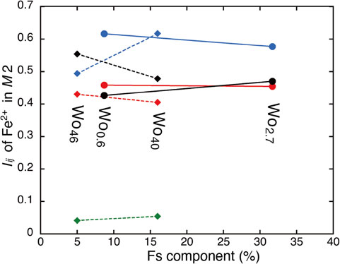
Figure 3 shows the Fs component dependence of the intensity tensor components (IXX, IYY, and IZZ) of the Mössbauer doublet due to Fe2+ at M2 sites. The filled circles show the results for enstatites (1) and (2) of this study. The three components of the intensity tensors commonly show a weak dependence on the Fs component as shown by tie lines with somewhat negative slope. This is consistent with the Fs independence observed for the intensity tensor due to Fe2+ at M1 sites in diopside and hedenbergite (Fukuyama et al., 2022). To compare the Fs dependence of the intensity tensor for equivalent Wo enstatites with the Fs dependence of different Wo enstatites, the results of Fe2+ at M2 sites for diopside and augite with different Wo components in Fukuyama et al. (2022) are shown as filled squares in Figure 3. The intensity tensor components due to Fe2+ at M2 sites in diopside and augite with different Wo components show an intense dependence on the Fs component. Broken lines are simple tie lines to indicate the intense dependence. The difference between the circles and squares in Figure 3 corresponds to the difference in the Wo components. The two Wo components in the present study (circles) are almost equal (Wo0.6 and Wo2.7), whereas the Wo components presented in Fukuyama et al. (2022) are different (Wo40 and Wo46). This indicates that the intensity tensor components due to Fe2+ at M2 sites of enstatite do not significantly depend on the Fs content in enstatite, as well as those of Fe2+ at M1 sites of diopside-hedenbergite clinopyroxenes with equal quantity of Wo component. This suggests that an intensity tensor of a pyroxene with a certain chemical composition, that is not directly determined, can be estimated from the intensity tensor of pyroxenes with the equal Wo and different Fs components. Therefore, this result is important for reliable analyses of Mössbauer spectra of pyroxene single crystal in thin sections which include Fe ions at M1 and M2 sites, because, in the Mössbauer spectroscopic analysis using crystallographically oriented thin sections, the fixing of the peak intensity ratio of a doublet contributes greatly to successfully resolving the overlapped component peaks in the doublet.
CONCLUSION
The Fs dependence of intensity tensors of Mössbauer doublets and EFG tensors by Fe2+ at M2 sites of two enstatites with different chemical compositions were experimentally determined from Mössbauer spectra of crystallographically oriented thin sections. Two orthopyroxenes showed weak Fs dependence of the intensity tensor components for Fe2+ at M2 sites, which is consistent with the weak Fs dependence for Fe2+ at M1 sites in diopside-hedenbergite series of equal Wo.
The intensity tensors under numerical constraints obtained from symmetry considerations are in agreement with the intensity tensors without any numerical constraints. This suggests that the EFG tensor can be simplified by summation of the EFG components of equivalent Mössbauer nuclei, even if a Mössbauer nucleus occupies a general position in the unit cell.
ACKNOWLEDGMENTS
We thank two anonymous reviewers for critical and valuable comments that improve the manuscript. This research was conducted at the Institute for Integrated Radiation and Nuclear Science, Kyoto University, within the Visiting Researcher Program.
REFERENCES
- Bancroft, G.M., Burns, R.G. and Stone, A.J. (1968) Applications of the Mössbauer effect to silicate mineralogy-II. Iron silicates of unknown and complex crystal structure. Geochimica et Cosmochimica Acta, 32, 547-559.
- Cameron, M. and Papike, J.J. (1980) Crystal chemistry of silicate pyroxenes. In Pyroxenes (Prewitt, C.T. Ed.). pp. 525, Reviews in Mineralogy and Geochemistry, 7, Mineralogical Society of America, Washington D.C., 5-92.
- Deer, W.A., Howie, R.A. and Zussman, J. (1978) Rock forming minerals. 2A, Single chain silicates. pp. 3, Longman, London.
- Dowty, E. and Lindsley, D.H. (1973) Mössbauer spectra of synthetic hedenbergite-ferrosilite pyroxenes. American Mineralogist, 58, 850-868.
- Dufek, P., Blaha, P. and Schwarz, K. (1995) Determination of the Nuclear Quadrupole Moment of 57Fe. Physical Review Letters, 75, 3545-3548.
- Fukuyama, D., Shinoda, K., Takagi, D. and Kobayashi, Y. (2022) Compositional dependence of intensity and electric field gradient tensors for Fe2+ at the M1 site in Ca-rich pyroxene by single crystal Mössbauer spectroscopy. Journal of Mineralogical and Petrological Sciences, 117, 011.
- MossWinn - Mossbauer spectrum analysis and database software. http://www.mosswinn.com/ (accessed 2018/7/30).
- Shinoda, K. and Kobayashi, Y. (2019) Determination of the electric field gradient tensor of Fe3+ in the M1 site of aegirine by single crystal Mössbauer spectroscopy. Journal of Mineralogical and Petrological Sciences, 114, 130-141.
- Sueno, S., Cameron, M. and Prewitt, C.T. (1976) Orthoferrosilite: high-temperature crystal chemistry. American Mineralogist, 61, 38-53.
- Tennant, W.C., McCammon, C.A. and Miletich, R. (2000) Electric field gradient and mean-squared-displacement tensors in hedenbergite from single-crystal Mössbauer millprobe measurements. Physics and Chemistry of Minerals, 27, 156-163.
- Travis, J.C. (1971) The electric gradient tensor. In An introduction to Mössbauer spectroscopy (May, L. Ed.). Plenum Press, New York, 75-103.
- Virgo, D. and Hafner, S.S. (1969) Fe2+, Mg order-disorder in heated orthopyroxenes. Mineralogical Society of America Special Papers, 2, 67-81.
- Zimmermann, R. (1975) A method for evaluation of single crystal 57Fe Mössbauer spectra (FeCl2·4H2O). Nuclear Instruments and Methods, 128, 537-543.
- Zimmermann, R. (1983) The intensity tensor formulation for dipole transitions (e.g. 57Fe) and its application to the determination of EFG tensor. In Advances in Mössbauer spectroscopy (Thosar, B.V. Ed.). Elsevier Scientific Publishing Co., Amsterdam, 273-315.
