Layered Microstructure Distribution and Forming Mechanism of Laser-Processed Ni-Fe-B-Si-Nb-C Amorphous Composite Coatings
2016 年 57 巻 10 号 p. 1807-1810

詳細
2016 年 57 巻 10 号 p. 1807-1810
A Ni-based amorphous composite coating was fabricated via laser processing. Its microstructure was observed using scanning electron microscopy (SEM) and transmission electron microscopy (TEM). Cooling behavior during the laser remelting process was simulated using a finite element method. The results indicated that four layers with different microstructures were formed. The layers consist of coarse dendrites, fine dendrites, equiaxed dendrites, and a layer of NbC particles/amorphous phase. Heterogeneous nucleation from NbC particles was observed at the clad/remelt interface. An amorphous phase was the primary phase in the laser remelted layer. Numerical simulation results showed that the cooling rates decreased along the depth direction from the top coating surface. The cooling rate was on the order of 104 K/s. When the cooling rate was higher than the critical cooling rate threshold, an amorphous phase was formed in the remelted layer after the laser remelting process.
In recent years, a lot of research has focused on overcoming the size limitation imposed by the high cooling rates needed in the production of bulk metallic glasses (BMGs). Bulk, glassy, multicomponent alloys with various compositions have been synthesized as rods with diameters up to a few centimeters.1,2) In the case of BMGs based on late transition metals, several families of alloys have been successfully developed.3) Among them, the (Fe,Ni,Co)-B-Si-Nb system can yield alloys with high glass forming ability (diameters achievable up to 5 mm), high fracture strength (σf: ~4000 MPa) and high corrosion resistance.4–8)
Laser processing has attracted attention in the synthesis of metallic glasses, because it can attain very rapid, non-equilibrium cooling, which is very conducive to the formation of a glassy phase. Laser processing techniques such as laser cladding and laser remelting have been utilized in producing various amorphous coatings.9,10) In the last several years, studies have focused on the use of compositions based on (Fe, Ni, Co)-B-Si-Nb alloy systems. These compositions are mostly suitable for surface coatings on traditional steel substrates.
Zhang et al. synthesized Fe-Ni-B-Si-Nb amorphous and nanocrystalline composite coatings by a two-step process - CO2 laser cladding followed by laser remelting. The influence of Si content on the amount of the amorphous phase was studied.11) Li et al. also used a two-step process, consisting of laser cladding followed by laser remelting, to produce Ni-Fe-B-Si-Nb amorphous composite coatings. Laser remelted coatings showed better corrosion resistance than the 316 L stainless steel substrate, as well as laser clad coatings, not subjected to laser remelting.12) Mojaver et al. tried to obtain a completely glassy microstructure using as-cast Fe49Cr18Mo7B16C4Nb3 alloy with pulsed Nd:YAG laser for surface melting.13) This technique could not yield a completely glassy microstructure, and resulted in a mix of amorphous (low volume fraction) and ultrafine-grained phases. Zhu et al. fabricated Fe-Co-B-Si-Nb amorphous coatings by using a one-step single-track laser cladding method. Three layers of different microstructures were formed in the coating.14) Gargarella et al. obtained Fe43.2Co28.8B19.2Nb4Si4.8 glassy matrix composite coatings by employing a laser cladding process, using a pre-placed powder method, on AISI 1020 steel.15) The coating had high hardness exceeding 1040 ± 16 HV0.5, which is more than six times higher than that of the substrate.
In the present work, a Ni-Fe-Si-B-Nb-C amorphous composite coating was fabricated by laser cladding, followed by laser remelting. The microstructure and phase distribution of the amorphous composite coating was studied, and numerical simulations were carried out to determine the mechanisms for microstructure evolution.
An alloy with the composition (Ni0.6Fe0.4)65B18Si10Nb4C3 was selected as the coating material. The particle size of the alloy powder varied in the range of 0.03 mm to 0.05 mm. The powder was fed through a COAX-8 continuous coaxial nozzle using argon as carrier gas flowing at a rate of 12 l/min. Substrates of dimensions of 8 mm × 20 mm × 120 mm were cut from an annealed mild steel sheet, and polished before the laser surface treatment.
Laser processing was done using a 3.5 kW CW high power diode laser (HPDL, model DL035Q). The laser beam was focused to a rectangular spot of approximately 3.3 mm × 2 mm at a distance of 13 mm beyond the nozzle, with a Top-Hat energy distribution. The laser processing was done in two stages - laser cladding, followed by laser remelting. Laser cladding was performed using a beam power of 0.8 kW, scanning speed of 360 mm/min, and a powder feed rate of 12 g/min. Laser remelting was carried out using a beam power of 3.5 kW, and a scanning speed of 8000 mm/min. All the laser processing steps were carried out under an inert argon atmosphere.
Each laser processed coating was transversely cross-sectioned and chemically etched using aqua regia. The microstructures of these coatings were examined using a JSM 6460 scanning electron microscope (SEM) and a PHILIPS CM200 transmission electron microscope (TEM).
Figure 1 shows the cross-sectional macro image and microstructure at different locations on the coating produced by the laser cladding plus laser remelting process described earlier. Figure 1(a) shows the cross-sectional macro image of the coating and the location of the spots A, B, C, and D, where the microstructures shown in Figs. 1(b) thru 1(d) were imaged. Figure 1(b) shows the microstructure at the clad/substrate interface (Spot A). Good metallurgical bonding between the clad and substrate can be seen. A featureless region formed by plane front solidification appears near the interface with the substrate in the bottom region of the coating. The featureless layer is followed by a narrow transition zone with a cellular microstructure, then a thicker region with a columnar dendritic structure. Columnar dendrites with different growth directions at spot B can be observed in Fig. 1(c). Figure 1(d) shows that the microstructure of clad/remelt interface was separated into two layers as indicated by the dotted line - transitional layer I, composed of fine column dendrites, and transitional layer II, composed of equiaxed dendrites. The microstructure at spot D, depicted in Fig. 1(e), shows NbC particles in a featureless amorphous phase. The confirmation of the nature of the featureless phase and NbC particles using XRD and TEM imaging are presented in previous publications.12,16)

Microstructures at different locations on the coating produced by the laser cladding plus laser remelting process. (a) Macro image; (b) Spot A; (c) Spot B; (d) Spot C; (e) Spot D.
Figure 2 shows the magnified views of the two layers shown in Fig. 1(c). Figure 2(a) shows that the columnar dendrites in transitional layer I were finer than those in the portion of the clad layer which did not get remelted. Figure 2(b) shows that some equiaxed dendrites were formed in transitional layer II. Most equiaxed dendrites grow from the NbC particles, as indicated by the white dotted line circle. Figure 2(c) shows a TEM image of the center of an equiaxed dendrite, where an NbC particle can be seen. A schematic illustration of the distribution of microstructure in this laser-processed coating, based on the microstructures shown in Figs. 1 and 2, is depicted in Fig. 3. In the clad region not subjected to remelting, the microstructure consists mainly of coarse columnar dendrites. At the clad/remelt interface, two transitional layers of a fine column dendrite layer and an equiaxed dendrite layer are found. In the laser remelted layer, the primary phases are NbC particles and an amorphous phase.

Local amplification SEM photos and TEM analysis of transitional layer I and II in Fig. 1(d). (a) Clad/Transitional layer I; (b) Transitional layer II/Remelt; (c) TEM of dendrites in Transitional layer II.

Schematic illustration of microstructure distribution in the cross-section of laser cladding plus remelted coating.
In our previous study, we described a finite element method for a direct three-dimensional (3D) temperature field computer simulation of the laser remelting process.17) Figure 4 depicts the finite element model of the clad plus substrate specimen. A non-uniform mesh, which was finer inside the clad region and close to it, was used for this simulation. The simulated thermal cycle (Temperature-Time) results at different depths from the top surface, during the laser remelting process are shown in Fig. 5. It can be seen that the maximum temperature at a depth of 250 μm can reach the liquidus temperature of the Ni-Fe-B-Si-Nb-C alloy (1308 K). Hence, the laser remelting process can lead to the melting of the laser clad coating down to depths of about 250 μm. This result is almost consistent with the remelted depth of the coating, as shown in Fig. 1(a).

Mesh of the FEM model.

Temperature profile at different depths of the laser remelted coating during laser remelting process.
The cooling rates from the highest temperature to Tg (glass transition temperature, 748 K) were calculated, and the results are shown in Fig. 6. It shows that the cooling rates decrease with an increase in the depth from the top surface. These cooling rates are on the order of 104 K/s, which is higher than the critical cooling rate needed for amorphization of an alloy similar to the one under consideration, [(Ni0.6Fe0.4)0.75B0.2Si0.05]96Nb4, estimated to be 49.3 K/s.18)
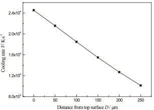
Cooling rates at different depths of the laser remelted coating during laser remelting process.
The melt pool velocity during the laser remelting process can be calculated by eq. (1):19,20)
| \[V = \frac{\sqrt{2c_s} P}{A\rho\lambda}\] | (1) |

Fragmented dendrites near clad/remelt interface(a) and its grain growth behaviour(b).
Based on the microstructure morphology (Fig. 1) and the results of temperature calculation (Fig. 6), we developed mechanisms for the formation of microstructures at different depths, as depicted in Fig. 8. The temperature gradient (G) and the growth rate (R) present during the solidification process determine the microstructure developed on solidification. The G/R ratio determines the solidification mode and the product, G × R, governs the size of the structures developed during solidification, such as crystallites or dendrites. The product G × R is, in fact, the cooling rate (V). The solidification mode changes from planar to cellular and dendritic as the ratio of G/R decreases. The dendrite arm spacing or cell spacing decreases with increasing the product of G × R.23)

Effects of temperature gradient (G) and growth rate (R) on the microstructure morphology, size and amorphous phase formation during solidification process.
In Fig. 8, the cooling curve 1 indicates a low cooling rate. It corresponds to the cooling behavior in the clad. A combination of high temperature gradient (G) and low solidification rate (R) could be obtained here at clad/substrate interface. Here, a large value of G/R will result in a planar solidification structure. At the middle of the laser clad layer, the solidification rate (R) is higher, while the temperature gradient (G) is lower. This suggests that the solidification mode might change to columnar dendritic. The cooling curve 2 corresponds to the cooling behavior at clad/remelt interface. Due to the existence of heterogeneous nucleation, the grain growth rate will increase. In addition, the temperature gradient (G) at clad/remelt interface is also very high, and the product G × R is very large, leading to the very fine dendrites and equiaxed dendrites here.
Simulation results indicate that the cooling rate is much higher in the laser remelted layer, which corresponds to cooling curve 3, than the cooling rates corresponding to cooling curves 1 and 2. There is a high possibility that this cooling rate is higher than the critical cooling rate (the dotted cooling curve shown in Fig. 8) for the amorphous phase formation, and hence, the amorphous phase was formed in the remelted layer after the laser remelting process.
A Ni-based amorphous composite coating was fabricated by laser cladding followed by laser remelting. Four layers with different microstructures were observed in the coating. The four layers are a coarse dendrite layer, a fine dendrite layer, an equiaxed dendrite layer, and a NbC particles/amorphous phase layer. Thermal simulation of the process indicates that cooling rates on the order of 104 K/s can be achieved in the coating. However, the cooling rates decrease with increase in depth. The observed microstructures and calculated cooling rates indicate that attaining very high cooling rates is a key factor for amorphous formation in the laser remelted layer.
The authors acknowledge the financial support provided by the National Natural Science Foundation of China (Grant No. 51405206), the Natural Science Foundation of Jiangsu Province (Grant No. BK20130469), Qing Lan Project and the Open Project Foundation in Shanghai Key Laboratory of Laser Processing and Modification (No. MLPM2016-1).