Sterilization by a Pulsed Electric Field with Dendritic Gold Electrodes
2018 Volume 59 Issue 7 Pages 1210-1213

Details
2018 Volume 59 Issue 7 Pages 1210-1213
The dendritic gold electrodes effectively inactivated Escherichia coli (E. coli) by pulsed electric field (PEF) sterilization. Two phenomena are involved: (1) The dendritic structures induce a dielectrophoretic (DEP) force which drives E. coli toward the vicinity of the dendrites. (2) High-intensity electric fields around the dendrite tips distort the cell walls of E. coli as a result of potential disturbance, which subsequently kill the E. coli. The inactivation rate of E. coli on the dendritic electrodes depended on the pulse frequency more strongly than on an as-sputtered smooth electrode, suggesting that the DEP force is operative during PEF sterilization.
Treatment by heating and chemical agents are two common methods for sterilizing food and medical products. However, both these treatments risk degrading the components and/or flavors of the sterilized products. These methods are also ineffective for killing bacteria with strong resistance to heat and chemical agents. Hence, it is worthwhile to develop new sterilization systems that are effective in these areas where conventional treatments are not.1–3)
One potential solution is to use a pulsed electric field (PEF).4) Previous studies have shown that when a bacterium is placed in the vicinity of a high intensity PEF, the bacterium immediately dies due to irreparable pores induced in its cell membrane by the PEF. The practical use of PEF sterilization has yet to be realized, because it requires a high voltage to satisfactorily induce nanopores in the cell membrane.5)
Metallic dendrites are promising electrode structures6) for lowering the voltage required for effective PEF sterilization. The dendrites with sharp tips distort the spatial distribution of the ambient electric field. This distortion of the electric field gives rise to two significant phenomena for a cell and its membrane. The first phenomenon is dielectric polarization in the cell which is induced by the external electric field, which is known as dielectrophoresis (DEP).7,8) In the distorted electric field, DEP attracts cells to the surface of an electrode. The attractive force (DEP force, FDEP) on a spherical cell is represented by the following expression:
| \begin{equation} \boldsymbol{{F}}_{\text{DEP}} = 2\pi a^{3}\varepsilon_{\text{m}}\text{Re}[f_{\text{CM}}(\tilde{\varepsilon}_{\text{p}},\tilde{\varepsilon}_{\text{m}})]\boldsymbol{{\nabla}} | E |^{2} \end{equation} | (1) |
| \begin{equation} \Delta V = 1.5aE\cos \theta, \end{equation} | (2) |
The purpose of the current study is to elucidate how the dendritic structures on the electrode facilitate the inactivation of bacteria (E. coli). The participation of the two above-mentioned phenomena is discussed.
We prepared gold comb electrodes for PEF sterilization (Fig. 1) on 18 mm × 18 mm glass sheets, by radio-frequency magnetron sputtering (SVC-700RF, Sanyu Electron Co., Ltd., Tokyo, Japan) using a metal mask. The distance between the two electrodes (i.e. the gap between them) was 0.25 mm. We chose gold because of its chemical inertness, to ensure that no antibacterial metallic ions were released from the electrodes.

Schematic diagram for comb electrode used in PEF sterilization.
Dendritic gold was then electrodeposited on the comb electrode surface. An electrolyte containing 20 mmol/L HAuCl4, 0.5 mol/L H2SO4, and 150 mmol/L C4H5N3O (cytosine) was used in the electrochemical deposition. Cytosine is frequently employed in gold dendritic structures.17) Specifically, after gold nuclei are deposited on the electrode surface, cytosine molecules selectively adsorb on specific crystal planes of the gold nuclei. This prevents the gold atoms from further aggregating, and consequently facilitates crystal growth in a particular crystallographic direction.17) We used the comb electrode as a cathode, and platinum as the anode. We then applied a direct current to the electrodes for 2 min with a potential difference of 1 V, and then thoroughly washed the comb electrode with pure water.
For comparison, two other types of gold comb electrode were also fabricated. One was fabricated without the deposition of gold dendrites, so had an “as-sputtered” surface. The other was fabricating with the electrodeposition of gold but without cytosine. As demonstrated later, the absence of cytosine led to the deposition of leaf-like plates and not dendrites.
The microstructures of the three types of electrodes were observed using a scanning electron microscope (SEM) (S-4300, Hitachi High-Technology, Japan) with an attached energy-dispersive X-ray spectrometer (EDXS) (XFlash 5010, Bruker AXS, Germany).
We prepared the microbial suspension containing a platinum loop of Escherichia coli (E. coli, K-12, NBRC 3301) and 4.5 mL of phosphate buffer solution (PBS). The initial concentration of viable bacteria in the suspension was approximately 1.0 × 10⁵ colony forming units per milliliter (CFU/mL).
In PEF sterilization, we dropped 5 µL of the bacterial suspension on top of the comb electrode, and then applied a square-wave potential pulse using a function generator (AWG-2225 JW INTEK, New Taipei City, Taiwan). The conditions of the pulse were set to a maximum of 5 V, a duty ratio of 50%, and a frequency of 1 kHz. The number of cycles was 100 in most runs. Higher frequencies of 24 MHz and 300 MHz were also tested for comparison.
After applying the pulse, we washed out the suspension with 5 mL of soybean-casein digest broth with lecithin and polysorbate, and then poured 0.5 mL of the washing-out solution into a test tube containing 4.5 mL of PBS. After mixing the washing-out solution and PBS, 0.5 mL of the resulting solution was transferred to another test tube containing 4.5 mL of PBS, which was again thoroughly mixed. This operation was repeated until a 10-fold dilution series was prepared. 1 mL of each dilution was transferred into a sterilized plastic dish. 20 mL of agar medium that had been kept at 50°C was added to each dish, followed by thorough mixing. To calculate the control viable bacterial concentration, we also prepared solutions without applying the pulse (PBS 4.5 mL + bacterial suspension 5 µL), and then went through the same procedure as above. After the agar medium solidified, the dishes were inverted and cultured for 48 h in an incubator at 35°C. After this, the number of colonies in each dish was counted. We calculated the viable bacterial concentration (CFU/mL) using the following formula:
| \begin{align} \text{CFU$\,$mL$^{-1}$} &= \text{Number of colonies} \\ &\quad\times \frac{1}{\text{dilution factor}} \times \frac{1000\,\text{$\mu$L$\,$mL$^{-1}$}}{5\,\text{$\mu$L}}, \end{align} | (3) |
| \begin{align} &\text{Bacterial inactivation rate} \\ &\quad= \left(1 - \frac{\text{CFU$\,$ml$^{-1}$ for condition}}{\text{CFU$\,$ml$^{-1}$ for control}} \right) \times 100\%. \end{align} | (4) |
SEM images of the gold electrodes are shown in Figs. 2(a)–(c). The as-sputtered gold electrode (without subsequent electrodeposition of gold) had a smooth and featureless surface (Fig. 2(a)). Gold dendrites were fabricated by electrodeposition in a bath containing cytosine. Figure 2(b) shows an SEM image of the dendrites on the sputtered gold electrodes. The dendrite cell size and dendrite arm spacing were 63 ± 18 nm and 55 ± 9 nm, respectively, which were measured using images observed with magnification higher than adopted in Fig. 2(b). The typical length of the main dendrite branch was 5 µm, while that of the secondary branch was 1 µm, both of which were similar to the size of a single E. coli cell. Figure 2(c) shows an SEM image of the electrode surface fabricated without cytosine. Leaf-like plates with a thickness of 50 nm and average side length of 0.7 µm were uniformly dispersed on the electrode surface. Comparison of the SEM images reveals that cytosine in the electrodeposition bath led to the gold dendritic structure, by adsorbing to the gold nuclei and facilitating anisotropic growth to form the regular dendritic shape in Fig. 2(b).
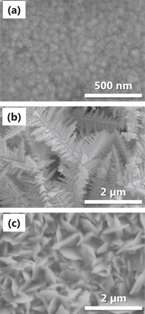
SEM images of (a) as-sputtered, (b) dendritic and (c) leaflike gold electrodes.
Figure 3 shows EDXS spectra of the fabricated gold electrodes. The spectral peaks of each electrode were consistent with the peaks of Au, and no peaks other than a small peak of Si from underlying glass substrate were detected. This demonstrates that the microscopic structure deposited on the electrode surface contained metallic gold as the main component.

EDXS results for dendritic and leaflike gold electrodes.
Figure 4(a) shows the E. coli inactivation rates for the three types of gold-fabricated electrodes in PEF sterilization at 1 kHz. The electrodes with dendritic and leaf-like structures killed E. coli more efficiently than the as-sputtered electrode. The cell inactivation rate of the dendritic gold electrode was higher than that of the electrode with leaf-like structures. Thus, the size and geometry of the microscopic structure is important in the inactivation of E. coli.

(a) Inactivation rates of E. coli in PEF sterilization with gold electrodes at frequency of 1 kHz. (b) Dependence of inactivation rates of E. coli in PEF sterilization with as-sputtered and dendritic gold electrodes on frequency of PEF. Error bars show standard deviation.
Figure 4(b) shows the cell inactivation rates for the as-sputtered and dendritic gold electrodes in PEF sterilization at high frequencies (24 MHz or 300 MHz). The cell inactivation rates of the dendritic electrode were always higher than those of the as-sputtered electrode, irrespective of the frequency (including at low frequency of 1 kHz). The cell inactivation rates at 24 MHz were lower than those at 1 kHz. However, the inactivation rate of the as-sputtered electrode decreased by a factor of 0.65 compared with the inactivation rate at 1 kHz, whereas the inactivation rate of the dendritic electrode decreased by a factor of 0.44. Hence, the decrease in the cell inactivation rate for the dendritic electrode at the increased frequency was larger than that for the as-sputtered gold electrode. In other words, the cell inactivation rate for the dendritic electrode was more dependent on the frequency used for PEF sterilization than that of the as-sputtered electrode.
Figure 4(a) indicates that the inactivation rate for the as-sputtered gold electrode was lower than those for the microstructured gold electrodes. This implied that the surface microstructures on the electrodes promoted the inactivation of E. coli. When the electrode surface microstructure had a typical length comparable to the size of an E. coli cell, the distribution of the electric field near the electrode was distorted, and the volume occupied by the high intensity electric field increased. Thus, E. coli near the surfaces of the microstructured electrodes were more frequently exposed to the strong electric field, than E. coli near the surface of the as-sputtered electrode with a uniform electric field. This led to the higher inactivation rates for the microstructured electrodes. Hence, a denser microstructure led to a higher inactivation rate in the PEF. Although weak electric field regions were also generated simultaneously, E. coli cells were repelled from weak electric field regions by the DEP force, and subsequently were attracted to strong electric field regions. This is discussed in more detail later.
As shown in Fig. 4(a), E. coli was inactivated more efficiently when using the dendritic electrode than when using the leaf-like electrode. This was because the typical length (5 µm) of main branch of the dendritic electrode was larger than the average side length (0.7 µm) of the deposited plates in the leaf-like electrode. The dendritic structure was the most effective for increasing the inactivation rate among the tested gold electrodes. The size of the strong electric field on the dendritic surface inevitably became large, and consequently a large number of E. coli were inactivated.
The results of PEF sterilization under various frequencies (Fig. 4(b)) suggest that DEP contributed to cell inactivation. The inactivation rates for the as-sputtered and dendritic electrodes decreased when the frequency was increased from 1 kHz to 24 MHz and then to 300 MHz. The total pulse application time (pulse width × number of cycles) was one reason for the decrease in inactivation rate, because the number of cycles was constant (100 cycles) in each PEF sterilization procedure.18) However, the cell inactivation rate of the dendritic electrode decreased more significantly than that of the as-sputtered electrode, when higher frequencies were used. The inactivation rate for the dendritic electrode strongly depended on the pulse frequency.
The difference in frequency dependence of inactivation rate between the dendritic and as-sputtered electrodes can be explained by the difference in microscopic surface structure of the electrodes. The surface of the as-sputtered electrode was smooth with little roughness, thus the electric field distribution was spatially uniform. The DEP force does not act on bacteria such as E. coli in such a uniform electric field. However, the electric field distribution was distorted by microscopic protrusions on the surface of the dendritic gold electrode, so the electric field distribution became nonuniform. Therefore, the DEP force was operative, pushing E. coli out of the weak electric field region towards strong electric field regions. Furthermore, since the CM factor in the expression of DEP force (eq. (1)) depends on frequency (in the case of E. coli, as frequency increases, the CM factor generally decays19,20)), when the pulse frequency increased, the DEP force decreased. Therefore, the capacity of drawing E. coli towards strong electric field regions near the tips of the dendrite structure weakened. This accounted for the lower inactivation rates at 24 MHz and 300 kHz, compared with at 1 kHz. Conversely, the DEP force acted on E. coli on the as-sputtered electrode less efficiently than on the dendritic electrode. Therefore, the decrease in inactivation rate for the as-sputtered electrode was less evident than that for the dendritic electrode.
Dendritic and leaf-like gold structures were prepared by electroplating, and their effects on the PEF sterilization of E. coli were examined. We hypothetically considered the following two phenomena regarding the electric field distribution near the dendritic microstructures.
We examined how the cell inactivation rates of E. coli were affected by the microstructures on the electrode surface, and we evaluated the frequency characteristics of the inactivation rates, in light of the above-mentioned considerations. The inactivation of E. coli was most pronounced on the dendritic gold electrode, which also showed prominent dependence on the PEF frequency. These experimental results support our initial hypotheses: that the DEP and concentration of electric field are responsible for the enhanced pulse electric field sterilization of E. coli by dendritic gold electrodes.
The authors acknowledge financial support by JSPS KAKENHI (Grant No. JP15H05547).