Anisotropic Mechanical Properties of Columnar and Equiaxed A6005C Aluminum Alloys Fabricated by Capillary Shaping
2019 年 60 巻 1 号 p. 10-18

詳細
2019 年 60 巻 1 号 p. 10-18
Capillary shaping is an attractive directional solidification process of fabricating lightweight aluminum frame components for automobiles. In this study, the strengths of capillary shaped A6005C aluminum alloys were investigated under various conditions. Tensile tests were performed parallel to and perpendicular to the pulling direction, to investigate columnar and equiaxed grain structures, as-cast and T6 heat-treated conditions, and different crystal orientations. In columnar grain specimens, the strength parallel to the pulling direction was higher than that perpendicular to the pulling direction in both as-cast and T6-treated conditions. Crystal orientation affected the work hardening behavior of as-cast specimens loaded perpendicular to the pulling direction. In equiaxed grain specimens, the anisotropy and the distribution of mechanical properties were quite low in both as-cast and T6-treated conditions.
Capillary shaping is a directional solidification technique that can be used to fabricate lightweight aluminum frame components of automobiles.1–10) In this technique, a component with a controlled cross-section is drawn upward from an aluminum alloy melt while cooling the position above the solid-liquid interface. This enables frames with complex geometries to be easily obtained using a small apparatus. Directional solidification permits the formation of high strength aluminum alloys, e.g. A6000 and A7000 series alloys, despite their high solidification cracking sensitivity.8) Superior geometrical freedom offers high structural stiffness, a highly desirable characteristic for aluminum frames.
In the directional solidification processes, columnar grain structures often form along the heat flux direction, resulting in different mechanical properties for longitudinal and transverse sections.11–13) In capillary shaping, a columnar structure also forms longitudinally, but tends to tilt from the pulling direction due to variation in solid-liquid interface height.9,10) Unfortunately, the mechanical properties of capillary shaped commercial aluminum alloys have not yet been investigated in detail. Furthermore, there is a lack of understanding of influence of crystallographic orientation on the mechanical properties, although the preferred ⟨100⟩ growth axis of the aluminum phase aligns directionally.7)
In this study, we investigated the mechanical properties of A6005C aluminum alloys fabricated by the capillary shaping technique, considering columnar and equiaxed structures, anisotropy between the longitudinal and transverse sections, as-cast and T6 heat treated conditions, and crystal orientations.
Square aluminum alloy pipes 63.1 ± 0.2 mm wide and 800 mm long with a 6.3 ± 0.3 mm wall thickness were fabricated by capillary shaping, as shown in Fig. 1. A6005C (JIS-6N01) aluminum alloy, with the composition shown in Table 1, was kept at 973 ± 3 K in an alumina crucible. A6005C alloy forms a columnar grain structure. Al–Ti–B master alloy was added to the A6005C-Ti alloy melt as a grain refiner to obtain an equiaxed grain structure. An Ar bubbling treatment was conducted to reduce the dissolved hydrogen in the melt. Then, the oxide film on the melt surface was removed and a part of the melt was quenched to analyze the chemical composition and hydrogen content of the melt. A shaping device having a square opening with an outer width of 64 mm and an inner width of 50 mm (defining a 7 mm wide channel) was placed on the melt surface. The shaping device was made of a 2-mm-thick 304 stainless steel plate powder-coated with BN. A square extrusion pipe composed of A6063 aluminum alloy was used as a starting device. Cooling nozzles were placed 6 mm above the shaping device. The pulling process was started by dipping the starting device into the melt through the opening of the shaping device, waiting for 10 s, and withdrawing the starting device with coolant air directed toward each exterior wall of the starting device. The flow rate of the coolant air was 120 L/min for each wall. The pulling rate was 0.5 mm/s. A laser positioning meter was used to measure the melt level in order to control the pulling rate and positioning of the shaping device.
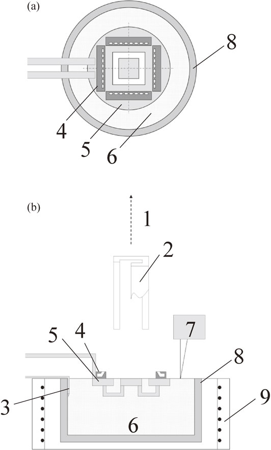
Schematics of the capillary shaping apparatus for the formation of square pipes. 1) Pulling path, 2) starting device, 3) thermocouples, 4) cooling nozzles, 5) shaping device, 6) melt, 7) laser position meter, 8) alumina crucible, 9) electric resistance heater. (a) Upper view of the shaping device, cooling nozzles, and melt. (b) Cross-sectional view.
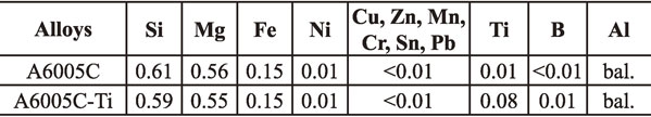
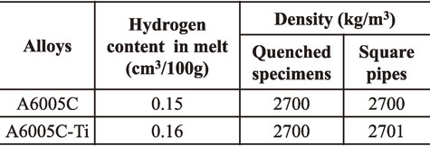
Table 2 lists the hydrogen contents of the melts measured by Ransley’s method,14) and the densities of quenched specimens and capillary shaped square pipes determined by the Archimedes’ method. The hydrogen contents were low enough to prevent gas porosity formation during the capillary shaping process. Indeed, the density of the square pipes matched that of the quenched specimens.
As-cast square pipes were cut into 100-mm-long segments. Figure 2(a) shows the appearance of one such A6005C alloy segment. Square pipes with accurate wall thickness were obtained. The macrostructures of the front surface (S1) and right surface (S2) of a typical A6005C alloy pipe are shown in Figs. 2(b) and 2(c), demonstrating that columnar grains formed on both surfaces. The crystallographic orientations of the columnar grains (G1–G7) were determined from the ⟨001⟩ dendrite growth directions. For this purpose, stereographic projections were used to analyze the crystallographic orientation of the [001] direction of the primary dendrite trunks observed perpendicular to the A1 and A2 axes and the [100] and [010] directions of the secondary dendrite branches observed on a plane perpendicular to the A3 axis, where the A1 axis was the wall thickness direction, the A2 axis was the width direction, and the A3 axis was antiparallel to the pulling direction. The inclination angle between the primary dendrite and the A3 axis Ψ1 of grains (G1–G7) are shown in Figs. 2(b) and 2(c). The growth direction of the columnar gains in the S1 surface was nearly antiparallel to the pulling direction, whereas some of the columnar grains in the S2 surface were inclined by more than 10° toward the front surface, indicating that the height of the solid-liquid interface at the S1 surface was higher than that at the rear surface during the pulling process.7,10)
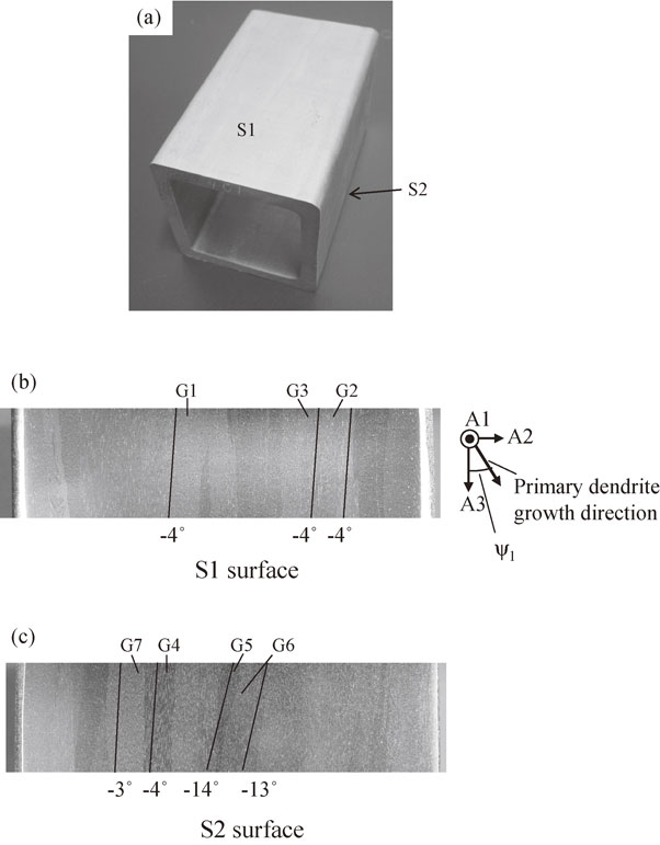
(a) Appearance of a square pipe made of A6005C alloy, and (b, c) macrostructures on the front surface (S1) and right surface (S2). Ψ1 is defined as the inclination angle between the growth direction of the primary dendrite trunk and the A3 axis.
Some of the 100-mm-long segments were heat treated under the T6 condition, i.e., solution treatment at 805 K for 3 hours, water quenching, and artificial aging at 444 K for 8 hours immediately after quenching.
Tensile test specimens that were 5 mm wide, 2 mm thick, and had a 15 mm gauge length were obtained parallel and perpendicular to the pulling direction (hereafter referred to as 0° and 90° specimens, respectively) from the S1 and the S2 surfaces of A6005C and A6005C-Ti alloy segments in as-cast and T6-treated conditions. Tensile tests were carried out with a 0.0167 mm/s crosshead rate. 0.2% proof strength σ0.2 was determined by two strain gauges, and fracture strain εf was determined using an optical projector.
2.4 Microstructure analysisMicrostructures were observed using a polarized microscope after anodization treatment (Barker’s etching). Mg, Si, and Ti distributions in the microstructures of as-cast and T6-treated A6005C and A6005C-Ti alloys were determined by EPMA. The fracture surfaces of the tensile test specimens were observed by SEM.
Figure 3 shows the microstructures of A6005C and A6005C-Ti alloy pipes. The cell size of the columnar dendrite trunk in the A6005C alloy pipe was determined from the intervals of dendrite branches observed in the cross-section, as shown in Fig. 3(b), and was approximately 160 µm. In contrast, the equiaxed grains of the A6005C-Ti alloy pipe were randomly distributed and the grain size was approximately 150 µm (Fig. 3(c), (d)).
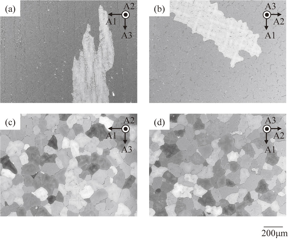
Solidification structures of (a, b) A6005C alloy and (c, d) A6005C-Ti alloy.
Figure 4 shows Si, Mg, and Ti distributions in as-cast and T6-treated A6005C and A6005C-Ti alloys. The secondary electron (SE) images indicate that intermetallic compounds precipitated along the inter-dendrite region or grain boundaries and remained after the T6 treatment. In as-cast specimens, the concentrations of Si and Mg in the center of the columnar dendrites and within the equiaxed grains were lower than those near the inter-dendritic regions and grain boundaries, since the equilibrium distribution coefficients k of Si and Mg were lower than unity (k < 1). Si and Mg were homogeneously distributed after the solution treatment. In contrast, Ti segregated at the center of the equiaxed grains in both as-cast and the T6-treated specimens due to its large equilibrium coefficient (k > 1) and low diffusion coefficient in the aluminum matrix. These distributions imply that the strength of the center of the columnar dendrites were lower than that near the inter-dendritic regions in the as-cast condition.

Si, Mg, and Ti distributions in as-cast and T6-treated A6005C and A6005C-Ti alloys. All concentrations are shown as mass percent.
Table 3 lists the ultimate tensile strength σUTS, the 0.2% proof strength σ0.2, and the fracture strain εf of A6005C and A6005C-Ti alloys. Sections 3.2.1 and 3.2.2 discuss the tensile properties of A6005C alloy specimens, and those of A6005C-Ti alloy specimens are described in section 3.2.3.
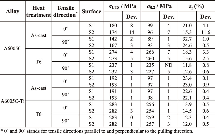
Figure 5 shows the relationship between the fracture strain and the ultimate tensile strength of the A6005C alloy specimens. The ultimate tensile strength of the T6-treated specimens was higher than that of the as-cast specimens. In the as-cast specimens, the ultimate tensile strength decreased with increasing fracture strain. In contrast, the ultimate tensile strength of the T6-treated specimens increased with increasing fracture strain. The strength of the 0° specimens was higher than that of the 90° specimens in both as-cast and T6-treated specimens. It must be noted that the mechanical properties were widely distributed in both as-cast and the T6-treated conditions regardless of the tensile direction.
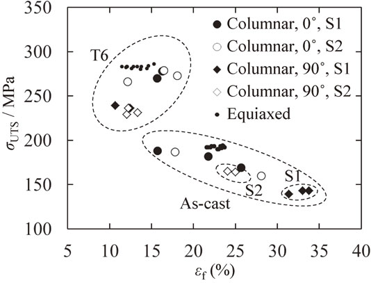
Relationship between fracture strain εf and ultimate tensile strength σUTS in A6005C and A6005C-Ti alloys.
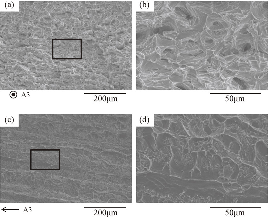
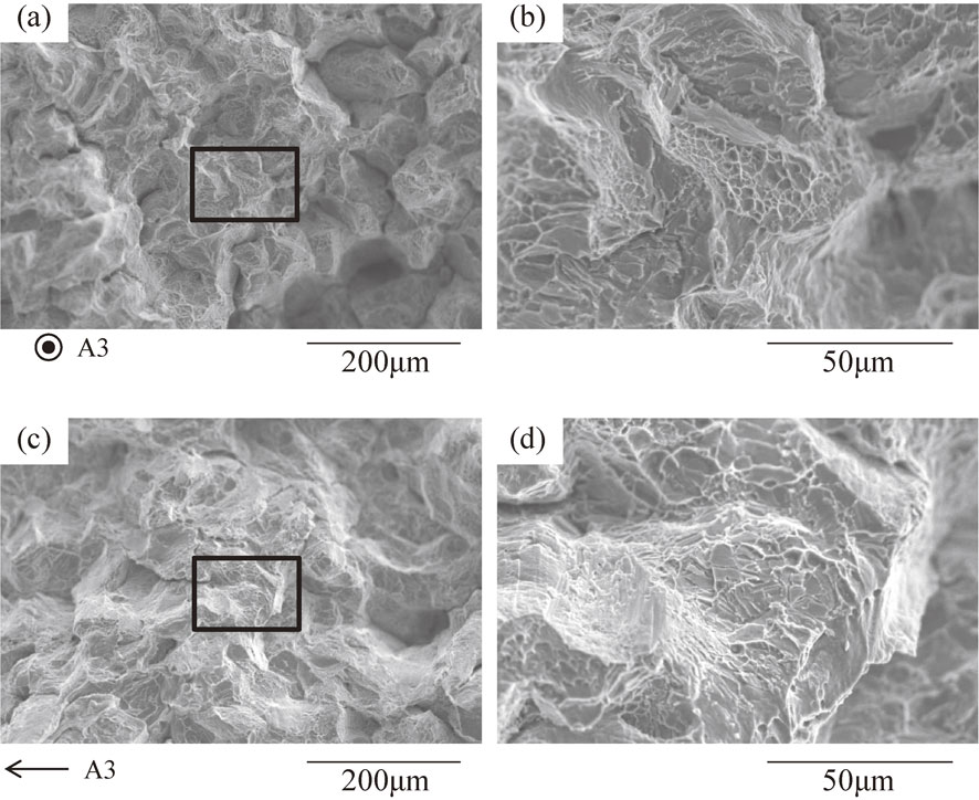
Figure 6 shows the fracture surfaces of several as-cast specimens. In the 0° specimens (Figs. 6(a), (b)), the columnar dendrites separated at the inter-dendrite regions, forming holes. Furthermore, the columnar dendrites were extremely deformed, with fine dimple formation in the centers of the failed dendrites. In contrast, the 90° specimen failed along the inter-dendrite regions (Fig. 6(c)), followed by the formation of fine dimples (Fig. 6(d)).
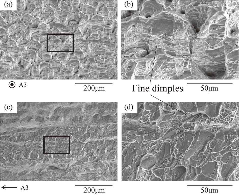
Fracture morphology observed for 0° (a, b) and 90° (c, d) specimens of as-cast A6005C alloy.
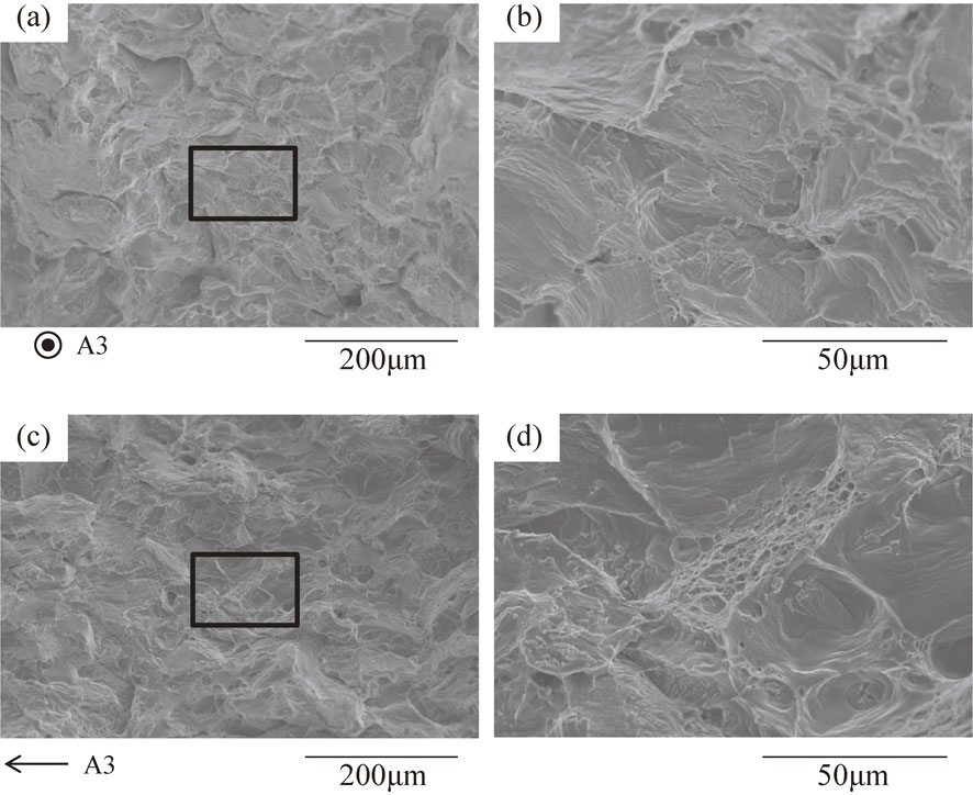
Figure 7 shows the fracture surfaces of several T6-treated specimens. In the 0° specimens (Figs. 7(a), (b)), no separation of the columnar dendrite at the inter-dendrite region was visible and no fine dimples were observed. In the 90° specimens (Figs. 7(c), (d)), fracture occurred along the inter-dendrite regions.
Fracture morphology observed for 0° (a, b) and 90° (c, d) specimens of T6-treated A6005C alloy.
The intergranular fracture in high strength A6000 series alloys has been explained by precipitation hardening of the aluminum matrix and preferred plastic deformation in the precipitation-free zone (PFZ).15,16) Intermetallic compounds precipitated at the grain boundaries during solidification and heat treatment promote intergranular fracture. The T6-treated specimens seemed to fail in this manner, since the columnar dendrites were precipitation hardened but the intermetallic compounds remained in the inter-dendrite regions. In this situation, both the fracture strain and the ultimate tensile strength depended upon failure at the grain boundaries, so the ultimate tensile strength increased as the fracture strain increased. This failure mechanism was not the case for as-cast specimens. The columnar dendrites in the as-cast specimens deformed easily before inter-dendritic failure due to the low concentrations of Si and Mg in the centers of the columnar dendrites. In this case, lowering the strength of the columnar dendrites induces extensive deformation before fracture at the inter-dendrite regions. Therefore, the fracture strain increased with decreasing ultimate tensile strength.
The difference between the ultimate tensile strengths of 0° and 90° specimens in as-cast condition can be explained as follows. The ultimate tensile strength of the 90° specimens depends on the strength inside the columnar dendrites, where the Si and Mg concentrations were the lowest. In contrast, the strength of as-cast 0° specimens depends on the local strength inside the columnar grains and near the inter-dendrite regions.
The wide scattering of ultimate tensile strength and fracture stain values probably resulted from the columnar structure. The dispersal of intermetallic compounds along the inter-dendrite regions and grain boundaries would increase the sensitivity to local fracture, leading to a wider observed distribution of mechanical properties.
3.2.2 Influence of crystal orientation on mechanical propertiesFigure 5 also shows the ultimate tensile strength obtained from the S1 and the S2 surfaces of the A6005C alloy. In only the as-cast 90° specimens, the ultimate tensile strength of the S2 surface was clearly higher than that of the S1 surface. This difference was not a result of the cooling conditions during the pulling process, since the effect was not observed in the 0° specimens. Instead, work hardening was more important in this case, as shown in the stroke-load curves (Fig. 8).
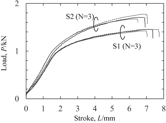
Stroke x and load L curves obtained during tensile tests from 90° specimens of as-cast A6005C alloy.
Figure 9 shows the appearances of these specimens after the tensile tests. As shown in Fig. 9(a), the specimens obtained from the S1 surface necked not only near the region of failure, but also other positions (indicated by triangles). Arrows in Figs. 9(a) and 9(b) indicate deformation patterns that appeared along grain boundaries. These patterns were caused by different deformations and rotations of grains, as shown in the side view (Fig. 9(c)), indicating that deformation of the tensile specimens was dependent upon crystal orientation.
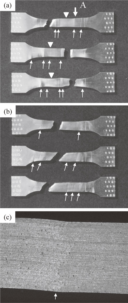
Appearance of 90° specimens of as-cast A6005C alloy obtained from the S1 surface (a) and S2 surface (b). Arrows in (a) and (b) indicate deformation patterns that appeared along grain boundaries. Triangles in (a) indicate necked parts. (c) Shows a side view of location A indicated by the bold arrow in (a).
Figure 10 shows inverse pole figures that relate the tensile direction to the crystal orientations of seven grains (G1–G7) in Fig. 2. As shown in Fig. 10(a), the crystal orientations in the 0° specimens obtained from the S1 surface nearly coincided with ⟨100⟩, since the primary dendrite trunk [001] grew parallel to the A3 axis with small inclination angles of less than 5°. In contrast, the crystal orientations in the 0° specimens obtained from the S2 surface were slightly farther from ⟨100⟩, because the growth direction of the primary dendrite trunk [001] inclined approximately 10° toward the A3 axis. The crystal orientations in the 90° specimens are plotted in Fig. 10(b). Because the columnar dendrites rotated around the primary dendrite trunk, the angle between the secondary dendrite branch [100] direction and the A2 axis varied between 0° and 45°. Thus, the crystal orientations in the 90° specimens obtained from the S1 surface were located between ⟨100⟩ and ⟨110⟩. The crystal orientations in the 90° specimens obtained from the S2 surface spread toward the ⟨100⟩ to ⟨111⟩ line due to superposition of the rotation of the secondary dendrite branches onto the tilt of the primary dendrite trunk.
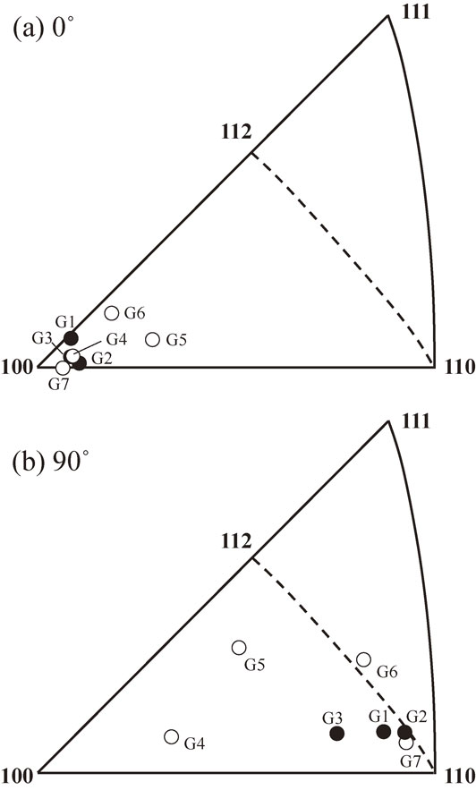
Inverse pole figures for the 0° and 90° specimens in the A6005C alloy.
It has been reported that the strength of pure aluminum single crystals is 22 MPa, 32 MPa, 40 MPa, and 80 MPa for tensile directions parallel to the ⟨100⟩, ⟨112⟩, ⟨110⟩, and ⟨111⟩ directions, respectively.17–19) The highest strength of ⟨111⟩ was explained by work hardening through cross slip and multiple slip. This work hardening was promoted by the compressive cross slip occurring in the crystal orientation region among ⟨110⟩, ⟨112⟩, and ⟨111⟩.17) In pure aluminum bi-crystals, secondary slip was often induced by the misorientation of grain boundaries.17,20) Thus, the work hardening caused by the multiple slip propagates to neighboring grains as if the grain size were quite coarse. In this study, the work hardening of the 90° specimens obtained from the S2 surface was more apparent than that obtained from the S1 surface in the as-cast condition because the former specimens contained a grain close to ⟨111⟩.
It must be noted that the crystal orientation is less important in T6-treated specimens and as-cast 0° specimens, because the local mechanical properties at grain boundaries and in inter-dendrite regions controlled the overall mechanical properties of the specimens.
3.2.3 Equiaxed structure specimensThe mechanical properties of A6005C-Ti alloy specimens are shown in Table 3 and Fig. 5. Due to the Ti addition, σUTS of the A6005C-Ti alloy was higher than that of A6005C alloy in both as-cast and T6-treated conditions. The anisotropy and distribution of σUTS, σ0.2, and εf values of the A6005C-Ti alloy were much smaller than those of the A6005C alloy.
Figures 11 and 12 show the fracture surfaces of as-cast and T6-treated A6005C-Ti alloys. The as-cast and the T6-treated 0° and 90° specimens failed by intergranular fracture with dimple formation, indicating that more isotropic properties and narrower property distributions resulted from the equiaxed structure. The intergranular fracture of the T6-treated specimens occurred due to the preferred plastic deformation of the PFZ and the failure of the intermetallic compounds precipitated at the grain boundaries.15,16) In contrast, the as-cast specimens failed by intergranular fracture with higher fracture strain. In these specimens, the plastic deformation seemed to occur at both the interior of grains and the intergranular regions due to the lower concentration of Si and Mg in the grains and the formation of PFZ induced by the low cooling rate during the pulling process, resulting in the superior fracture strain.
Fracture morphology observed for 0° (a, b) and 90° (c, d) specimens of as-cast A6005C-Ti alloy.
Fracture morphology observed for 0° (a, b) and 90° (c, d) specimens of T6-treated A6005C-Ti alloy.
In this study, we investigated the mechanical properties of capillary shaped A6005C aluminum alloys, considering columnar and equiaxed structures, anisotropy between the longitudinal and transverse sections, as-cast and T6 heat-treated conditions, and crystal orientation. Our findings can be summarized as follows: